2001 DODGE RAM engine coolant
[x] Cancel search: engine coolantPage 1522 of 2889
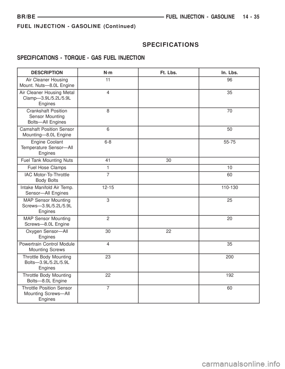
SPECIFICATIONS
SPECIFICATIONS - TORQUE - GAS FUEL INJECTION
DESCRIPTION N´m Ft. Lbs. In. Lbs.
Air Cleaner Housing
Mount. NutsÐ8.0L Engine11 9 6
Air Cleaner Housing Metal
ClampÐ3.9L/5.2L/5.9L
Engines435
Crankshaft Position
Sensor Mounting
BoltsÐAll Engines870
Camshaft Position Sensor
MountingÐ8.0L Engine650
Engine Coolant
Temperature SensorÐAll
Engines6-8 55-75
Fuel Tank Mounting Nuts 41 30
Fuel Hose Clamps 1 10
IAC Motor-To-Throttle
Body Bolts760
Intake Manifold Air Temp.
SensorÐAll Engines12-15 110-130
MAP Sensor Mounting
ScrewsÐ3.9L/5.2L/5.9L
Engines325
MAP Sensor Mounting
ScrewsÐ8.0L Engine220
Oxygen SensorÐAll
Engines30 22
Powertrain Control Module
Mounting Screws435
Throttle Body Mounting
BoltsÐ3.9L/5.2L/5.9L
Engines23 200
Throttle Body Mounting
BoltsÐ8.0L Engine22 192
Throttle Position Sensor
Mounting ScrewsÐAll
Engines760
BR/BEFUEL INJECTION - GASOLINE 14 - 35
FUEL INJECTION - GASOLINE (Continued)
Page 1530 of 2889
(1) Install IAC motor to throttle body.
(2) Install and tighten two mounting bolts (screws)
to 7 N´m (60 in. lbs.) torque.
(3) Install electrical connector.
(4) Install air cleaner assembly.
INSTALLATION - 8.0L
The IAC motor is located on the back of the throt-
tle body (Fig. 33).
(1) Install IAC motor to throttle body.
(2) Install and tighten two mounting bolts (screws)
to 7 N´m (60 in. lbs.) torque.
(3) Install electrical connector.
(4) Install air cleaner housing to throttle body.
(5) Install 4 air cleaner housing mounting nuts.
Tighten nuts to 11 N´m (96 in. lbs.) torque.
(6) Install air cleaner housing cover.
INTAKE AIR TEMPERATURE
SENSOR
DESCRIPTION - 3.9L/5.2L/5.9L/8.0L
The 2±wire Intake Manifold Air Temperature (IAT)
sensor is installed in the intake manifold with the
sensor element extending into the air stream.
The IAT sensor is a two-wire Negative Thermal
Coefficient (NTC) sensor. Meaning, as intake mani-
fold temperature increases, resistance (voltage) in the
sensor decreases. As temperature decreases, resis-
tance (voltage) in the sensor increases.
OPERATION - 3.9L/5.2L/5.9L/8.0L
The IAT sensor provides an input voltage to the
Powertrain Control Module (PCM) indicating the
density of the air entering the intake manifold based
upon intake manifold temperature. At key-on, a
5±volt power circuit is supplied to the sensor from
the PCM. The sensor is grounded at the PCM
through a low-noise, sensor-return circuit.
The PCM uses this input to calculate the following:
²Injector pulse-width
²Adjustment of spark timing (to help prevent
spark knock with high intake manifold air-charge
temperatures)
The resistance values of the IAT sensor is the same
as for the Engine Coolant Temperature (ECT) sensor.
REMOVAL - 3.9L/5.2L/5.9L
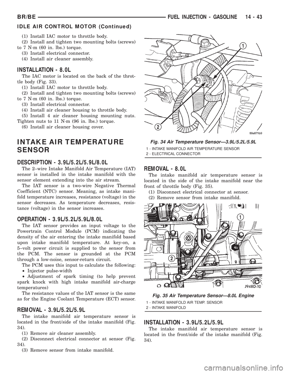
The intake manifold air temperature sensor is
located in the front/side of the intake manifold (Fig.
34).
(1) Remove air cleaner assembly.
(2) Disconnect electrical connector at sensor (Fig.
34).
(3) Remove sensor from intake manifold.
REMOVAL - 8.0L
The intake manifold air temperature sensor is
located in the side of the intake manifold near the
front of throttle body (Fig. 35).
(1) Disconnect electrical connector at sensor.
(2) Remove sensor from intake manifold.
INSTALLATION - 3.9L/5.2L/5.9L
The intake manifold air temperature sensor is
located in the front/side of the intake manifold (Fig.
34).
Fig. 34 Air Temperature SensorÐ3.9L/5.2L/5.9L
1 - INTAKE MANIFOLD AIR TEMPERATURE SENSOR
2 - ELECTRICAL CONNECTOR
Fig. 35 Air Temperature SensorÐ8.0L Engine
1 - INTAKE MANIFOLD AIR TEMP. SENSOR
2 - INTAKE MANIFOLD
BR/BEFUEL INJECTION - GASOLINE 14 - 43
IDLE AIR CONTROL MOTOR (Continued)
Page 1542 of 2889
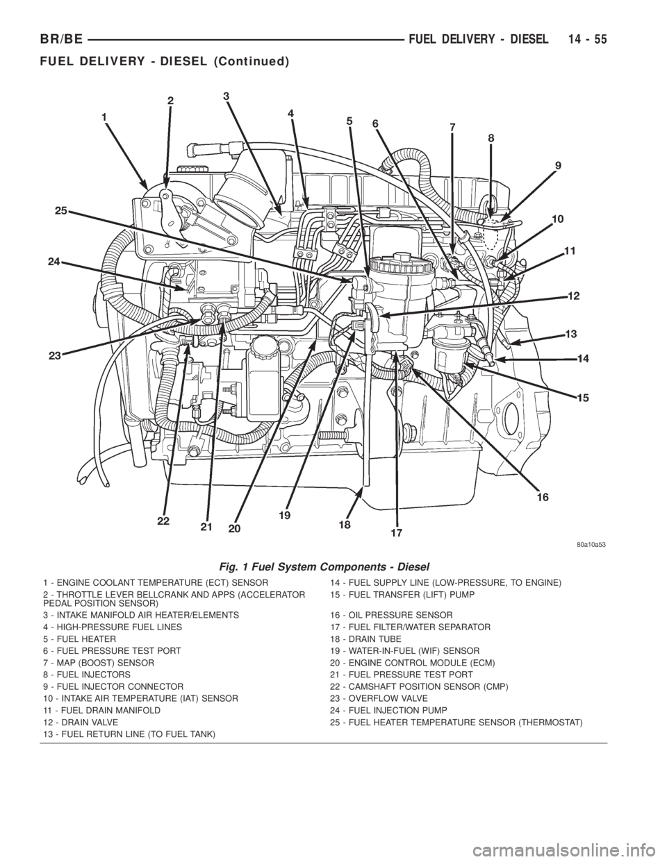
Fig. 1 Fuel System Components - Diesel
1 - ENGINE COOLANT TEMPERATURE (ECT) SENSOR 14 - FUEL SUPPLY LINE (LOW-PRESSURE, TO ENGINE)
2 - THROTTLE LEVER BELLCRANK AND APPS (ACCELERATOR
PEDAL POSITION SENSOR)15 - FUEL TRANSFER (LIFT) PUMP
3 - INTAKE MANIFOLD AIR HEATER/ELEMENTS 16 - OIL PRESSURE SENSOR
4 - HIGH-PRESSURE FUEL LINES 17 - FUEL FILTER/WATER SEPARATOR
5 - FUEL HEATER 18 - DRAIN TUBE
6 - FUEL PRESSURE TEST PORT 19 - WATER-IN-FUEL (WIF) SENSOR
7 - MAP (BOOST) SENSOR 20 - ENGINE CONTROL MODULE (ECM)
8 - FUEL INJECTORS 21 - FUEL PRESSURE TEST PORT
9 - FUEL INJECTOR CONNECTOR 22 - CAMSHAFT POSITION SENSOR (CMP)
10 - INTAKE AIR TEMPERATURE (IAT) SENSOR 23 - OVERFLOW VALVE
11 - FUEL DRAIN MANIFOLD 24 - FUEL INJECTION PUMP
12 - DRAIN VALVE 25 - FUEL HEATER TEMPERATURE SENSOR (THERMOSTAT)
13 - FUEL RETURN LINE (TO FUEL TANK)
BR/BEFUEL DELIVERY - DIESEL 14 - 55
FUEL DELIVERY - DIESEL (Continued)
Page 1575 of 2889
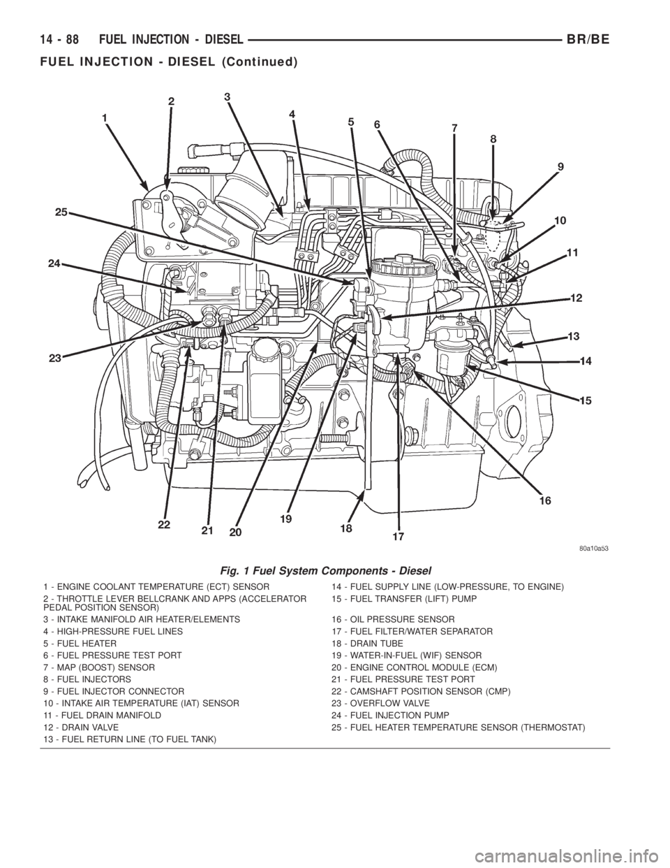
Fig. 1 Fuel System Components - Diesel
1 - ENGINE COOLANT TEMPERATURE (ECT) SENSOR 14 - FUEL SUPPLY LINE (LOW-PRESSURE, TO ENGINE)
2 - THROTTLE LEVER BELLCRANK AND APPS (ACCELERATOR
PEDAL POSITION SENSOR)15 - FUEL TRANSFER (LIFT) PUMP
3 - INTAKE MANIFOLD AIR HEATER/ELEMENTS 16 - OIL PRESSURE SENSOR
4 - HIGH-PRESSURE FUEL LINES 17 - FUEL FILTER/WATER SEPARATOR
5 - FUEL HEATER 18 - DRAIN TUBE
6 - FUEL PRESSURE TEST PORT 19 - WATER-IN-FUEL (WIF) SENSOR
7 - MAP (BOOST) SENSOR 20 - ENGINE CONTROL MODULE (ECM)
8 - FUEL INJECTORS 21 - FUEL PRESSURE TEST PORT
9 - FUEL INJECTOR CONNECTOR 22 - CAMSHAFT POSITION SENSOR (CMP)
10 - INTAKE AIR TEMPERATURE (IAT) SENSOR 23 - OVERFLOW VALVE
11 - FUEL DRAIN MANIFOLD 24 - FUEL INJECTION PUMP
12 - DRAIN VALVE 25 - FUEL HEATER TEMPERATURE SENSOR (THERMOSTAT)
13 - FUEL RETURN LINE (TO FUEL TANK)
14 - 88 FUEL INJECTION - DIESELBR/BE
FUEL INJECTION - DIESEL (Continued)
Page 1576 of 2889
DIAGNOSIS AND TESTING - BOOST PRESSURE
Two pressure gauges attached at two different
points are required for this test.(1) Obtain two 6828 fuel pressure test gauges
(equivalent gauges are OK).Gauge Consistency
Test:Connect the gauges together to a common pres-
sure source and verify pressure consistency of both
gauges. Do this consistency test at approximately 206
kPa (30 psi). If pressures are different, they can still
be used for test. Note and record differences in pres-
sures before testing. Make adjustments as necessary.
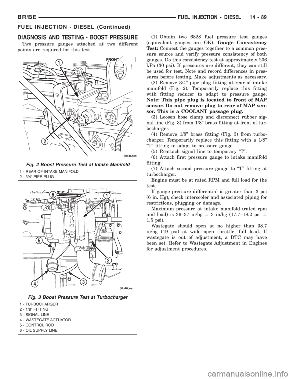
(2) Remove 3/4º pipe plug fitting at rear of intake
manifold (Fig. 2). Temporarily replace this fitting
with fitting reducer to adapt to pressure gauge.
Note: This pipe plug is located to front of MAP
sensor. Do not remove plug to rear of MAP sen-
sor. This is a COOLANT passage plug.
(3) Loosen hose clamp and disconnect rubber sig-
nal line (Fig. 3) from 1/8º brass fitting at front of tur-
bocharger.
(4) Remove 1/8º brass fitting (Fig. 3) from turbo-
charger. Temporarily replace this fitting with a 1/8º
ªTº fitting to adapt to pressure gauge.
(5) Reattach signal line to temporary ªTº.
(6) Attach first pressure gauge to intake manifold
fitting.
(7) Attach second pressure gauge to ªTº fitting at
turbocharger.
Engine must be at rated RPM and full load for the
test.
If gauge pressure differential is greater than 3 psi
(6 in. Hg), check intercooler and associated piping for
restrictions, plugging or damage.
Maximum pressure at intake manifold (rated rpm
and load) is 36±37 in/hg63 in/hg (17.7±18.2 psi6
1.5 psi).
Wastegate should open at no higher than 38.7
in/hg (19 psi) at wide open throttle, full load. If
wastegate is out of adjustment, a DTC may have
been set. Refer to Wastegate Adjustment in Engines
for adjustment procedures.
Fig. 2 Boost Pressure Test at Intake Manifold
1 - REAR OF INTAKE MANIFOLD
2 - 3/49PIPE PLUG
Fig. 3 Boost Pressure Test at Turbocharger
1 - TURBOCHARGER
2 - 1/89FITTING
3 - SIGNAL LINE
4 - WASTEGATE ACTUATOR
5 - CONTROL ROD
6 - OIL SUPPLY LINE
BR/BEFUEL INJECTION - DIESEL 14 - 89
FUEL INJECTION - DIESEL (Continued)
Page 1577 of 2889
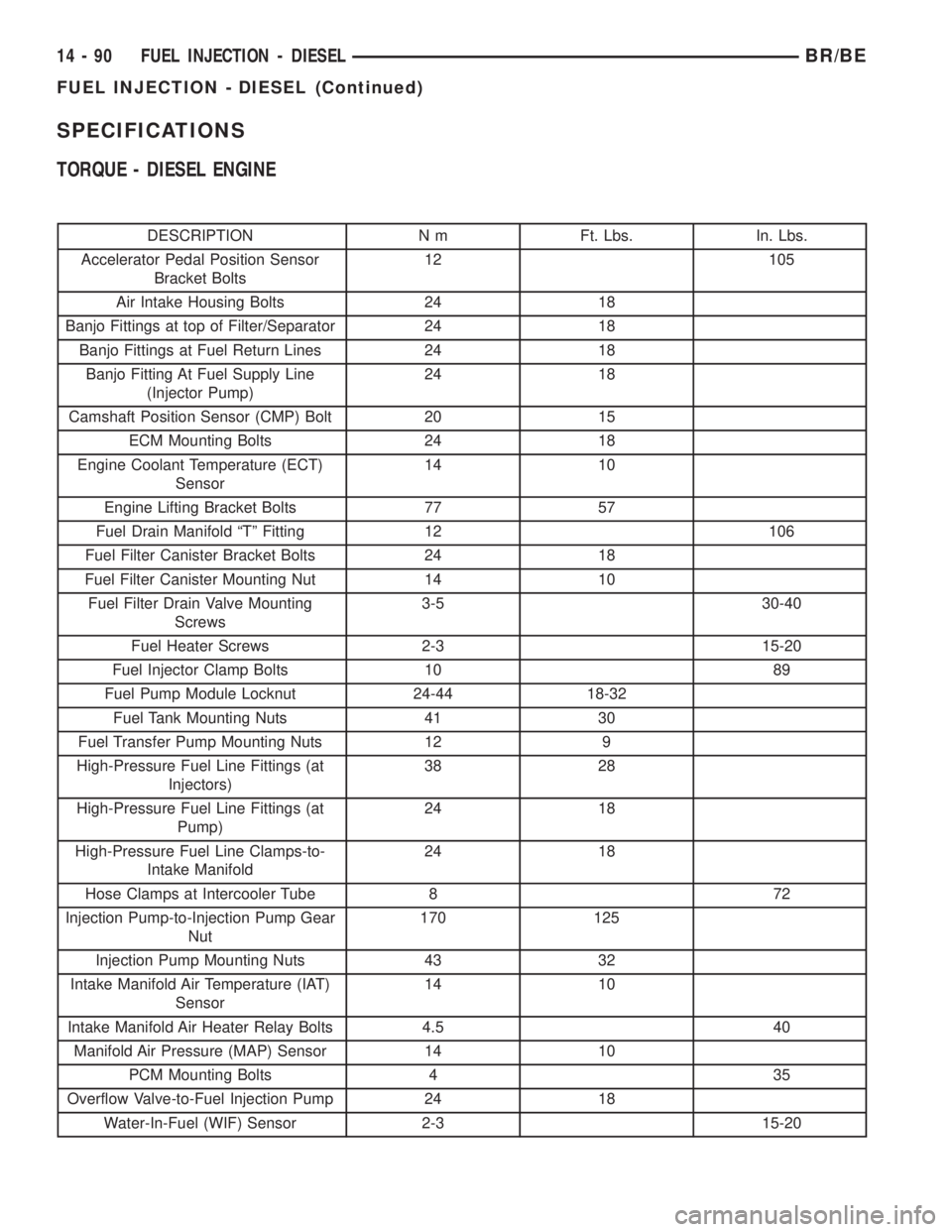
SPECIFICATIONS
TORQUE - DIESEL ENGINE
DESCRIPTION N m Ft. Lbs. In. Lbs.
Accelerator Pedal Position Sensor
Bracket Bolts12 105
Air Intake Housing Bolts 24 18
Banjo Fittings at top of Filter/Separator 24 18
Banjo Fittings at Fuel Return Lines 24 18
Banjo Fitting At Fuel Supply Line
(Injector Pump)24 18
Camshaft Position Sensor (CMP) Bolt 20 15
ECM Mounting Bolts 24 18
Engine Coolant Temperature (ECT)
Sensor14 10
Engine Lifting Bracket Bolts 77 57
Fuel Drain Manifold ªTº Fitting 12 106
Fuel Filter Canister Bracket Bolts 24 18
Fuel Filter Canister Mounting Nut 14 10
Fuel Filter Drain Valve Mounting
Screws3-5 30-40
Fuel Heater Screws 2-3 15-20
Fuel Injector Clamp Bolts 10 89
Fuel Pump Module Locknut 24-44 18-32
Fuel Tank Mounting Nuts 41 30
Fuel Transfer Pump Mounting Nuts 12 9
High-Pressure Fuel Line Fittings (at
Injectors)38 28
High-Pressure Fuel Line Fittings (at
Pump)24 18
High-Pressure Fuel Line Clamps-to-
Intake Manifold24 18
Hose Clamps at Intercooler Tube 8 72
Injection Pump-to-Injection Pump Gear
Nut170 125
Injection Pump Mounting Nuts 43 32
Intake Manifold Air Temperature (IAT)
Sensor14 10
Intake Manifold Air Heater Relay Bolts 4.5 40
Manifold Air Pressure (MAP) Sensor 14 10
PCM Mounting Bolts 4 35
Overflow Valve-to-Fuel Injection Pump 24 18
Water-In-Fuel (WIF) Sensor 2-3 15-20
14 - 90 FUEL INJECTION - DIESELBR/BE
FUEL INJECTION - DIESEL (Continued)
Page 1626 of 2889
(8) Fill the system with fluid and perform Steering
Pump Initial Operation, (Refer to 19 - STEERING/
PUMP - STANDARD PROCEDURE).
(9) Start the engine and run it for fifteen minutes
then stop the engine.
(10) Remove the return line/lines from the pump
and plug the pump port/ports.
(11) Pour fresh fluid into the reservoir and check
the draining fluid for contamination. If the fluid is
still contaminated, disassemble and clean the steer-
ing gear and flush the system again.
(12) Install the return line/lines and perform
Steering Pump Initial Operation, (Refer to 19 -
STEERING/PUMP - STANDARD PROCEDURE).
REMOVAL - GASOLINE ENGINE
(1) Remove the serpentine drive belt, (Refer to 7 -
COOLING/ACCESSORY DRIVE/DRIVE BELTS -
REMOVAL) OR (Refer to 7 - COOLING/ACCESSORY
DRIVE/DRIVE BELTS - REMOVAL).
(2) Remove the hoses from the power steering
pump and cap the fittings.
(3) Remove battery ground cable and unthread
stud from cylinder head, do not remove from bracket.
(4) Loosen upper bracket bolt and remove the
lower bracket to engine block bolts.
(5) Pivot the pump assembly past the coolant tube.
(6) Remove the upper stud and remove upper bolt
from cylinder head.
(7) Remove steering pump and mounting bracket
from engine as an assembly.
(8) Remove the pump pulley with Puller C-4333, to
access pump attaching bolts, (Refer to 19 - STEER-
ING/PUMP/PULLEY - REMOVAL).
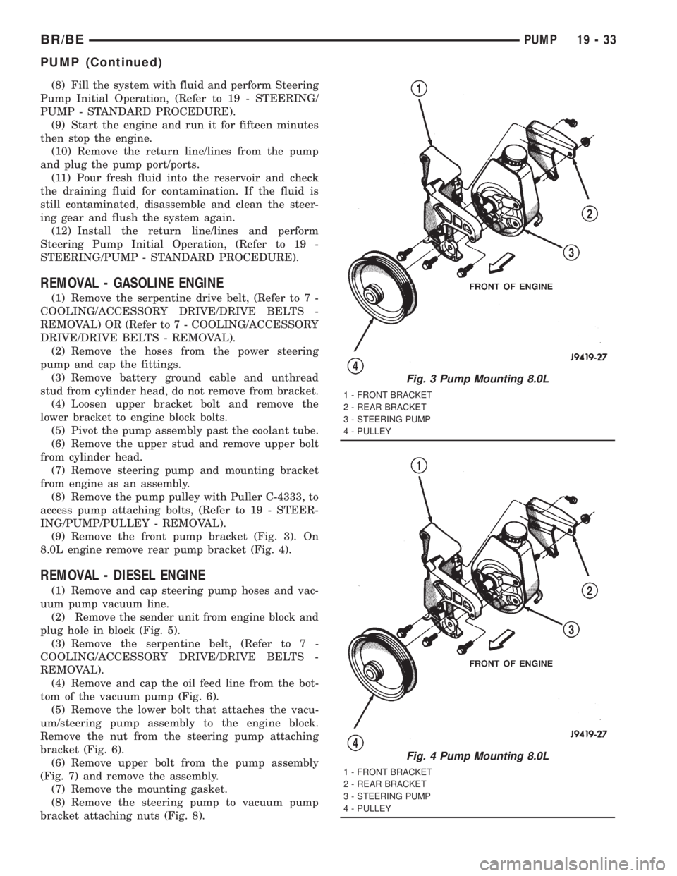
(9) Remove the front pump bracket (Fig. 3). On
8.0L engine remove rear pump bracket (Fig. 4).
REMOVAL - DIESEL ENGINE
(1) Remove and cap steering pump hoses and vac-
uum pump vacuum line.
(2) Remove the sender unit from engine block and
plug hole in block (Fig. 5).
(3) Remove the serpentine belt, (Refer to 7 -
COOLING/ACCESSORY DRIVE/DRIVE BELTS -
REMOVAL).
(4) Remove and cap the oil feed line from the bot-
tom of the vacuum pump (Fig. 6).
(5) Remove the lower bolt that attaches the vacu-
um/steering pump assembly to the engine block.
Remove the nut from the steering pump attaching
bracket (Fig. 6).
(6) Remove upper bolt from the pump assembly
(Fig. 7) and remove the assembly.
(7) Remove the mounting gasket.
(8) Remove the steering pump to vacuum pump
bracket attaching nuts (Fig. 8).
Fig. 3 Pump Mounting 8.0L
1 - FRONT BRACKET
2 - REAR BRACKET
3 - STEERING PUMP
4 - PULLEY
Fig. 4 Pump Mounting 8.0L
1 - FRONT BRACKET
2 - REAR BRACKET
3 - STEERING PUMP
4 - PULLEY
BR/BEPUMP 19 - 33
PUMP (Continued)
Page 1628 of 2889
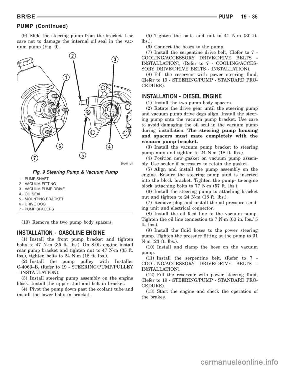
(9) Slide the steering pump from the bracket. Use
care not to damage the internal oil seal in the vac-
uum pump (Fig. 9).
(10) Remove the two pump body spacers.
INSTALLATION - GASOLINE ENGINE
(1) Install the front pump bracket and tighten
bolts to 47 N´m (35 ft. lbs.). On 8.0L engine install
rear pump bracket and tighten nut to 47 N´m (35 ft.
lbs.), tighten bolts to 24 N´m (18 ft. lbs.).
(2) Install the pump pulley with Installer
C-4063±B, (Refer to 19 - STEERING/PUMP/PULLEY
- INSTALLATION).
(3) Install steering pump assembly on the engine
block. Install the upper stud and bolt in bracket.
(4) Pivot the pump down past the coolant tube and
install the lower bolts in bracket.(5) Tighten the bolts and nut to 41 N´m (30 ft.
lbs.).
(6) Connect the hoses to the pump.
(7) Install the serpentine drive belt, (Refer to 7 -
COOLING/ACCESSORY DRIVE/DRIVE BELTS -
INSTALLATION), (Refer to 7 - COOLING/ACCES-
SORY DRIVE/DRIVE BELTS - INSTALLATION).
(8) Fill the reservoir with power steering fluid,
(Refer to 19 - STEERING/PUMP - STANDARD PRO-
CEDURE).
INSTALLATION - DIESEL ENGINE
(1) Install the two pump body spacers.
(2) Rotate the drive gear until the steering pump
and vacuum pump drive dogs align. Install the steer-
ing pump onto the vacuum pump bracket. Use care
to avoid damaging the oil seal in the vacuum pump
during installation.The steering pump housing
and spacers must mate completely with the
vacuum pump bracket.
(3) Install the vacuum pump bracket to steering
pump nuts and tighten to 24 N´m (18 ft. lbs.).
(4) Position new gasket on vacuum pump assem-
bly. Use sealer if necessary to retain the gasket.
(5) Align and install the pump assembly on the
engine. Ensure the steering pump stud is inserted
into the block bracket. Tighten the pump- to-engine
block attaching bolts to 77 N´m (57 ft. lbs.).
(6) Install the steering pump to attaching bracket
nut and tighten to 24 N´m (18 ft. lbs.).
(7) Remove plug and install the oil pressure send-
ing unit and electrical connector.
(8) Install the oil feed line to the vacuum pump.
Tighten the oil line connection to 7 N´m (60 in. lbs./ 5
ft. lbs.).
(9) Install the fluid hoses to the power steering
pump. Tighten the pressure fitting at the pump to 31
N´m (23 ft. lbs.).
(10) Install and clamp the hose on the vacuum
pump.
(11) Install the serpentine belt, (Refer to 7 -
COOLING/ACCESSORY DRIVE/DRIVE BELTS -
INSTALLATION).
(12) Fill the reservoir with power steering fluid,
(Refer to 19 - STEERING/PUMP - STANDARD PRO-
CEDURE).
(13) Start the engine and check the operation of
the brakes.
Fig. 9 Steering Pump & Vacuum Pump
1 - PUMP SHAFT
2 - VACUUM FITTING
3 - VACUUM PUMP DRIVE
4 - OIL SEAL
5 - MOUNTING BRACKET
6 - DRIVE DOG
7 - PUMP SPACERS
BR/BEPUMP 19 - 35
PUMP (Continued)