2001 DODGE RAM service indicator
[x] Cancel search: service indicatorPage 1638 of 2889
The driver selects a particular gear by moving the
shift lever to the desired gear position. This move-
ment moves the internal transmission shift compo-
nents to begin the shift sequence. As the shift lever
moves the selected shift rail, the shift fork attached
to that rail begins to move. The fork is positioned in
a groove in the outer circumference of the synchro-
nizer sleeve. As the shift fork moves the synchronizer
sleeve, the synchronizer begins to speed-up or slow
down the selected gear (depending on whether we are
up-shifting or down-shifting). The synchronizer does
this by having the synchronizer hub splined to the
mainshaft, or the countershaft in some cases, and
moving the blocker ring into contact with the gear's
friction cone. As the blocker ring and friction cone
come together, the gear speed is brought up or down
to the speed of the synchronizer. As the two speeds
match, the splines on the inside of the synchronizer
sleeve become aligned with the teeth on the blocker
ring and the friction cone and eventually will slide
over the teeth, locking the gear to the mainshaft, or
countershaft, through the synchronizer.
DIAGNOSIS AND TESTING - MANUAL
TRANSMISSION
LOW LUBRICANT LEVEL
A low transmission lubricant level is generally the
result of a leak, inadequate lubricant fill or an incor-
rect lubricant level check.
Leaks can occur at the mating surfaces of the gear
case, adaptor or extension housing, or from the front/
rear seals. A suspected leak could also be the result
of an overfill condition.
Leaks at the rear of the extension or adapter hous-
ing will be from the housing oil seals. Leaks at com-
ponent mating surfaces will probably be the result of
inadequate sealer, gaps in the sealer, incorrect bolt
tightening or use of a non-recommended sealer.
A leak at the front of the transmission will be from
either the front bearing retainer or retainer seal.
Lubricant may be seen dripping from the clutch
housing after extended operation. If the leak is
severe, it may also contaminate the clutch disc caus-
ing the disc to slip, grab and or chatter.
A correct lubricant level check can only be made
when the vehicle is level. Also allow the lubricant to
settle for a minute or so before checking. These rec-
ommendations will ensure an accurate check and
avoid an underfill or overfill condition. Always check
the lubricant level after any addition of fluid to avoid
an incorrect lubricant level condition.
HARD SHIFTING
Hard shifting is usually caused by a low lubricant
level, improper or contaminated lubricants. The con-sequence of using non-recommended lubricants is
noise, excessive wear, internal bind and hard shift-
ing. Substantial lubricant leaks can result in gear,
shift rail, synchro, and bearing damage. If a leak
goes undetected for an extended period, the first indi-
cations of component damage are usually hard shift-
ing and noise.
Component damage, incorrect clutch adjustment or
damaged clutch pressure plate or disc are additional
probable causes of increased shift effort. Incorrect
adjustment or a worn/damaged pressure plate or disc
can cause incorrect release. If clutch problem is
advanced, gear clash during shifts can result. Worn
or damaged synchro rings can cause gear clash when
shifting into any forward gear. In some new or
rebuilt transmissions, new synchro rings may tend to
stick slightly causing hard or noisy shifts. In most
cases this condition will decline as the rings wear-in.
TRANSMISSION NOISE
Most manual transmissions make some noise dur-
ing normal operation. Rotating gears generate a mild
whine that is audible, but generally only at extreme
speeds.
Severe highly audible transmission noise is gener-
ally the initial indicator of a lubricant problem.
Insufficient, improper or contaminated lubricant will
promote rapid wear of gears, synchros, shift rails,
forks and bearings. The overheating caused by a
lubricant problem, can also lead to gear breakage.
REMOVAL
(1) Disconnect battery negative cable.
(2) Shift transmission into Neutral.
(3) Remove shift boot bezel screws and slide boot
upward on shift lever extension.
(4) Remove shift lever extension from the shift
tower and lever assembly.
(5) Remove bolts attaching shift tower and lever
assembly to rear case. Then remove shift tower and
lever assembly.
(6) Raise vehicle on hoist.
(7) Remove crankshaft position sensor. Retain sen-
sor attaching bolts.
(8) Remove skid plate, if equipped.
(9) Drain transmission lubricant if transmission
will be disassembled for service.
(10) Mark propeller shaft/shafts and yoke/yokes for
installation reference and remove propeller shaft/
shafts.
(11) Disengage harness from clips on transmission
housing.
(12) Support engine with adjustable jack stand
and wood block.
(13) Drain transmission lubricant if transmission
will be disassembled for service.
BR/BEMANUAL - NV3500 21 - 3
MANUAL - NV3500 (Continued)
Page 1795 of 2889
ELINE/PROPELLER SHAFT/PROPELLER SHAFT -
REMOVAL)
(12) Disconnect wires from park/neutral position
switch and transmission solenoid.
(13) Disconnect gearshift rod and torque shaft
assembly from transmission.
(14) Disconnect throttle valve cable from transmis-
sion bracket and throttle valve lever.
(15) On4x4models, disconnect shift rod from
transfer case shift lever.
(16)
Support rear of engine with safety stand or jack.
(17) Raise transmission slightly with service jack
to relieve load on crossmember and supports.
(18) Remove bolts securing rear support and cush-
ion to transmission and crossmember. Raise trans-
mission slightly, slide exhaust hanger arm from
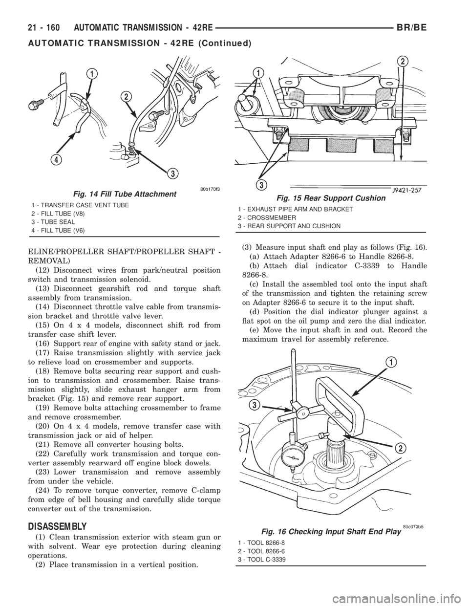
bracket (Fig. 15) and remove rear support.
(19) Remove bolts attaching crossmember to frame
and remove crossmember.
(20) On4x4models, remove transfer case with
transmission jack or aid of helper.
(21) Remove all converter housing bolts.
(22) Carefully work transmission and torque con-
verter assembly rearward off engine block dowels.
(23) Lower transmission and remove assembly
from under the vehicle.
(24) To remove torque converter, remove C-clamp
from edge of bell housing and carefully slide torque
converter out of the transmission.
DISASSEMBLY
(1) Clean transmission exterior with steam gun or
with solvent. Wear eye protection during cleaning
operations.
(2) Place transmission in a vertical position.(3)
Measure input shaft end play as follows (Fig. 16).
(a) Attach Adapter 8266-6 to Handle 8266-8.
(b) Attach dial indicator C-3339 to Handle
8266-8.
(c)
Install the assembled tool onto the input shaft
of the transmission and tighten the retaining screw
on Adapter 8266-6 to secure it to the input shaft.
(d)Position the dial indicator plunger against a
flat spot on the oil pump and zero the dial indicator.
(e) Move the input shaft in and out. Record the
maximum travel for assembly reference.
Fig. 14 Fill Tube Attachment
1 - TRANSFER CASE VENT TUBE
2 - FILL TUBE (V8)
3 - TUBE SEAL
4 - FILL TUBE (V6)Fig. 15 Rear Support Cushion
1 - EXHAUST PIPE ARM AND BRACKET
2 - CROSSMEMBER
3 - REAR SUPPORT AND CUSHION
Fig. 16 Checking Input Shaft End Play
1 - TOOL 8266-8
2 - TOOL 8266-6
3 - TOOL C-3339
21 - 160 AUTOMATIC TRANSMISSION - 42REBR/BE
AUTOMATIC TRANSMISSION - 42RE (Continued)
Page 1966 of 2889
(17) Raise transmission slightly with service jack
to relieve load on crossmember and supports.
(18) Remove bolts securing rear support and cush-
ion to transmission and crossmember. Raise trans-
mission slightly, slide exhaust hanger arm from
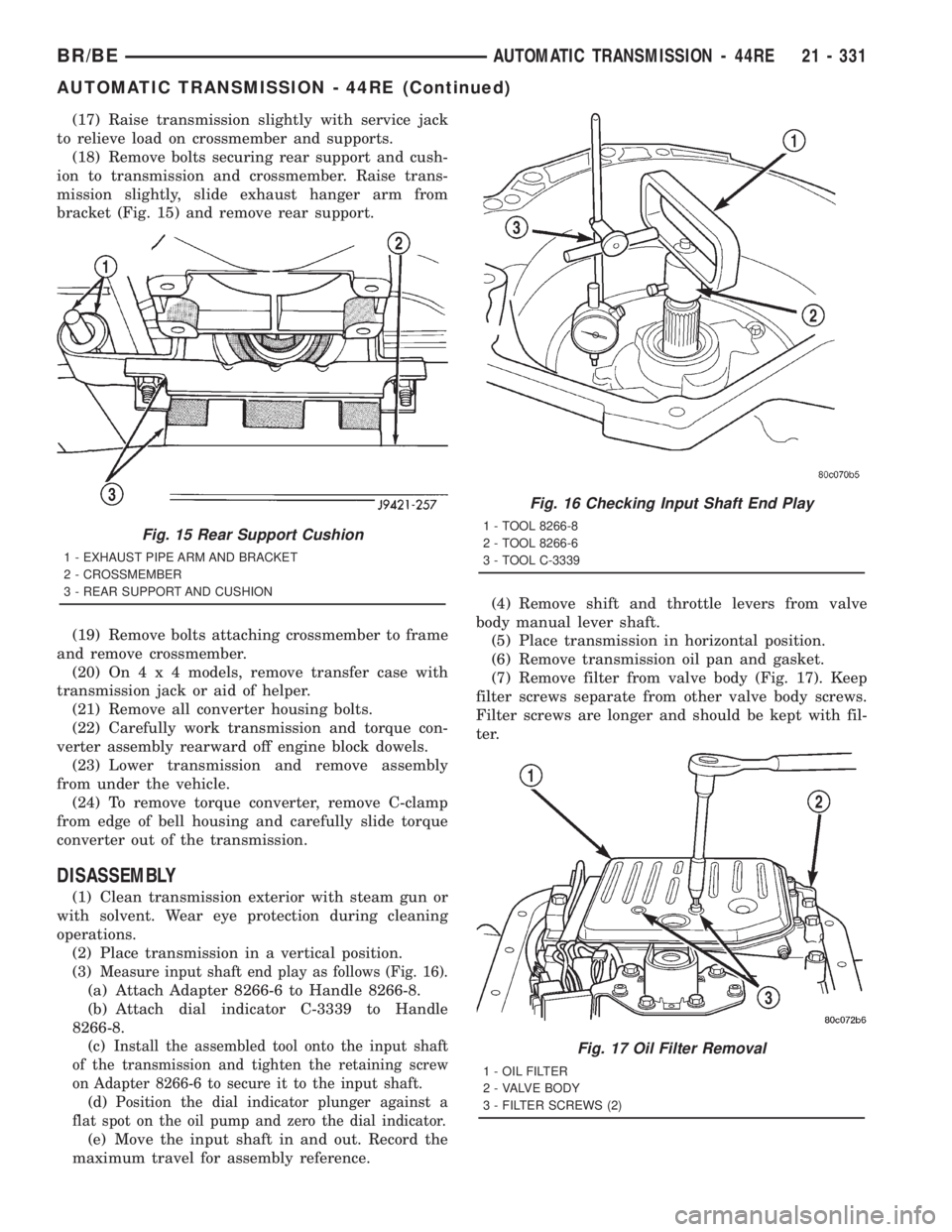
bracket (Fig. 15) and remove rear support.
(19) Remove bolts attaching crossmember to frame
and remove crossmember.
(20) On4x4models, remove transfer case with
transmission jack or aid of helper.
(21) Remove all converter housing bolts.
(22) Carefully work transmission and torque con-
verter assembly rearward off engine block dowels.
(23) Lower transmission and remove assembly
from under the vehicle.
(24) To remove torque converter, remove C-clamp
from edge of bell housing and carefully slide torque
converter out of the transmission.
DISASSEMBLY
(1) Clean transmission exterior with steam gun or
with solvent. Wear eye protection during cleaning
operations.
(2) Place transmission in a vertical position.
(3)
Measure input shaft end play as follows (Fig. 16).
(a) Attach Adapter 8266-6 to Handle 8266-8.
(b) Attach dial indicator C-3339 to Handle
8266-8.
(c)
Install the assembled tool onto the input shaft
of the transmission and tighten the retaining screw
on Adapter 8266-6 to secure it to the input shaft.
(d)Position the dial indicator plunger against a
flat spot on the oil pump and zero the dial indicator.
(e) Move the input shaft in and out. Record the
maximum travel for assembly reference.(4) Remove shift and throttle levers from valve
body manual lever shaft.
(5) Place transmission in horizontal position.
(6) Remove transmission oil pan and gasket.
(7) Remove filter from valve body (Fig. 17). Keep
filter screws separate from other valve body screws.
Filter screws are longer and should be kept with fil-
ter.
Fig. 15 Rear Support Cushion
1 - EXHAUST PIPE ARM AND BRACKET
2 - CROSSMEMBER
3 - REAR SUPPORT AND CUSHION
Fig. 16 Checking Input Shaft End Play
1 - TOOL 8266-8
2 - TOOL 8266-6
3 - TOOL C-3339
Fig. 17 Oil Filter Removal
1 - OIL FILTER
2 - VALVE BODY
3 - FILTER SCREWS (2)
BR/BEAUTOMATIC TRANSMISSION - 44RE 21 - 331
AUTOMATIC TRANSMISSION - 44RE (Continued)
Page 2138 of 2889
(12) Disconnect wires from park/neutral position
switch and transmission solenoid.
(13) Disconnect gearshift rod and torque shaft
assembly from transmission.
(14) Disconnect throttle valve cable from transmis-
sion bracket and throttle valve lever.
(15) On4x4models, disconnect shift rod from
transfer case shift lever.
(16)
Support rear of engine with safety stand or jack.
(17) Raise transmission slightly with service jack
to relieve load on crossmember and supports.
(18) Remove bolts securing rear support and cush-
ion to transmission and crossmember. Raise trans-
mission slightly, slide exhaust hanger arm from
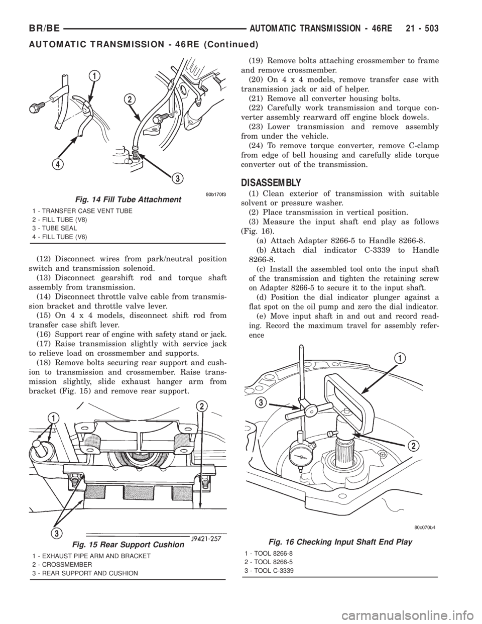
bracket (Fig. 15) and remove rear support.(19) Remove bolts attaching crossmember to frame
and remove crossmember.
(20) On4x4models, remove transfer case with
transmission jack or aid of helper.
(21) Remove all converter housing bolts.
(22) Carefully work transmission and torque con-
verter assembly rearward off engine block dowels.
(23) Lower transmission and remove assembly
from under the vehicle.
(24) To remove torque converter, remove C-clamp
from edge of bell housing and carefully slide torque
converter out of the transmission.
DISASSEMBLY
(1) Clean exterior of transmission with suitable
solvent or pressure washer.
(2) Place transmission in vertical position.
(3) Measure the input shaft end play as follows
(Fig. 16).
(a) Attach Adapter 8266-5 to Handle 8266-8.
(b) Attach dial indicator C-3339 to Handle
8266-8.
(c)
Install the assembled tool onto the input shaft
of the transmission and tighten the retaining screw
on Adapter 8266-5 to secure it to the input shaft.
(d)Position the dial indicator plunger against a
flat spot on the oil pump and zero the dial indicator.
(e)Move input shaft in and out and record read-
ing. Record the maximum travel for assembly refer-
ence
Fig. 14 Fill Tube Attachment
1 - TRANSFER CASE VENT TUBE
2 - FILL TUBE (V8)
3 - TUBE SEAL
4 - FILL TUBE (V6)
Fig. 15 Rear Support Cushion
1 - EXHAUST PIPE ARM AND BRACKET
2 - CROSSMEMBER
3 - REAR SUPPORT AND CUSHION
Fig. 16 Checking Input Shaft End Play
1 - TOOL 8266-8
2 - TOOL 8266-5
3 - TOOL C-3339
BR/BEAUTOMATIC TRANSMISSION - 46RE 21 - 503
AUTOMATIC TRANSMISSION - 46RE (Continued)
Page 2309 of 2889
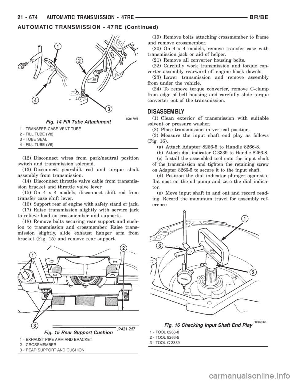
(12) Disconnect wires from park/neutral position
switch and transmission solenoid.
(13) Disconnect gearshift rod and torque shaft
assembly from transmission.
(14) Disconnect throttle valve cable from transmis-
sion bracket and throttle valve lever.
(15) On4x4models, disconnect shift rod from
transfer case shift lever.
(16)
Support rear of engine with safety stand or jack.
(17) Raise transmission slightly with service jack
to relieve load on crossmember and supports.
(18) Remove bolts securing rear support and cush-
ion to transmission and crossmember. Raise trans-
mission slightly, slide exhaust hanger arm from
bracket (Fig. 15) and remove rear support.(19) Remove bolts attaching crossmember to frame
and remove crossmember.
(20) On4x4models, remove transfer case with
transmission jack or aid of helper.
(21) Remove all converter housing bolts.
(22) Carefully work transmission and torque con-
verter assembly rearward off engine block dowels.
(23) Lower transmission and remove assembly
from under the vehicle.
(24) To remove torque converter, remove C-clamp
from edge of bell housing and carefully slide torque
converter out of the transmission.
DISASSEMBLY
(1) Clean exterior of transmission with suitable
solvent or pressure washer.
(2) Place transmission in vertical position.
(3) Measure the input shaft end play as follows
(Fig. 16).
(a) Attach Adapter 8266-5 to Handle 8266-8.
(b)
Attach dial indicator C-3339 to Handle 8266-8.
(c)Install the assembled tool onto the input shaft
of the transmission and tighten the retaining screw
on Adapter 8266-5 to secure it to the input shaft.
(d) Position the dial indicator plunger against a
flat spot on the oil pump and zero the dial indica-
tor.
(e) Move input shaft in and out and record read-
ing. Record the maximum travel for assembly ref-
erence
Fig. 14 Fill Tube Attachment
1 - TRANSFER CASE VENT TUBE
2 - FILL TUBE (V8)
3 - TUBE SEAL
4 - FILL TUBE (V6)
Fig. 15 Rear Support Cushion
1 - EXHAUST PIPE ARM AND BRACKET
2 - CROSSMEMBER
3 - REAR SUPPORT AND CUSHION
Fig. 16 Checking Input Shaft End Play
1 - TOOL 8266-8
2 - TOOL 8266-5
3 - TOOL C-3339
21 - 674 AUTOMATIC TRANSMISSION - 47REBR/BE
AUTOMATIC TRANSMISSION - 47RE (Continued)
Page 2563 of 2889
METHOD 2 (RELOCATE TIRE ON WHEEL)
NOTE: Rotating the tire on wheel is particularly
effective when there is runout in both tire and
wheel.
(1) Remove tire from wheel and mount wheel on
service dynamic balance machine.
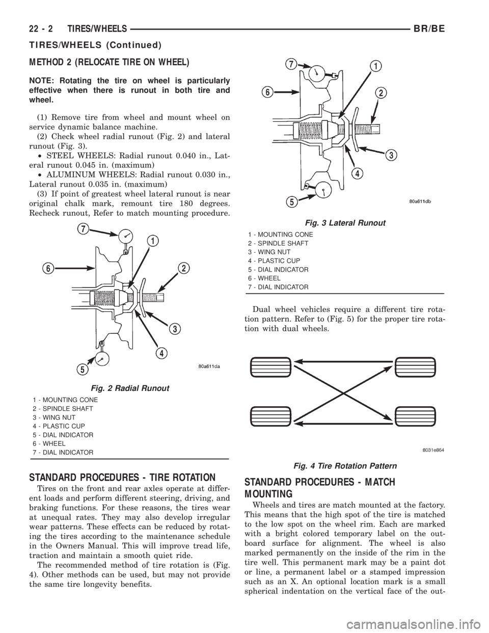
(2) Check wheel radial runout (Fig. 2) and lateral
runout (Fig. 3).
²STEEL WHEELS: Radial runout 0.040 in., Lat-
eral runout 0.045 in. (maximum)
²ALUMINUM WHEELS: Radial runout 0.030 in.,
Lateral runout 0.035 in. (maximum)
(3) If point of greatest wheel lateral runout is near
original chalk mark, remount tire 180 degrees.
Recheck runout, Refer to match mounting procedure.
STANDARD PROCEDURES - TIRE ROTATION
Tires on the front and rear axles operate at differ-
ent loads and perform different steering, driving, and
braking functions. For these reasons, the tires wear
at unequal rates. They may also develop irregular
wear patterns. These effects can be reduced by rotat-
ing the tires according to the maintenance schedule
in the Owners Manual. This will improve tread life,
traction and maintain a smooth quiet ride.
The recommended method of tire rotation is (Fig.
4). Other methods can be used, but may not provide
the same tire longevity benefits.Dual wheel vehicles require a different tire rota-
tion pattern. Refer to (Fig. 5) for the proper tire rota-
tion with dual wheels.STANDARD PROCEDURES - MATCH
MOUNTING
Wheels and tires are match mounted at the factory.
This means that the high spot of the tire is matched
to the low spot on the wheel rim. Each are marked
with a bright colored temporary label on the out-
board surface for alignment. The wheel is also
marked permanently on the inside of the rim in the
tire well. This permanent mark may be a paint dot
or line, a permanent label or a stamped impression
such as an X. An optional location mark is a small
spherical indentation on the vertical face of the out-
Fig. 2 Radial Runout
1 - MOUNTING CONE
2 - SPINDLE SHAFT
3 - WING NUT
4 - PLASTIC CUP
5 - DIAL INDICATOR
6 - WHEEL
7 - DIAL INDICATOR
Fig. 3 Lateral Runout
1 - MOUNTING CONE
2 - SPINDLE SHAFT
3 - WING NUT
4 - PLASTIC CUP
5 - DIAL INDICATOR
6 - WHEEL
7 - DIAL INDICATOR
Fig. 4 Tire Rotation Pattern
22 - 2 TIRES/WHEELSBR/BE
TIRES/WHEELS (Continued)
Page 2564 of 2889
board flange on some non styled base steel wheels.
The tire must be removed to locate the permanent
mark on the inside of the wheel.
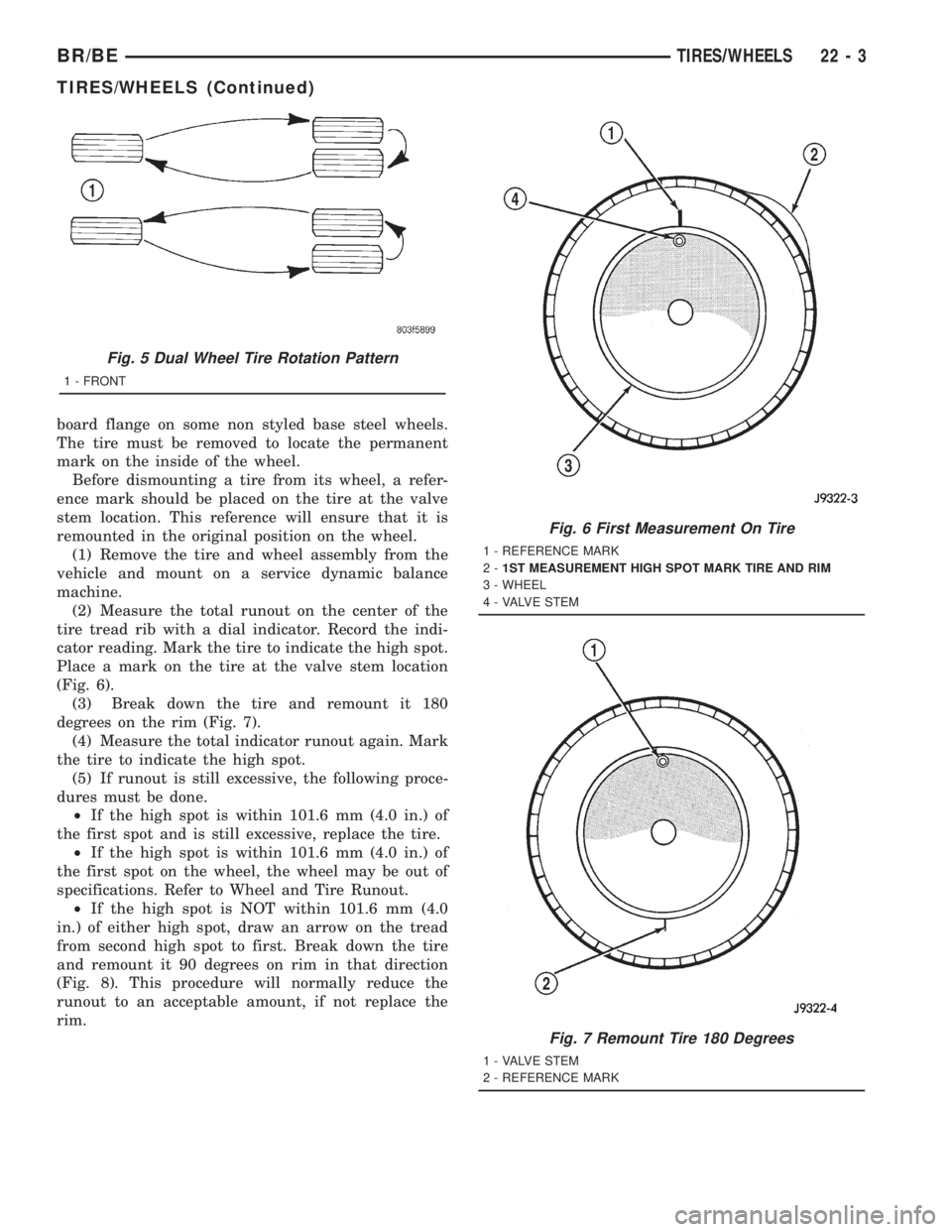
Before dismounting a tire from its wheel, a refer-
ence mark should be placed on the tire at the valve
stem location. This reference will ensure that it is
remounted in the original position on the wheel.
(1) Remove the tire and wheel assembly from the
vehicle and mount on a service dynamic balance
machine.
(2) Measure the total runout on the center of the
tire tread rib with a dial indicator. Record the indi-
cator reading. Mark the tire to indicate the high spot.
Place a mark on the tire at the valve stem location
(Fig. 6).
(3) Break down the tire and remount it 180
degrees on the rim (Fig. 7).
(4) Measure the total indicator runout again. Mark
the tire to indicate the high spot.
(5) If runout is still excessive, the following proce-
dures must be done.
²If the high spot is within 101.6 mm (4.0 in.) of
the first spot and is still excessive, replace the tire.
²If the high spot is within 101.6 mm (4.0 in.) of
the first spot on the wheel, the wheel may be out of
specifications. Refer to Wheel and Tire Runout.
²If the high spot is NOT within 101.6 mm (4.0
in.) of either high spot, draw an arrow on the tread
from second high spot to first. Break down the tire
and remount it 90 degrees on rim in that direction
(Fig. 8). This procedure will normally reduce the
runout to an acceptable amount, if not replace the
rim.
Fig. 5 Dual Wheel Tire Rotation Pattern
1 - FRONT
Fig. 6 First Measurement On Tire
1 - REFERENCE MARK
2-1ST MEASUREMENT HIGH SPOT MARK TIRE AND RIM
3 - WHEEL
4 - VALVE STEM
Fig. 7 Remount Tire 180 Degrees
1 - VALVE STEM
2 - REFERENCE MARK
BR/BETIRES/WHEELS 22 - 3
TIRES/WHEELS (Continued)
Page 2678 of 2889
hook formations on the lower edge of the glove box
door are engaged with and pivot on three hinge pins
integral to the lower edge of the instrument panel
support structure. The glove box door also serves as
the passenger side knee blocker. A honeycomb struc-
ture between the inner and outer glove box door pan-
els helps to absorb the impact load and distribute it
to the instrument panel structure.
²Steering Column Opening Cover- The steer-
ing column opening cover serves as the driver side
knee blocker. This molded plastic cover has an inte-
gral ribbed plastic liner concealed behind it, for
increased strength and integrity. The steering column
opening cover transfers impact loads to the instru-
ment panel structural support.
²Top Cover- The instrument panel top cover or
base trim is the molded, grained, and color impreg-
nated plastic outer skin of the instrument panel
structural support.
Hard wired circuitry connects the electrical compo-
nents on the instrument panel to each other through
the electrical system of the vehicle. These hard wired
circuits are integral to several wire harnesses, which
are routed throughout the vehicle and retained by
many different methods. These circuits may be con-
nected to each other, to the vehicle electrical system
and to the instrument panel components through the
use of a combination of soldered splices, splice block
connectors and many different types of wire harness
terminal connectors and insulators. Refer to the
appropriate wiring information. The wiring informa-
tion includes complete circuit diagrams, proper wire
and connector repair procedures, further details on
wire harness routing and retention, as well as pin-
out and location views for the various wire harness
connectors, splices, and grounds.
OPERATION
The instrument panel serves as the command cen-
ter of the vehicle, which necessarily makes it a very
complex unit. The instrument panel is designed to
house the controls and monitors for standard and
optional powertrains, climate control systems, audio
systems, safety systems, and many other comfort or
convenience items. When the components of the
instrument panel structural support are properly
assembled and secured in the vehicle they provide
superior instrument panel stiffness and integrity to
help reduce buzzes, squeaks, and rattles. This type of
construction also provides improved energy absorp-
tion which, in conjunction with the dual airbags and
seat belts, helps to improve occupant protection.
The instrument panel is also designed so that all of
the various controls can be safely reached and the
monitors can be easily viewed by the vehicle operator
when driving, while still allowing relative ease ofaccess to each of these items for service. Modular
instrument panel construction allows all of the
gauges and controls to be serviced from the front of
the panel. In addition, most of the instrument panel
electrical components can be accessed without com-
plete instrument panel removal. However, if neces-
sary, the instrument panel can be removed from the
vehicle as an assembly.
The steering column opening cover with its inte-
gral knee blocker located on the driver side of the
instrument panel works in conjunction with the air-
bag system in a frontal vehicle impact to keep the
driver properly positioned for an airbag deployment.
In addition, removal of this component provides
access to the steering column mounts, the steering
column wiring, the Junction Block (JB) (removal of a
snap-fit fuse access panel on the left end of the
instrument panel allows access to the fuses and cir-
cuit breakers), the Central Timer Module (CTM), the
Infinity speaker filter choke and relay unit, much of
the instrument panel wiring, and the gear selector
indicator cable (automatic transmission).
In a frontal collision, the glove box door on the pas-
senger side of the instrument panel provides the
same function for the front seat passenger as the
knee blocker does for the driver. The glove box door
also incorporates a recessed latch handle. Removal of
the glove box provides access to the passenger airbag,
the glove box lamp and switch, the radio antenna
coaxial cable, the heating and air conditioning vac-
uum harness connector, and additional instrument
panel wiring.
Removal of the instrument panel cluster bezel
allows access to the headlamp switch, instrument
cluster, radio, passenger airbag on-off switch, heated
seat switches (if equipped), and the heating and air
conditioning control. Removal of the instrument clus-
ter allows access to the cluster illumination and indi-
cator bulbs, and more of the instrument panel
wiring. Complete instrument panel removal is
required for service of most components internal to
the heating and air conditioning system housing,
including the heater core and the evaporator.
See the owner's manual in the vehicle glove box for
more information on the features, use and operation
of all of the components and systems mounted on or
in the instrument panel.
BR/BEINSTRUMENT PANEL SYSTEM 23 - 105
INSTRUMENT PANEL SYSTEM (Continued)