2001 DODGE RAM service indicator
[x] Cancel search: service indicatorPage 1229 of 2889
STANDARD PROCEDUREÐVALVES, GUIDES
AND SPRINGS
VALVE CLEANING
Clean valves thoroughly. Discard burned, warped,
or cracked valves.
Remove carbon and varnish deposits from inside of
valve guides with a reliable guide cleaner.
VALVE GUIDES
Measure valve stems for wear. If wear exceeds
0.051 mm (0.002 in.), replace the valve.
Measure valve stem guide clearance as follows:
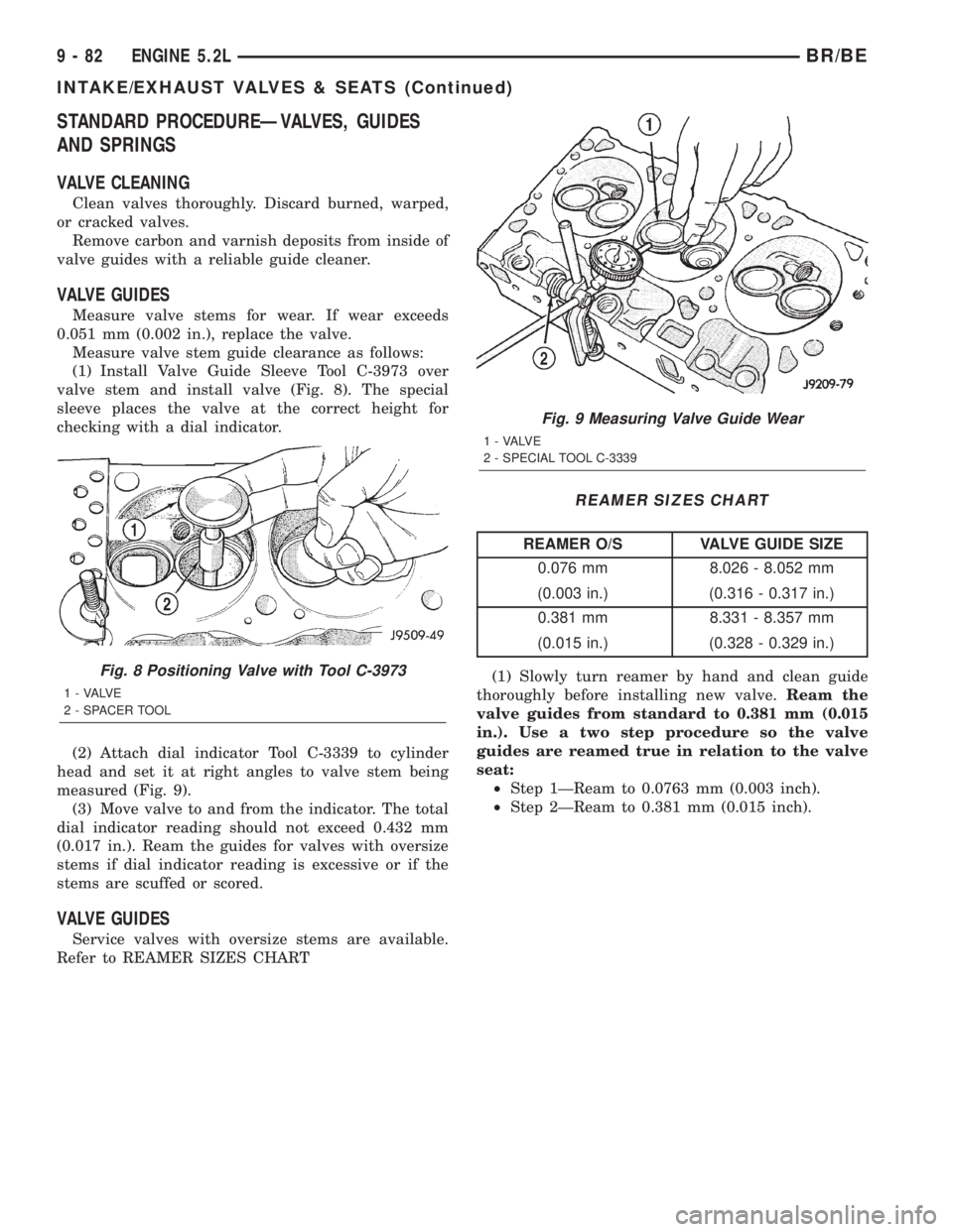
(1) Install Valve Guide Sleeve Tool C-3973 over
valve stem and install valve (Fig. 8). The special
sleeve places the valve at the correct height for
checking with a dial indicator.
(2) Attach dial indicator Tool C-3339 to cylinder
head and set it at right angles to valve stem being
measured (Fig. 9).
(3) Move valve to and from the indicator. The total
dial indicator reading should not exceed 0.432 mm
(0.017 in.). Ream the guides for valves with oversize
stems if dial indicator reading is excessive or if the
stems are scuffed or scored.
VALVE GUIDES
Service valves with oversize stems are available.
Refer to REAMER SIZES CHART
REAMER SIZES CHART
REAMER O/S VALVE GUIDE SIZE
0.076 mm 8.026 - 8.052 mm
(0.003 in.) (0.316 - 0.317 in.)
0.381 mm 8.331 - 8.357 mm
(0.015 in.) (0.328 - 0.329 in.)
(1) Slowly turn reamer by hand and clean guide
thoroughly before installing new valve.Ream the
valve guides from standard to 0.381 mm (0.015
in.). Use a two step procedure so the valve
guides are reamed true in relation to the valve
seat:
²Step 1ÐReam to 0.0763 mm (0.003 inch).
²Step 2ÐReam to 0.381 mm (0.015 inch).
Fig. 8 Positioning Valve with Tool C-3973
1 - VALVE
2 - SPACER TOOL
Fig. 9 Measuring Valve Guide Wear
1 - VALVE
2 - SPECIAL TOOL C-3339
9 - 82 ENGINE 5.2LBR/BE
INTAKE/EXHAUST VALVES & SEATS (Continued)
Page 1251 of 2889
DIAGNOSIS AND TESTINGÐENGINE OIL
LEAKS
Begin with a through visual inspection of the
engine, particularly at the area of the suspected leak.
If an oil leak source is not readily identifiable, the
following steps should be followed:
(1) Do not clean or degrease the engine at this
time because some solvents may cause rubber to
swell, temporarily stopping the leak.
(2) Add an oil-soluble dye (use as recommended by
manufacturer). Start the engine and let idle for
approximately 15 minutes. Check the oil dipstick to
be sure the dye is thoroughly mixed as indicated
with a bright yellow color under a black light source.
(3) Using a black light, inspect the entire engine
for fluorescent dye, particularly at the suspected area
of oil leak. If the oil leak is found and identified,
repair per service manual instructions.
(4) If dye is not observed, drive the vehicle at var-
ious speeds for approximately 24km (15 miles), and
repeat previous step.
(5) If the oil leak source is not positively identified
at this time, proceed with the air leak detection test
method as follows:
(6) Disconnect the breather cap to air cleaner hose
at the breather cap end. Cap or plug breather cap
nipple.
(7) Remove the PCV valve from the cylinder head
cover. Cap or plug the PCV valve grommet.
(8) Attach an air hose with pressure gauge and
regulator to the dipstick tube.
CAUTION: Do not subject the engine assembly to
more than 20.6 kpa (3 PSI) of test pressure.
(9) Gradually apply air pressure from 1 psi to 2.5
psi maximum while applying soapy water at the sus-
pected source. Adjust the regulator to the suitable
test pressure that provide the best bubbles which
will pinpoint the leak source. If the oil leak is
detected and identified, repair per service manual
procedures.
(10) If the leakage occurs at the rear oil seal area,
refer to the section, Inspection for Rear Seal Area
Leak.
(11) If no leaks are detected, turn off the air sup-
ply and remove the air hose and all plugs and caps.
Install the PCV valve and breather cap hose. Proceed
to next step.
(12) Clean the oil off the suspect oil leak area
using a suitable solvent. Drive the vehicle at various
speeds approximately 24 km (15 miles). Inspect the
engine for signs of an oil leak by using a black light.
DIAGNOSIS AND TESTINGÐENGINE OIL
PRESSURE
(1) Remove oil pressure sending unit.
(2) Install Oil Pressure Line and Gauge Tool
C-3292. Start engine and record pressure. (Refer to 9
- ENGINE - SPECIFICATIONS).
OIL
STANDARD PROCEDUREÐENGINE OIL
OIL LEVEL INDICATOR (DIPSTICK)
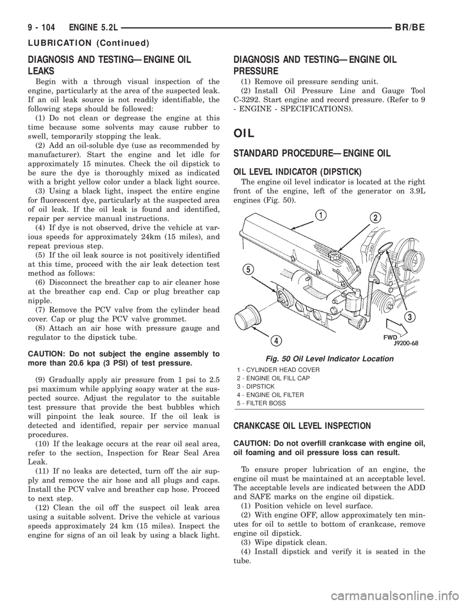
The engine oil level indicator is located at the right
front of the engine, left of the generator on 3.9L
engines (Fig. 50).
CRANKCASE OIL LEVEL INSPECTION
CAUTION: Do not overfill crankcase with engine oil,
oil foaming and oil pressure loss can result.
To ensure proper lubrication of an engine, the
engine oil must be maintained at an acceptable level.
The acceptable levels are indicated between the ADD
and SAFE marks on the engine oil dipstick.
(1) Position vehicle on level surface.
(2) With engine OFF, allow approximately ten min-
utes for oil to settle to bottom of crankcase, remove
engine oil dipstick.
(3) Wipe dipstick clean.
(4) Install dipstick and verify it is seated in the
tube.
Fig. 50 Oil Level Indicator Location
1 - CYLINDER HEAD COVER
2 - ENGINE OIL FILL CAP
3 - DIPSTICK
4 - ENGINE OIL FILTER
5 - FILTER BOSS
9 - 104 ENGINE 5.2LBR/BE
LUBRICATION (Continued)
Page 1286 of 2889
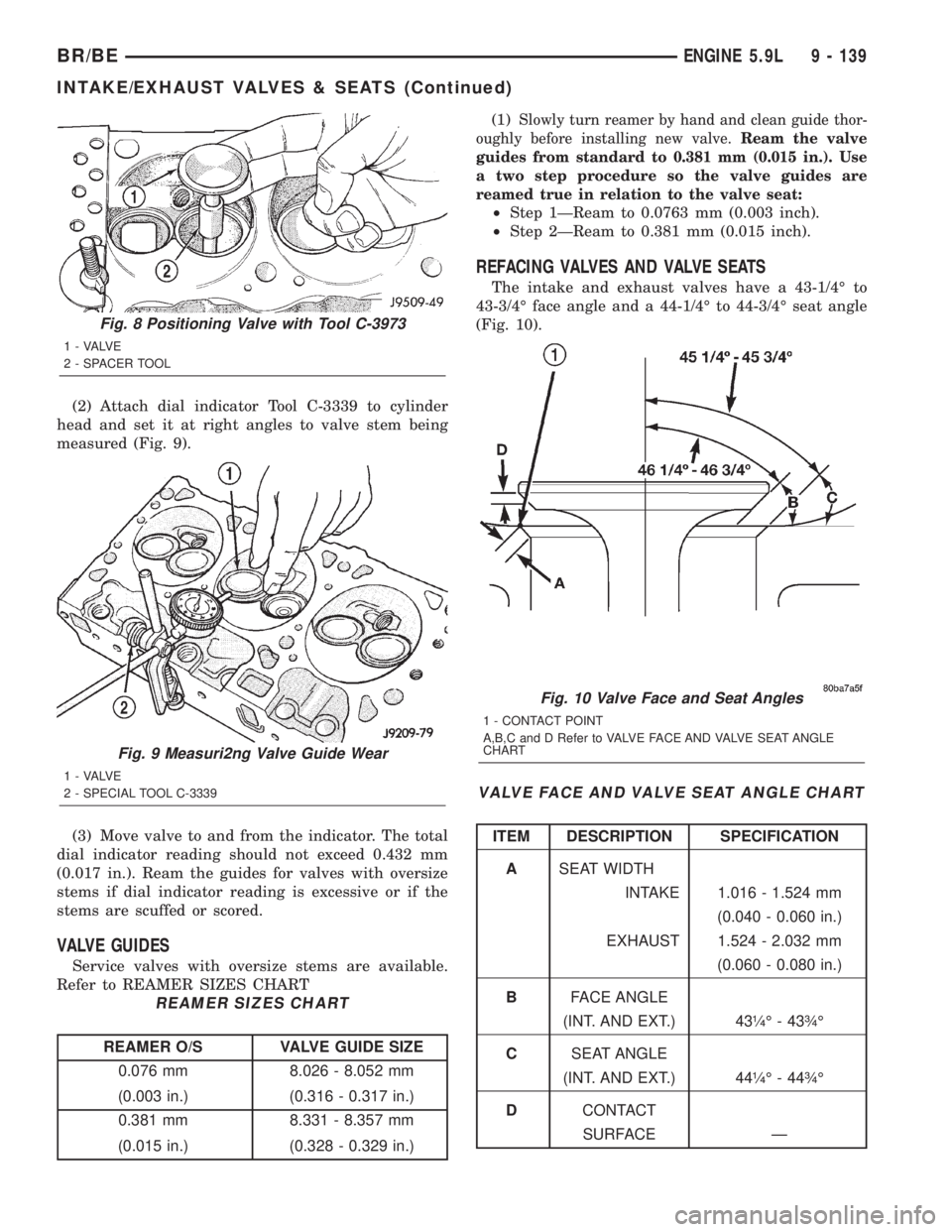
(2) Attach dial indicator Tool C-3339 to cylinder
head and set it at right angles to valve stem being
measured (Fig. 9).
(3) Move valve to and from the indicator. The total
dial indicator reading should not exceed 0.432 mm
(0.017 in.). Ream the guides for valves with oversize
stems if dial indicator reading is excessive or if the
stems are scuffed or scored.
VALVE GUIDES
Service valves with oversize stems are available.
Refer to REAMER SIZES CHART
REAMER SIZES CHART
REAMER O/S VALVE GUIDE SIZE
0.076 mm 8.026 - 8.052 mm
(0.003 in.) (0.316 - 0.317 in.)
0.381 mm 8.331 - 8.357 mm
(0.015 in.) (0.328 - 0.329 in.)(1)
Slowly turn reamer by hand and clean guide thor-
oughly before installing new valve.Ream the valve
guides from standard to 0.381 mm (0.015 in.). Use
a two step procedure so the valve guides are
reamed true in relation to the valve seat:
²Step 1ÐReam to 0.0763 mm (0.003 inch).
²Step 2ÐReam to 0.381 mm (0.015 inch).
REFACING VALVES AND VALVE SEATS
The intake and exhaust valves have a 43-1/4É to
43-3/4É face angle and a 44-1/4É to 44-3/4É seat angle
(Fig. 10).
VALVE FACE AND VALVE SEAT ANGLE CHART
ITEM DESCRIPTION SPECIFICATION
ASEAT WIDTH
INTAKE 1.016 - 1.524 mm
(0.040 - 0.060 in.)
EXHAUST 1.524 - 2.032 mm
(0.060 - 0.080 in.)
BFACE ANGLE
(INT. AND EXT.) 43òÉ - 43ôÉ
CSEAT ANGLE
(INT. AND EXT.) 44òÉ - 44ôÉ
DCONTACT
SURFACE Ð
Fig. 8 Positioning Valve with Tool C-3973
1 - VALVE
2 - SPACER TOOL
Fig. 9 Measuri2ng Valve Guide Wear
1 - VALVE
2 - SPECIAL TOOL C-3339
Fig. 10 Valve Face and Seat Angles
1 - CONTACT POINT
A,B,C and D Refer to VALVE FACE AND VALVE SEAT ANGLE
CHART
BR/BEENGINE 5.9L 9 - 139
INTAKE/EXHAUST VALVES & SEATS (Continued)
Page 1307 of 2889
DIAGNOSIS AND TESTINGÐENGINE OIL
LEAKS
Begin with a through visual inspection of the
engine, particularly at the area of the suspected leak.
If an oil leak source is not readily identifiable, the
following steps should be followed:
(1) Do not clean or degrease the engine at this
time because some solvents may cause rubber to
swell, temporarily stopping the leak.
(2) Add an oil-soluble dye (use as recommended by
manufacturer). Start the engine and let idle for
approximately 15 minutes. Check the oil dipstick to
be sure the dye is thoroughly mixed as indicated
with a bright yellow color under a black light source.
(3) Using a black light, inspect the entire engine
for fluorescent dye, particularly at the suspected area
of oil leak. If the oil leak is found and identified,
repair per service manual instructions.
(4) If dye is not observed, drive the vehicle at var-
ious speeds for approximately 24km (15 miles), and
repeat previous step.
(5) If the oil leak source is not positively identified
at this time, proceed with the air leak detection test
method as follows:
(6) Disconnect the breather cap to air cleaner hose
at the breather cap end. Cap or plug breather cap
nipple.
(7) Remove the PCV valve from the cylinder head
cover. Cap or plug the PCV valve grommet.
(8) Attach an air hose with pressure gauge and
regulator to the dipstick tube.
CAUTION: Do not subject the engine assembly to
more than 20.6 kpa (3 PSI) of test pressure.
(9) Gradually apply air pressure from 1 psi to 2.5
psi maximum while applying soapy water at the sus-
pected source. Adjust the regulator to the suitable
test pressure that provide the best bubbles which
will pinpoint the leak source. If the oil leak is
detected and identified, repair per service manual
procedures.
(10) If the leakage occurs at the rear oil seal area,
refer to the section, Inspection for Rear Seal Area
Leak.
(11) If no leaks are detected, turn off the air sup-
ply and remove the air hose and all plugs and caps.
Install the PCV valve and breather cap hose. Proceed
to next step.
(12) Clean the oil off the suspect oil leak area
using a suitable solvent. Drive the vehicle at various
speeds approximately 24 km (15 miles). Inspect the
engine for signs of an oil leak by using a black light.
DIAGNOSIS AND TESTINGÐENGINE OIL
PRESSURE
(1) Remove oil pressure sending unit.
(2) Install Oil Pressure Line and Gauge Tool
C-3292. Start engine and record pressure. (Refer to 9
- ENGINE - SPECIFICATIONS).
OIL
STANDARD PROCEDUREÐENGINE OIL
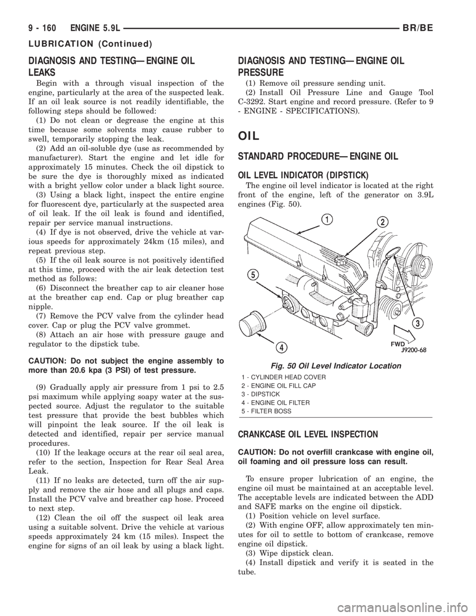
OIL LEVEL INDICATOR (DIPSTICK)
The engine oil level indicator is located at the right
front of the engine, left of the generator on 3.9L
engines (Fig. 50).
CRANKCASE OIL LEVEL INSPECTION
CAUTION: Do not overfill crankcase with engine oil,
oil foaming and oil pressure loss can result.
To ensure proper lubrication of an engine, the
engine oil must be maintained at an acceptable level.
The acceptable levels are indicated between the ADD
and SAFE marks on the engine oil dipstick.
(1) Position vehicle on level surface.
(2) With engine OFF, allow approximately ten min-
utes for oil to settle to bottom of crankcase, remove
engine oil dipstick.
(3) Wipe dipstick clean.
(4) Install dipstick and verify it is seated in the
tube.
Fig. 50 Oil Level Indicator Location
1 - CYLINDER HEAD COVER
2 - ENGINE OIL FILL CAP
3 - DIPSTICK
4 - ENGINE OIL FILTER
5 - FILTER BOSS
9 - 160 ENGINE 5.9LBR/BE
LUBRICATION (Continued)
Page 1342 of 2889
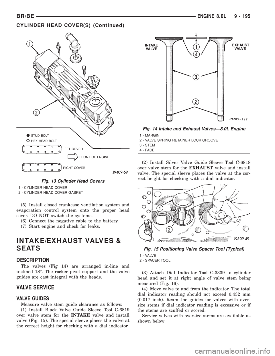
(5) Install closed crankcase ventilation system and
evaporation control system onto the proper head
cover. DO NOT switch the systems.
(6) Connect the negative cable to the battery.
(7) Start engine and check for leaks.
INTAKE/EXHAUST VALVES &
SEATS
DESCRIPTION
The valves (Fig 14) are arranged in-line and
inclined 18É. The rocker pivot support and the valve
guides are cast integral with the heads.
VALVE SERVICE
VALVE GUIDES
Measure valve stem guide clearance as follows:
(1) Install Black Valve Guide Sleeve Tool C-6819
over valve stem for theINTAKEvalve and install
valve (Fig. 15). The special sleeve places the valve at
the correct height for checking with a dial indicator.(2) Install Silver Valve Guide Sleeve Tool C-6818
over valve stem for theEXHAUSTvalve and install
valve. The special sleeve places the valve at the cor-
rect height for checking with a dial indicator.
(3) Attach Dial Indicator Tool C-3339 to cylinder
head and set it at right angle of valve stem being
measured (Fig. 16).
(4) Move valve to and from the indicator. The total
dial indicator reading should not exceed 0.432 mm
(0.017 inch). Ream the guides for valves with over-
size stems if dial indicator reading is excessive or if
the stems are scuffed or scored.
Service valves with oversize stems are available as
shown below
Fig. 13 Cylinder Head Covers
1 - CYLINDER HEAD COVER
2 - CYLINDER HEAD COVER GASKET
Fig. 14 Intake and Exhaust ValvesÐ8.0L Engine
1 - MARGIN
2 - VALVE SPRING RETAINER LOCK GROOVE
3 - STEM
4-FACE
Fig. 15 Positioning Valve Spacer Tool (Typical)
1 - VALVE
2 - SPACER TOOL
BR/BEENGINE 8.0L 9 - 195
CYLINDER HEAD COVER(S) (Continued)
Page 1442 of 2889
DIAGNOSIS AND TESTINGÐENGINE OIL
PRESSURE
(1) Remove the engine oil pressure sensor and
install Oil Pressure Line and Gauge Tool C-3292 with
a suitable adapter.
(2) Start engine and warm to operating tempera-
ture.
(3) Record engine oil pressure and compare with
engine oil pressure chart.
CAUTION: If engine oil pressure is zero at idle, DO
NOT RUN THE ENGINE.
Engine Oil Pressure (MIN)
At Idle 103.4 kPa (15 psi)
At 2000 rpm 310.2 kPa (45 psi)
If minimum engine oil pressure is below these
ranges, (Refer to 9 - ENGINE - DIAGNOSIS AND
TESTING).
(4) Remove oil pressure gauge and install the oil
pressure sensor. Tighten the sensor to 16 N´m (144
in. lbs.) torque.
OIL
STANDARD PROCEDURE-ENGINE OIL LEVEL
CAUTION: Do not overfill crankcase with engine oil,
oil foaming and oil pressure loss can result.
To ensure proper lubrication of an engine, the
engine oil must be maintained at an acceptable level.
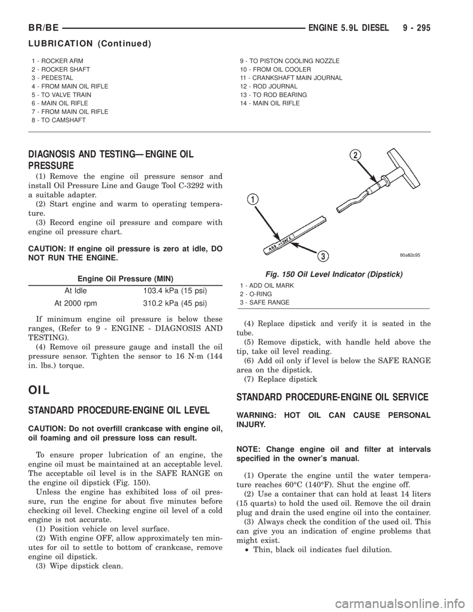
The acceptable oil level is in the SAFE RANGE on
the engine oil dipstick (Fig. 150).
Unless the engine has exhibited loss of oil pres-
sure, run the engine for about five minutes before
checking oil level. Checking engine oil level of a cold
engine is not accurate.
(1) Position vehicle on level surface.
(2) With engine OFF, allow approximately ten min-
utes for oil to settle to bottom of crankcase, remove
engine oil dipstick.
(3) Wipe dipstick clean.(4)
Replace dipstick and verify it is seated in the
tube.
(5) Remove dipstick, with handle held above the
tip, take oil level reading.
(6) Add oil only if level is below the SAFE RANGE
area on the dipstick.
(7) Replace dipstick
STANDARD PROCEDURE-ENGINE OIL SERVICE
WARNING: HOT OIL CAN CAUSE PERSONAL
INJURY.
NOTE: Change engine oil and filter at intervals
specified in the owner's manual.
(1) Operate the engine until the water tempera-
ture reaches 60ÉC (140ÉF). Shut the engine off.
(2) Use a container that can hold at least 14 liters
(15 quarts) to hold the used oil. Remove the oil drain
plug and drain the used engine oil into the container.
(3) Always check the condition of the used oil. This
can give you an indication of engine problems that
might exist.
²Thin, black oil indicates fuel dilution.
1 - ROCKER ARM
2 - ROCKER SHAFT
3 - PEDESTAL
4 - FROM MAIN OIL RIFLE
5 - TO VALVE TRAIN
6 - MAIN OIL RIFLE
7 - FROM MAIN OIL RIFLE
8 - TO CAMSHAFT9 - TO PISTON COOLING NOZZLE
10 - FROM OIL COOLER
11 - CRANKSHAFT MAIN JOURNAL
12 - ROD JOURNAL
13 - TO ROD BEARING
14 - MAIN OIL RIFLE
Fig. 150 Oil Level Indicator (Dipstick)
1 - ADD OIL MARK
2 - O-RING
3 - SAFE RANGE
BR/BEENGINE 5.9L DIESEL 9 - 295
LUBRICATION (Continued)
Page 1471 of 2889
CAUTION: The turbocharger is only serviced as an
assembly. Do not attempt to repair the turbocharger
as turbocharger and/or engine damage can result.
CLEANING
Clean the turbocharger and exhaust manifold
mounting surfaces with a suitable scraper.
INSPECTION
Visually inspect the turbocharger and exhaust
manifold gasket surfaces. Replace stripped or eroded
mounting studs.
(1) Visually inspect the turbocharger for cracks.
The following cracks are NOT acceptable:
²Cracks in the turbine and compressor housing
that go completely through.
²Cracks in the mounting flange that are longer
than 15 mm (0.6 in.).
²Cracks in the mounting flange that intersect
bolt through-holes.
²Two (2) Cracks in the mounting flange that are
closer than 6.4 mm (0.25 in.) together.
(2) Visually inspect the impeller and compressor
wheel fins for nicks, cracks, or chips. Note: Some
impellers may have a factory placed paint mark
which, after normal operation, appears to be a crack.Remove this mark with a suitable solvent to verify
that it is not a crack.
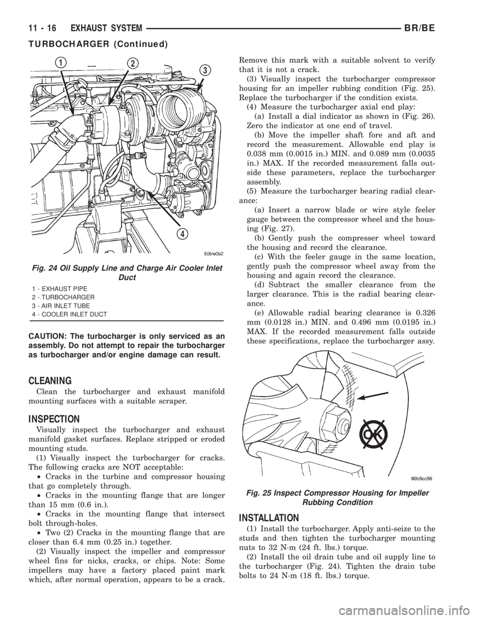
(3) Visually inspect the turbocharger compressor
housing for an impeller rubbing condition (Fig. 25).
Replace the turbocharger if the condition exists.
(4) Measure the turbocharger axial end play:
(a) Install a dial indicator as shown in (Fig. 26).
Zero the indicator at one end of travel.
(b) Move the impeller shaft fore and aft and
record the measurement. Allowable end play is
0.038 mm (0.0015 in.) MIN. and 0.089 mm (0.0035
in.) MAX. If the recorded measurement falls out-
side these parameters, replace the turbocharger
assembly.
(5) Measure the turbocharger bearing radial clear-
ance:
(a) Insert a narrow blade or wire style feeler
gauge between the compressor wheel and the hous-
ing (Fig. 27).
(b) Gently push the compresser wheel toward
the housing and record the clearance.
(c) With the feeler gauge in the same location,
gently push the compressor wheel away from the
housing and again record the clearance.
(d) Subtract the smaller clearance from the
larger clearance. This is the radial bearing clear-
ance.
(e) Allowable radial bearing clearance is 0.326
mm (0.0128 in.) MIN. and 0.496 mm (0.0195 in.)
MAX. If the recorded measurement falls outside
these specifications, replace the turbocharger assy.
INSTALLATION
(1) Install the turbocharger. Apply anti-seize to the
studs and then tighten the turbocharger mounting
nuts to 32 N´m (24 ft. lbs.) torque.
(2) Install the oil drain tube and oil supply line to
the turbocharger (Fig. 24). Tighten the drain tube
bolts to 24 N´m (18 ft. lbs.) torque.
Fig. 24 Oil Supply Line and Charge Air Cooler Inlet
Duct
1 - EXHAUST PIPE
2 - TURBOCHARGER
3 - AIR INLET TUBE
4 - COOLER INLET DUCT
Fig. 25 Inspect Compressor Housing for Impeller
Rubbing Condition
11 - 16 EXHAUST SYSTEMBR/BE
TURBOCHARGER (Continued)
Page 1543 of 2889
²Fuel filter/water separator
²Fuel heater
²Fuel heater relay
²Fuel transfer (lift) pump
²Fuel injection pump
²Fuel injectors
²Fuel heater temperature sensor
²Fuel tank
²Fuel tank filler/vent tube assembly
²Fuel tank filler tube cap
²Fuel tank module containing the rollover valve,
fuel gauge sending unit (fuel level sensor) and a sep-
arate fuel filter located at bottom of tank module
²Fuel tubes/lines/hoses
²High-pressure fuel injector lines
²In-tank fuel filter (at bottom of fuel tank mod-
ule)
²Low-pressure fuel supply lines
²Low-pressure fuel return line
²Overflow valve
²Quick-connect fittings
²Throttle cable
²Water draining
OPERATION
WARNING: HIGH-PRESSURE FUEL LINES DELIVER
DIESEL FUEL UNDER EXTREME PRESSURE FROM
THE INJECTION PUMP TO THE FUEL INJECTORS.
THIS MAY BE AS HIGH AS 120,000 KPA (17,405
PSI). USE EXTREME CAUTION WHEN INSPECTING
FOR HIGH-PRESSURE FUEL LEAKS. INSPECT FOR
HIGH-PRESSURE FUEL LEAKS WITH A SHEET OF
CARDBOARD. HIGH FUEL INJECTION PRESSURE
CAN CAUSE PERSONAL INJURY IF CONTACT IS
MADE WITH THE SKIN.
DIAGNOSIS AND TESTING - AIR IN FUEL
SYSTEM
Air will enter the fuel system whenever fuel supply
lines, separator filters, injection pump, high-pressure
lines or injectors are removed or disconnected. Air
trapped in the fuel system can result in hard start-
ing, a rough running engine, engine misfire, low
power, excessive smoke and fuel knock. After service
is performed, air must be bled from the system
before starting the engine.Inspect the fuel system from the fuel transfer
pump to the injectors for loose connections. Leaking
fuel is an indicator of loose connections or defective
seals. Air can also enter the fuel system between the
fuel tank and the transfer pump. Inspect the fuel
tank and fuel lines for damage that might allow air
into the system.
For air bleeding, refer to the Air Bleed Procedure.
DIAGNOSIS AND TESTING - FUEL SUPPLY
RESTRICTIONS
LOW-PRESSURE LINES
Fuel supply line restrictions or a defective fuel
transfer pump can cause starting problems and pre-
vent engine from accelerating. The starting problems
include; low power and/or white fog like exhaust.
Test all fuel supply lines for restrictions or block-
age. Flush or replace as necessary. Bleed fuel system
of air once a fuel supply line has been replaced. Refer
to Air Bleed Procedure for procedures.
To test for fuel line restrictions, a vacuum restric-
tion test may be performed. Refer to Fuel Transfer
Pump Pressure Test.
HIGH-PRESSURE LINES
Restricted (kinked or bent) high-pressure lines can
cause starting problems, poor engine performance,
engine mis-fire and white smoke from exhaust.
Examine all high-pressure lines for any damage.
Each radius on each high-pressure line must be
smooth and free of any bends or kinks.
Replace damaged, restricted or leaking high-pres-
sure fuel lines with correct replacement line.
CAUTION: All high-pressure fuel lines must be
clamped securely in place in holders. Lines cannot
contact each other or other components. Do not
attempt to weld high-pressure fuel lines or to repair
lines that are damaged. If line is kinked or bent, it
must be replaced. Use only recommended lines
when replacement of high-pressure fuel line is nec-
essary.
STANDARD PROCEDURES - WATER DRAINING
AT FUEL FILTER
Refer to Fuel Filter/Water Separator removal/in-
stallation for procedures.
14 - 56 FUEL DELIVERY - DIESELBR/BE
FUEL DELIVERY - DIESEL (Continued)