2001 DODGE RAM sensor
[x] Cancel search: sensorPage 594 of 2889
behind the cutout causes the ªWAIT TO STARTº text
to appear in red through the translucent outer layer
of the overlay when the indicator is illuminated from
behind by a Light Emitting Diode (LED) that is sol-
dered onto the instrument cluster electronic circuit
board. The wait-to-start indicator is serviced as a
unit with the instrument cluster.
OPERATION
The wait-to-start indicator gives an indication to
the vehicle operator when the diesel engine intake
air heater is energized in its preheat operating mode.
This indicator is controlled by a hard wired input to
the instrument cluster from the Engine Control Mod-
ule (ECM). The wait-to-start indicator Light Emitting
Diode (LED) receives battery current on the instru-
ment cluster electronic circuit board through the
fused ignition switch output (st-run) circuit whenever
the ignition switch is in the On or Start positions;
therefore, the lamp will always be off when the igni-
tion switch is in any position except On or Start. The
indicator LED only illuminates when it is switched to
ground by the input from the ECM. The ECM will
turn on the wait-to-start indicator by pulling the
wait-to-start indicator driver circuit to ground each
time the ignition switch is turned to the On or Start
positions. The indicator then remains illuminated
until the ECM detects that the air within the intake
manifold is the proper temperature to ensure reliable
and efficient engine starting, until the ECM detects
that the engine is running, or until the ignition
switch is turned to the Off position, whichever occurs
first.
The ECM continually monitors the intake manifold
air temperature sensor, the Manifold Absolute Pres-
sure (MAP) sensor, and many other vehicle condi-
tions to determine when the wait-to-start indicator
should be illuminated. For proper diagnosis of the
wait-to-start indicator, the ECM, or the inputs the
ECM uses to control the wait-to-start indicator oper-
ation, a DRBIIItscan tool is required. Refer to the
appropriate diagnostic information.
WASHER FLUID INDICATOR
DESCRIPTION
A washer fluid indicator is standard equipment on
all instrument clusters. The washer fluid indicator is
located near the lower edge of the instrument cluster
overlay, to the right of center. The washer fluid indi-
cator consists of a stenciled cutout of the words
ªLOW WASHERº in the opaque layer of the instru-
ment cluster overlay. The dark outer layer of the
overlay prevents the indicator from being clearly vis-
ible when it is not illuminated. An amber lens behindthe cutout in the opaque layer of the overlay causes
the ªLOW WASHERº text to appear in amber
through the translucent outer layer of the overlay
when it is illuminated from behind by a Light Emit-
ting Diode (LED) soldered onto the instrument clus-
ter electronic circuit board. The washer fluid
indicator is serviced as a unit with the instrument
cluster.
OPERATION
The washer fluid indicator gives an indication to
the vehicle operator when the fluid level in the
washer fluid reservoir is low. This indicator is con-
trolled by a transistor on the instrument cluster elec-
tronic circuit board based upon cluster programming
and a hard wired washer fluid level switch input to
the cluster. The washer fluid indicator Light Emit-
ting Diode (LED) receives battery current on the
instrument cluster electronic circuit board through
the fused ignition switch output (st-run) circuit
whenever the ignition switch is in the On or Start
positions; therefore, the indicator will always be off
when the ignition switch is in any position except On
or Start. The LED only illuminates when it is pro-
vided a path to ground by the instrument cluster
transistor. The instrument cluster will turn on the
washer fluid indicator for the following reasons:
²Bulb Test- Each time the ignition switch is
turned to the On position the indicator is illuminated
for about two seconds as a bulb test.
²Washer Fluid Level Switch Input- Immedi-
ately after the bulb test, if the cluster senses ground
on the washer fluid switch sense circuit for more
than about thirty seconds, it turns on the washer
fluid indicator. Any time after the bulb test, the clus-
ter must sense ground on the washer fluid switch
sense circuit for more than about sixty seconds before
it turns on the indicator. Once illuminated, the indi-
cator will remain illuminated until the ignition
switch is cycled and the cluster senses an open cir-
cuit on the low washer fluid sense input. This strat-
egy is intended to reduce the effect that fluid
sloshing within the washer reservoir can have on
reliable indicator operation.
²Actuator Test- Each time the cluster is put
through the actuator test, the indicator will be
turned on during the bulb check portion of the test to
confirm the functionality of the LED and the cluster
control circuitry.
The washer fluid level switch is connected in series
between ground and the washer fluid switch sense
input to the instrument cluster. For more informa-
tion on the washer fluid level switch,(Refer to 8 -
ELECTRICAL/WIPERS/WASHERS/WASHER FLUID
LEVEL SWITCH - OPERATION). For further diag-
nosis of the washer fluid indicator or the instrument
BR/BEINSTRUMENT CLUSTER 8J - 35
WAIT-TO-START INDICATOR (Continued)
Page 596 of 2889
OPERATION
The water-in-fuel indicator gives an indication to
the vehicle operator when the water accumulated in
the diesel engine fuel filter/separator filter bowl
requires draining. This indicator is controlled by a
transistor on the instrument cluster circuit board
based upon cluster programming and electronic mes-
sages received by the cluster from the Engine Control
Module (ECM) over the Chrysler Collision Detection
(CCD) data bus. The water-in-fuel indicator Light
Emitting Diode (LED) receives battery current on the
instrument cluster electronic circuit board through
the fused ignition switch output (st-run) circuit
whenever the ignition switch is in the On or Start
positions; therefore, the indicator will always be off
when the ignition switch is in any position except On
or Start. The LED only illuminates when it is
switched to ground by the instrument cluster transis-
tor. The instrument cluster will turn on the water-in-
fuel indicator for the following reasons:
²Bulb Test- Each time the ignition switch is
turned to the On position the indicator is illuminated
for about two seconds as a bulb test.
²Water-In-Fuel Lamp-On Message- Each time
the cluster receives a water-in-fuel lamp-on messagefrom the ECM, the indicator will be illuminated. The
indicator remains illuminated until the cluster
receives a water-in-fuel lamp-off message from the
ECM or until the ignition switch is turned to the Off
position, whichever occurs first.
²Actuator Test- Each time the cluster is put
through the actuator test, the indicator will be
turned on during the bulb check portion of the test to
confirm the functionality of the LED and the cluster
control circuitry.
The ECM continually monitors the water-in-fuel
sensor, then sends the proper messages to the instru-
ment cluster. For further diagnosis of the water-in-
fuel indicator or the instrument cluster circuitry that
controls the indicator, (Refer to 8 - ELECTRICAL/IN-
STRUMENT CLUSTER - DIAGNOSIS AND TEST-
ING). For proper diagnosis of the water-in-fuel
sensor, the ECM, the CCD data bus, or the message
inputs to the instrument cluster that control the
water-in-fuel indicator, a DRBIIItscan tool is
required. Refer to the appropriate diagnostic
information.
BR/BEINSTRUMENT CLUSTER 8J - 37
WATER-IN-FUEL INDICATOR (Continued)
Page 601 of 2889
(9) Disconnect the instrument panel wire harness
connector for the multi-function switch from the
switch connector receptacle. Check for continuity
between the hazard flasher signal circuit cavities in
the JB receptacle for the combination flasher and the
instrument panel wire harness connector for the
multi-function switch. There should be continuity. If
OK, go to Step 10. If not OK, repair the open hazard
flasher signal circuit between the JB and the multi-
function switch as required.
(10) Check for continuity between the flasher out-
put circuit cavities of the JB receptacle for the com-
bination flasher and in the instrument panel wire
harness connector for the multi-function switch.
There should be continuity. If OK, test the multi-
function switch. (Refer to 8 - ELECTRICAL/LAMPS/
LIGHTING - EXTERIOR/MULTI-FUNCTION
SWITCH - DIAGNOSIS AND TESTING). If not OK,
repair the open flasher output circuit between the JB
and the multi-function switch as required.
SPECIFICATIONS
EXTERIOR LAMPS
LAMP BULB
Back-up 3157
Cargo 921
Center High Mounted
Stop921
Clearance Roof Mounted 168
Fog Lamps 896
Headlamp - SLT 9004LL
Headlamp - Sport Low
Beam9007
Headlamp - Sport High
Beam9004LL
License Plate w/o
Bumper1155
License Plate -Step
Bumper168
Park/Turn Signal 3157NA
Snow Plow Control 161
Tail/Brake/Turn Signal 3157
Tail/Brake/Cab - Chassis 1157
Underhood 105
SPECIAL TOOLS
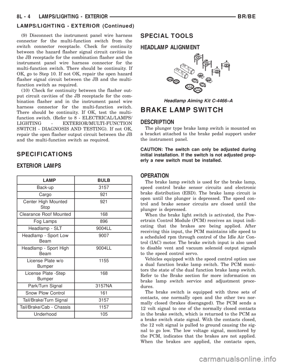
HEADLAMP ALIGNMENT
BRAKE LAMP SWITCH
DESCRIPTION
The plunger type brake lamp switch is mounted on
a bracket attached to the brake pedal support under
the instrument panel.
CAUTION: The switch can only be adjusted during
initial installation. If the switch is not adjusted prop-
erly a new switch must be installed.
OPERATION
The brake lamp switch is used for the brake lamp,
speed control brake sensor circuits and electronic
brake distribution (EBD). The brake lamp circuit is
open until the plunger is depressed. The speed con-
trol and brake sensor circuits are closed until the
plunger is depressed.
When the brake light switch is activated, the Pow-
ertrain Control Module (PCM) receives an input indi-
cating that the brakes are being applied. After
receiving this input, the PCM maintains idle speed to
a scheduled rpm through control of the Idle Air Con-
trol (IAC) motor. The brake switch input is also used
to disable vent and vacuum solenoid output signals
to the speed control servo.
Vehicles equipped with the speed control option use
a dual function brake lamp switch. The PCM moni-
tors the state of the dual function brake lamp switch.
Refer to the Brake section for more information on
brake lamp switch service and adjustment proce-
dures.
The brake switch is equipped with three sets of
contacts, one normally open and the other two nor-
mally closed (brakes disengaged). The PCM sends a
12 volt signal to one of the normally closed contacts
in the brake switch, which is returned to the PCM as
a brake switch state signal. With the contacts closed,
the 12 volt signal is pulled to ground causing the sig-
nal to go low. The low voltage signal, monitored by
the PCM, indicates that the brakes are not applied.
When the brakes are applied, the contacts open,
Headlamp Aiming Kit C-4466±A
8L - 4 LAMPS/LIGHTING - EXTERIORBR/BE
LAMPS/LIGHTING - EXTERIOR (Continued)
Page 606 of 2889
DAYTIME RUNNING LAMP
MODULE
DESCRIPTION
The Daytime Running Lights (Headlamps) System
is installed on vehicles manufactured for sale in Can-
ada only. A separate module, mounted on the cowl,
controls the DRL.
OPERATION
The headlamps are illuminated when the ignition
switch is turned to the ON position. The DRL module
receives a vehicle-moving signal from the vehicle
speed sensor. This provides a constanthead-
lamps-oncondition as long as the vehicle is moving.
The lamps are illuminated at less than 50 percent of
normal intensity.
REMOVAL
(1) Disconnect and isolate the battery negative
cable.
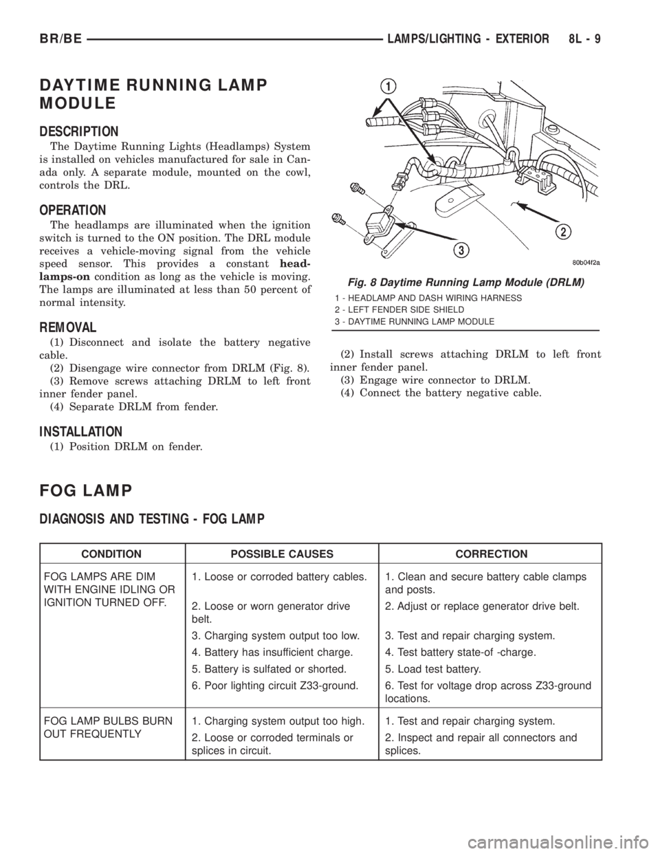
(2) Disengage wire connector from DRLM (Fig. 8).
(3) Remove screws attaching DRLM to left front
inner fender panel.
(4) Separate DRLM from fender.
INSTALLATION
(1) Position DRLM on fender.(2) Install screws attaching DRLM to left front
inner fender panel.
(3) Engage wire connector to DRLM.
(4) Connect the battery negative cable.
FOG LAMP
DIAGNOSIS AND TESTING - FOG LAMP
CONDITION POSSIBLE CAUSES CORRECTION
FOG LAMPS ARE DIM
WITH ENGINE IDLING OR
IGNITION TURNED OFF.1. Loose or corroded battery cables. 1. Clean and secure battery cable clamps
and posts.
2. Loose or worn generator drive
belt.2. Adjust or replace generator drive belt.
3. Charging system output too low. 3. Test and repair charging system.
4. Battery has insufficient charge. 4. Test battery state-of -charge.
5. Battery is sulfated or shorted. 5. Load test battery.
6. Poor lighting circuit Z33-ground. 6. Test for voltage drop across Z33-ground
locations.
FOG LAMP BULBS BURN
OUT FREQUENTLY1. Charging system output too high. 1. Test and repair charging system.
2. Loose or corroded terminals or
splices in circuit.2. Inspect and repair all connectors and
splices.
Fig. 8 Daytime Running Lamp Module (DRLM)
1 - HEADLAMP AND DASH WIRING HARNESS
2 - LEFT FENDER SIDE SHIELD
3 - DAYTIME RUNNING LAMP MODULE
BR/BELAMPS/LIGHTING - EXTERIOR 8L - 9
Page 636 of 2889
MESSAGE SYSTEMS
TABLE OF CONTENTS
page page
OVERHEAD CONSOLE
DESCRIPTION............................1
STANDARD PROCEDURE...................4
COMPASS CALIBRATION..................4
COMPASS VARIATION ADJUSTMENT........4
COMPASS DEMAGNETIZING...............5
REMOVAL...............................6
DISASSEMBLY............................7
ASSEMBLY..............................7
INSTALLATION............................8
SPECIAL TOOLS..........................8
COMPASS/MINI-TRIP COMPUTER
DESCRIPTION............................8OPERATION.............................9
DIAGNOSIS AND TESTING.................10
COMPASS MINI-TRIP COMPUTER..........10
REMOVAL..............................11
INSTALLATION...........................11
AMBIENT TEMP SENSOR
DESCRIPTION...........................11
OPERATION.............................11
DIAGNOSIS AND TESTING.................12
AMBIENT TEMPERATURE SENSOR........12
REMOVAL..............................12
INSTALLATION...........................13
OVERHEAD CONSOLE
DESCRIPTION
Two different overhead console units are available
factory-installed options on this model, base or pre-
mium. The base overhead console unit features a
garage door opener storage bin, a sunglasses storage
bin and two reading and courtesy lamps. The pre-
mium overhead console has all of the features of the
base unit, but adds a compass mini-trip computer.
See the owner's manual in the vehicle glove box for
more information on the features, use and operation
of all of the overhead console components and sys-
tems. Refer toOverhead Consolein the Contents of
Wiring Diagrams for complete circuit diagrams.
The premium overhead console (Fig. 1) includes
two front-mounted reading and courtesy lamps, a
garage door opener storage bin, and a sunglasses
storage bin. The premium overhead console includes
a compass mini-trip computer. The base overhead
console uses the same overhead console housing, but
has a computer cover plug installed in place of the
compass mini-trip computer display module lens and
push buttons.
The rear of the overhead console is secured to two
rear mounting holes in the inner roof panel by two
plastic hook formations that are integral to the over-
head console housing. The front of the overhead con-
sole is secured to the two front mounting holes of the
inner roof panel by two plastic latches that are inte-
gral to the overhead console housing. A single electri-
cal connection joins the overhead console wireharness to the roof wire harness for both the base
and premium overhead console units.
Following are general descriptions of the major
components used in the overhead console. See the
owner's manual in the vehicle glove box for more
information on the use and operation of the various
overhead console features.
GARAGE DOOR OPENER STORAGE BIN
A compartment near the front of the overhead con-
sole is designed to hold most garage door opener
remote control transmitters. The transmitter is
mounted within the compartment with an adhesive-
backed hook and loop fastener patch and, when the
compartment is closed, a push button in the center of
the compartment door is depressed to actuate the
transmitter.
A transmitter mounting kit including the adhesive-
backed hook and loop fastener material is available
for service. The garage door opener storage bin door
and the push button with three assorted length
adapter pegs are also available for service replace-
ment.
The garage door opener storage compartment door
is opened by pressing the integral latch towards the
front of the vehicle. When the compartment door is
opened, the push button unit is removed from the
compartment by squeezing the latch tabs and pulling
the unit downward. With the push button removed,
the garage door opener can be installed in the com-
partment using the adhesive-backed hook and loop
fastener material provided.
BR/BEMESSAGE SYSTEMS 8M - 1
Page 638 of 2889
With the transmitter mounted in the storage bin,
adapter pegs located on the garage door opener push
button unit are selected and mounted on one of two
posts on the back side of the push button. The com-
bination of the adapter peg length and the push but-
ton post location must be suitable to depress the
button of the transmitter when the push button in
the center of the garage door opener storage bin door
is depressed. When the proper combination has been
selected, the push button is reinstalled in the com-
partment and the compartment door is closed.
SUNGLASS STORAGE BIN
A sunglasses storage bin is included in the over-
head console. The storage bin is located near the rear
of the overhead console and is held in the closed posi-
tion by a latch that is integral to the storage bin
door. The interior of the bin is lined with a foam rub-
ber padding material to protect the sunglasses from
being scratched. Dampening springs that are located
on the back of the overhead console reading and
courtesy lamp housing contact the hinges of the sun-
glasses storage bin for a smooth opening action.
The sunglasses storage bin and door unit is avail-
able for service replacement. The hinge dampening
springs are serviced as a unit with the overhead con-
sole reading and courtesy lamp housing.
The sunglasses storage bin is opened by pressing
the latch on the rear edge of the door towards the
front of the vehicle, then pulling the bin downward to
the open position. The integral latch on the sun-
glasses bin door will automatically engage when the
bin is closed. See the owner's manual in the vehicle
glove box for more information on the use and oper-
ation of the sunglasses storage bin.
COMPASS
While in the compass/temperature mode, the com-
pass will display the direction in which the vehicle is
pointed using the eight major compass headings
(Examples: north is N, northeast is NE), along with
the outside ambient temperature. When the compass
unit is placed in the compass/compass in degreesmode, the compass will display the direction the
vehicle is heading using the eight major compass
headings and in degrees (0 to 359 degrees). North is
0 degrees, East is 90 degrees, South is 180 degrees
and West is 270 degrees. It will not display the head-
ings in minutes or seconds.
The self-calibrating compass unit requires no
adjusting in normal use. The compass unit will com-
pensate for magnetism the body of the vehicle may
acquire during normal use. However, avoid placing
anything magnetic directly on the roof of the vehicle.
Magnetic mounts for an antenna, a repair order hat,
or a funeral procession flag can exceed the compen
sating ability of the compass unit if placed on the
roof panel. If the vehicle roof should become magne-
tized, the demagnetizing and calibration procedures
found in this group may be required to restore proper
compass operation.
THERMOMETER
The thermometer displays the outside ambient
temperature in whole degrees. The temperature dis-
play can be changed from Fahrenheit to Celsius
using the U.S./Metric push button. The displayed
temperature is not an instant reading of conditions,
but an average temperature. It may take the ther-
mometer display several minutes to respond to a
major temperature change, such as driving out of a
heated garage into winter temperatures.
When the ignition switch is turned to the Off posi-
tion, the last displayed temperature reading stays in
the thermometer unit memory. When the ignition
switch is turned to the On position again, the ther-
mometer will display the memory temperature if the
engine coolant temperature is above about 43É C
(109É F). If the engine coolant temperature is below
about 43É C (109É F), the thermometer will display
the actual temperature sensed by the ambient tem-
perature sensor. The thermometer temperature dis-
play update interval varies with the vehicle speed;
therefore, if the temperature reading seems inaccu-
rate, drive the vehicle for at least three minutes
1 - SUNGLASSES STORAGE BIN
2 - GARAGE DOOR OPENER STORAGE BIN DOOR
3 - COMPUTER LENS OR COVER PLUG
4 - HOOK AND LOOP FASTENER
5 - SECURITY INDICATOR LAMP
6 - COMPASS MINI-TRIP COMPUTER MODULE
7 - SCREW (3)
8 - SCREW (4)
9 - BULB HOLDERS
10 - SWITCHES11 - WIRE HARNESS
12 - SPRINGS (2)
13 - READING AND COURTESY LAMP HOUSING
14 - REFLECTORS
15 - OVERHEAD CONSOLE HOUSING
16 - LENSES
17 - BUMPER
18 - GARAGE DOOR OPENER PUSH BUTTON
BR/BEMESSAGE SYSTEMS 8M - 3
OVERHEAD CONSOLE (Continued)
Page 639 of 2889
while maintaining a speed of 48 kilometers-per-hour
(30 miles-per-hour) or higher.
The thermometer function is supported by an
ambient temperature sensor. The sensor is mounted
outside the passenger compartment near the front
and center of the vehicle, and is hard wired to the
module. The ambient temperature sensor is available
as a separate service item.
STANDARD PROCEDURE - COMPASS
CALIBRATION
CAUTION: Do not place any external magnets, such
as magnetic roof mount antennas, in the vicinity of
the compass. Do not use magnetic tools when ser-
vicing the overhead console.
The electronic compass unit features a self-cali-
brating design, which simplifies the calibration pro-
cedure. This feature automatically updates the
compass calibration while the vehicle is being driven.
This allows the compass unit to compensate for small
changes in the residual magnetism that the vehicle
may acquire during normal use. If the compass read-
ings appear to be erratic or out of calibration, per-
form the following calibration procedure. Also, new
service replacement compass mini-trip computer
modules must have their compass calibrated using
this procedure. Do not attempt to calibrate the com-
pass near large metal objects such as other vehicles,
large buildings, or bridges; or, near overhead or
underground power lines.
(1) Start the engine. If the compass/temperature
data is not currently being displayed, momentarily
depress and release the Step push button to step
through the display options until you have reached
the compass/temperature display.
(2) Depress both the U.S./Metric and the Step
push buttons at the same time for more than six sec-
onds, until ªCALº appears in the display, then release
both push buttons. The ªCALº in the display indi-
cates that the compass is in the calibration mode.
(3) Drive the vehicle on a level surface, at least
fifty feet away from large metal objects and power
lines, in all four compass directions, such as driving
around a city block several times or driving in two to
three complete circles at a slow to medium speed.
(4) When the calibration is successfully completed,
ªCALº will disappear from the display and normal
compass mini-trip computer operation will resume.
NOTE: If the ªCALº message remains in the display,
either there is excessive magnetism near the com-
pass, or the unit is faulty. Repeat the calibration
procedure at least one more time.NOTE: If the wrong direction is still indicated in the
compass display, the area selected for calibration
may be too close to a strong magnetic field. Repeat
the calibration procedure in another location.
STANDARD PROCEDURE - COMPASS
VARIATION ADJUSTMENT
Compass variance, also known as magnetic decli-
nation, is the difference in angle between magnetic
north and true geographic north. In some geographic
locations, the difference between magnetic and geo-
graphic north is great enough to cause the compass
to give false readings. If this problem occurs, the
compass variance must be set. There are two meth-
ods that can be used to enter this information into
the compass mini-trip computer module. They are
the zone method and the direct method.
ZONE METHOD
(1) Using the Variance Settings map, find your
geographic location and note the zone number (Fig.
2).
(2) Turn the ignition switch to the On position. If
the compass/temperature data is not currently being
displayed, momentarily depress and release the Step
push button to step through the display options until
you have reached the compass/temperature display.
(3) Depress both the U.S./Metric and the Step
push buttons at the same time and hold them down
for more than 100 milliseconds, but not more than
one second. The compass mini-trip computer will
enter the variation adjustment mode and ªVARº
along with the current variance zone will appear in
the display.
(4) Momentarily depress and release the Step push
button to step through the zone numbers, until the
zone number for your geographic location appears in
the display.
(5) After five seconds, the displayed zone will auto-
matically be set in the compass mini-trip computer
module memory and normal operation will resume.
(6) Confirm that the correct directions are now
indicated by the compass.
DIRECT METHOD
(1) Turn the vehicle so it is headed in either the
north or south direction. The vehicle must be headed
within 45 degrees of north or south for this procedure
to work. The vehicle may be moving or stationary.
(2) Turn the ignition switch to the On position. If
the compass/temperature data is not currently being
displayed, momentarily depress and release the Step
push button to step through the display options until
you have reached the compass/temperature display.
8M - 4 MESSAGE SYSTEMSBR/BE
OVERHEAD CONSOLE (Continued)
Page 644 of 2889
Compass mini-trip computer units for vehicles
equipped with the VTSS include a red Light-Emit-
ting Diode (LED) on their electronic circuit board.
This LED protrudes through the bottom of the lens
on the front of the overhead console unit, and serves
as the security indicator lamp. Refer toSecurity
Indicator Lampin Vehicle Theft/Security Systems
for more information on this feature.
The compass mini-trip computer module contains a
central processing unit and interfaces with other
electronic modules in the vehicle on the Chrysler Col-
lision Detection (CCD) data bus network. The CCD
data bus network allows the sharing of sensor infor-
mation. This helps to reduce wire harness complexity,
reduce internal controller hardware, and reduce com-
ponent sensor current loads. At the same time, this
system provides increased reliability, enhanced diag-
nostics, and allows the addition of many new feature
capabilities.
The compass mini-trip computer provides several
electronic functions and features. Some of the func-
tions and features that the compass mini-trip com-
puter module supports and/or controls, include the
following display options:
²Compass and temperature- provides the out-
side temperature and one of eight compass readings
to indicate the direction the vehicle is facing.
²Compass and compass in degrees- provides
one of eight compass readings to indicate the direc-
tion the vehicle is facing and provides the compass
direction in degrees.
²Trip odometer (ODO)- shows the distance
travelled since the last trip computer reset.
²Average fuel economy (AVG ECO)- shows
the average fuel economy since the last trip computer
reset.
²Instant fuel economy (ECO)- shows the
present fuel economy based upon the current vehicle
distance and fuel used information.
²Distance to empty (DTE)- shows the esti-
mated distance that can be travelled with the fuel
remaining in the fuel tank. This estimated distance
is computed using the average miles-per-gallon from
the last 30 gallons of fuel used.
²Elapsed time (ET)- shows the accumulated
ignition-on time since the last trip computer reset.
²Blank screen- the compass mini-trip VFD is
turned off.
The ambient temperature sensor is hard wired to
the compass mini-trip computer module. Data input
for all other compass mini-trip computer functions,
including VFD dimming level, is received through
CCD data bus messages. The compass mini-trip com-
puter uses its internal programming and all of these
inputs to calculate and display the requested data. If
the data displayed is incorrect, perform the self-diag-nostic tests as described in this group. If these tests
prove inconclusive, the use of a DRBIIItscan tool
and the proper Diagnostic Procedures manual are
recommended for further testing of the compass
mini-trip computer module and the CCD data bus.
The compass mini-trip computer module cannot be
repaired, and is available for service only as a unit. If
faulty or damaged, the complete module must be
replaced.
OPERATION
The compass mini-trip computer only operates with
the ignition switch in the On position. When the igni-
tion switch is turned to the On position, all of the
segments in the compass mini-trip computer VFD
will be turned on for one second, then the display
will return to the last function being displayed before
the ignition was turned to the Off position. With the
ignition switch in the On position, momentarily
depressing and releasing the Step push button switch
will cause the compass-mini-trip computer to change
its mode of operation, and momentarily depressing
and releasing the U.S./Metric push button will cause
the unit to toggle between U.S. and Metric measure-
ments. While in either compass mode, depressing the
U.S./Metric push button for more than ten seconds
will toggle the display between the compass/temper-
ature and the compass/compass in degrees modes.
This compass mini-trip computer features several
functions that can be reset. If both the Step and U.S./
Metric push buttons are depressed at the same time
with the ignition switch in the On position, the trip
computer information that can be reset is reset.
Depressing and releasing the Step and U.S./Metric
push buttons at the same time for more than 100
milliseconds, but not more than one second while in
any display mode (except the compass/temperature
mode) will cause a local reset. A local reset affects
only the function currently displayed. See the Reset
Chart below for more information on this feature.
Performing a local reset while in the compass/tem-
perature mode enters the module into the compass
variance setting mode.
Depressing and releasing the Step and U.S./Metric
push buttons at the same time for more than two
seconds while in any display mode (except the com-
pass/temperature mode) will cause a global reset. A
global reset changes all of the trip computer func-
tions that can be reset.
For more information on the features and control
functions of the compass mini-trip computer, see the
owner's manual in the vehicle glove box.
BR/BEMESSAGE SYSTEMS 8M - 9
COMPASS/MINI-TRIP COMPUTER (Continued)