2001 CHRYSLER VOYAGER air condition
[x] Cancel search: air conditionPage 3881 of 4284
TEST ACTION APPLICABILITY
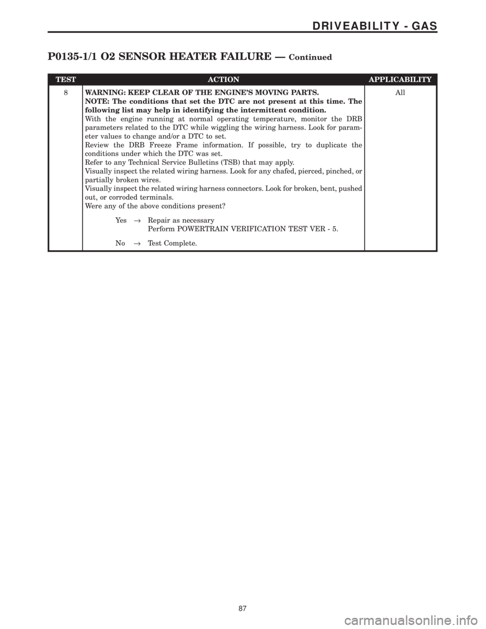
8WARNING: KEEP CLEAR OF THE ENGINE'S MOVING PARTS.
NOTE: The conditions that set the DTC are not present at this time. The
following list may help in identifying the intermittent condition.
With the engine running at normal operating temperature, monitor the DRB
parameters related to the DTC while wiggling the wiring harness. Look for param-
eter values to change and/or a DTC to set.
Review the DRB Freeze Frame information. If possible, try to duplicate the
conditions under which the DTC was set.
Refer to any Technical Service Bulletins (TSB) that may apply.
Visually inspect the related wiring harness. Look for any chafed, pierced, pinched, or
partially broken wires.
Visually inspect the related wiring harness connectors. Look for broken, bent, pushed
out, or corroded terminals.
Were any of the above conditions present?All
Ye s®Repair as necessary
Perform POWERTRAIN VERIFICATION TEST VER - 5.
No®Test Complete.
87
DRIVEABILITY - GAS
P0135-1/1 O2 SENSOR HEATER FAILURE ÐContinued
Page 3883 of 4284

TEST ACTION APPLICABILITY
4 Turn the ignition off.
Disconnect the O2 Sensor harness connector.
Measure the resistance of the O2 Sensor Heater ground circuit in the O2 Sensor
harness connector.
Is the resistance below 5.0 ohms?All
Ye s®Go To 5
No®Repair the O2 Sensor Heater ground circuit for an open.
Perform POWERTRAIN VERIFICATION TEST VER - 5.
5 Turn the ignition off.
Disconnect the O2 Sensor harness connector.
With the DRBIIIt, actuate the O2 Heater Test.
Measure the voltage of the ASD Relay Output circuit in the O2 Sensor harness
connector.
Is the voltage above 11.0 volts?All
Ye s®Go To 6
No®Repair the ASD Relay Output circuit for an open.
Perform POWERTRAIN VERIFICATION TEST VER - 5.
6 If there are no possible causes remaining, view repair. All
Repair
Replace and program the Powertrain Control Module in accor-
dance with the Service Information.
Perform POWERTRAIN VERIFICATION TEST VER - 5.
7WARNING: WHEN THE ENGINE IS OPERATING, DO NOT STAND IN A
DIRECT LINE WITH THE FAN. DO NOT PUT YOUR HANDS NEAR THE
PULLEYS, BELTS OR FAN. DO NOT WEAR LOOSE CLOTHING.
NOTE: The conditions that set the DTC are not present at this time. The
following list may help in identifying the intermittent condition.
With the engine running at normal operating temperature, monitor the DRB
parameters related to the DTC while wiggling the wiring harness. Look for param-
eter values to change and/or a DTC to set.
Review the DRB Freeze Frame information. If possible, try to duplicate the
conditions under which the DTC was set.
Refer to any Technical Service Bulletins (TSB) that may apply.
Visually inspect the related wiring harness. Look for any chafed, pierced, pinched, or
partially broken wires.
Visually inspect the related wiring harness connectors. Look for broken, bent, pushed
out, or corroded terminals.
Were any of the above conditions present?All
Ye s®Repair as necessary
Perform POWERTRAIN VERIFICATION TEST VER - 5.
No®Test Complete.
89
DRIVEABILITY - GAS
P0141-1/2 O2 SENSOR HEATER FAILURE ÐContinued
Page 3886 of 4284
TEST ACTION APPLICABILITY
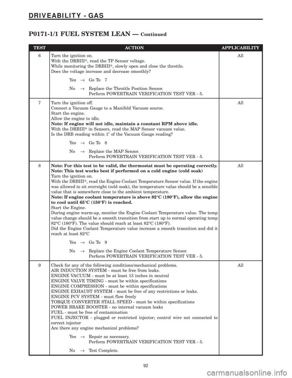
6 Turn the ignition on.
With the DRBIIIt, read the TP Sensor voltage.
While monitoring the DRBIIIt, slowly open and close the throttle.
Does the voltage increase and decrease smoothly?All
Ye s®Go To 7
No®Replace the Throttle Position Sensor.
Perform POWERTRAIN VERIFICATION TEST VER - 5.
7 Turn the ignition off.
Connect a Vacuum Gauge to a Manifold Vacuum source.
Start the engine.
Allow the engine to idle.
Note: If engine will not idle, maintain a constant RPM above idle.
With the DRBIIItin Sensors, read the MAP Sensor vacuum value.
Is the DRB reading within 19of the Vacuum Gauge reading?All
Ye s®Go To 8
No®Replace the MAP Sensor.
Perform POWERTRAIN VERIFICATION TEST VER - 5.
8Note: For this test to be valid, the thermostat must be operating correctly.
Note: This test works best if performed on a cold engine (cold soak)
Turn the ignition on.
With the DRBIIIt, read the Engine Coolant Temperature Sensor value. If the engine
was allowed to sit overnight (cold soak), the temperature value should be a sensible
value that is somewhere close to the ambient temperature.
Note: If engine coolant temperature is above 82ÉC (180ÉF), allow the engine
to cool until 65ÉC (150ÉF) is reached.
Start the Engine.
During engine warm-up, monitor the Engine Coolant Temperature value. The temp
value change should be a smooth transition from start up to normal operating temp
82ÉC (180ÉF). The value should reach at least 82ÉC (180ÉF).
Did the Engine Coolant Temperature value increase a smooth transition and did it
reach at least 82ÉCAll
Ye s®Go To 9
No®Replace the Engine Coolant Temperature Sensor.
Perform POWERTRAIN VERIFICATION TEST VER - 5.
9 Check for any of the following conditions/mechanical problems.
AIR INDUCTION SYSTEM - must be free from leaks.
ENGINE VACUUM - must be at least 13 inches in neutral
ENGINE VALVE TIMING - must be within specifications
ENGINE COMPRESSION - must be within specifications
ENGINE EXHAUST SYSTEM - must be free of any restrictions or leaks.
ENGINE PCV SYSTEM - must flow freely
TORQUE CONVERTER STALL SPEED - must be within specifications
POWER BRAKE BOOSTER - no internal vacuum leaks
FUEL - must be free of contamination
FUEL INJECTOR - plugged or restricted injector; control wire not connected to
correct injector
Are there any engine mechanical problems?All
Ye s®Repair as necessary.
Perform POWERTRAIN VERIFICATION TEST VER - 5.
No®Test Complete.
92
DRIVEABILITY - GAS
P0171-1/1 FUEL SYSTEM LEAN ÐContinued
Page 3888 of 4284
TEST ACTION APPLICABILITY
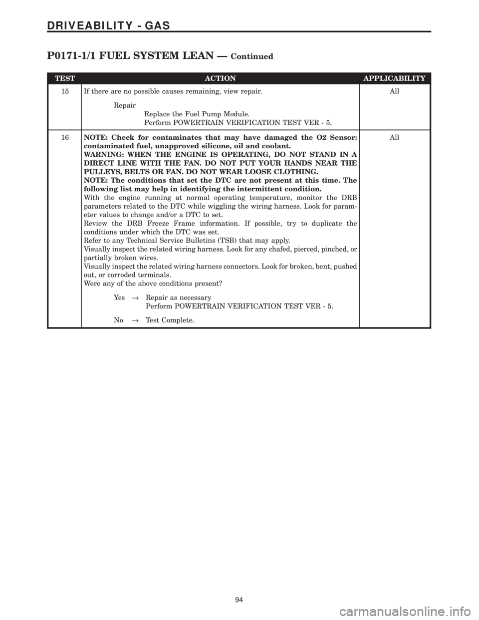
15 If there are no possible causes remaining, view repair. All
Repair
Replace the Fuel Pump Module.
Perform POWERTRAIN VERIFICATION TEST VER - 5.
16NOTE: Check for contaminates that may have damaged the O2 Sensor:
contaminated fuel, unapproved silicone, oil and coolant.
WARNING: WHEN THE ENGINE IS OPERATING, DO NOT STAND IN A
DIRECT LINE WITH THE FAN. DO NOT PUT YOUR HANDS NEAR THE
PULLEYS, BELTS OR FAN. DO NOT WEAR LOOSE CLOTHING.
NOTE: The conditions that set the DTC are not present at this time. The
following list may help in identifying the intermittent condition.
With the engine running at normal operating temperature, monitor the DRB
parameters related to the DTC while wiggling the wiring harness. Look for param-
eter values to change and/or a DTC to set.
Review the DRB Freeze Frame information. If possible, try to duplicate the
conditions under which the DTC was set.
Refer to any Technical Service Bulletins (TSB) that may apply.
Visually inspect the related wiring harness. Look for any chafed, pierced, pinched, or
partially broken wires.
Visually inspect the related wiring harness connectors. Look for broken, bent, pushed
out, or corroded terminals.
Were any of the above conditions present?All
Ye s®Repair as necessary
Perform POWERTRAIN VERIFICATION TEST VER - 5.
No®Test Complete.
94
DRIVEABILITY - GAS
P0171-1/1 FUEL SYSTEM LEAN ÐContinued
Page 3892 of 4284
TEST ACTION APPLICABILITY
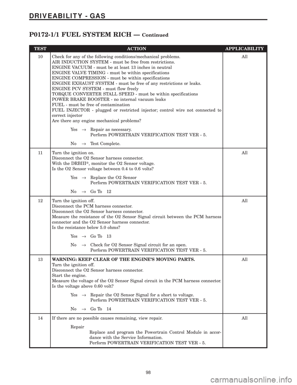
10 Check for any of the following conditions/mechanical problems.
AIR INDUCTION SYSTEM - must be free from restrictions.
ENGINE VACUUM - must be at least 13 inches in neutral
ENGINE VALVE TIMING - must be within specifications
ENGINE COMPRESSION - must be within specifications
ENGINE EXHAUST SYSTEM - must be free of any restrictions or leaks.
ENGINE PCV SYSTEM - must flow freely
TORQUE CONVERTER STALL SPEED - must be within specifications
POWER BRAKE BOOSTER - no internal vacuum leaks
FUEL - must be free of contamination
FUEL INJECTOR - plugged or restricted injector; control wire not connected to
correct injector
Are there any engine mechanical problems?All
Ye s®Repair as necessary.
Perform POWERTRAIN VERIFICATION TEST VER - 5.
No®Test Complete.
11 Turn the ignition on.
Disconnect the O2 Sensor harness connector.
With the DRBIIIt, monitor the O2 Sensor voltage.
Is the O2 Sensor voltage between 0.4 to 0.6 volts?All
Ye s®Replace the O2 Sensor
Perform POWERTRAIN VERIFICATION TEST VER - 5.
No®Go To 12
12 Turn the ignition off.
Disconnect the PCM harness connector.
Disconnect the O2 Sensor harness connector.
Measure the resistance of the O2 Sensor Signal circuit between the PCM harness
connector and the O2 Sensor harness connector.
Is the resistance below 5.0 ohms?All
Ye s®Go To 13
No®Check for O2 Sensor Signal circuit for an open.
Perform POWERTRAIN VERIFICATION TEST VER - 5.
13WARNING: KEEP CLEAR OF THE ENGINE'S MOVING PARTS.
Turn the ignition off.
Disconnect the O2 Sensor harness connector.
Start the engine.
Measure the voltage of the O2 Sensor Signal circuit in the PCM harness connector.
Is the voltage above 0.60 volt?All
Ye s®Repair the O2 Sensor Signal for a short to voltage.
Perform POWERTRAIN VERIFICATION TEST VER - 5.
No®Go To 14
14 If there are no possible causes remaining, view repair. All
Repair
Replace and program the Powertrain Control Module in accor-
dance with the Service Information.
Perform POWERTRAIN VERIFICATION TEST VER - 5.
98
DRIVEABILITY - GAS
P0172-1/1 FUEL SYSTEM RICH ÐContinued
Page 3893 of 4284
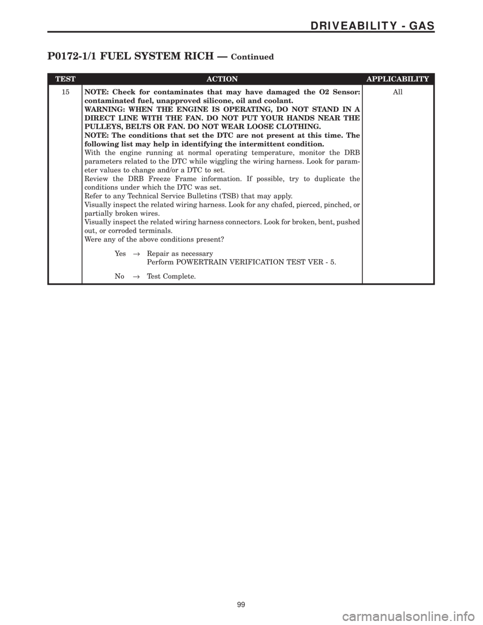
TEST ACTION APPLICABILITY
15NOTE: Check for contaminates that may have damaged the O2 Sensor:
contaminated fuel, unapproved silicone, oil and coolant.
WARNING: WHEN THE ENGINE IS OPERATING, DO NOT STAND IN A
DIRECT LINE WITH THE FAN. DO NOT PUT YOUR HANDS NEAR THE
PULLEYS, BELTS OR FAN. DO NOT WEAR LOOSE CLOTHING.
NOTE: The conditions that set the DTC are not present at this time. The
following list may help in identifying the intermittent condition.
With the engine running at normal operating temperature, monitor the DRB
parameters related to the DTC while wiggling the wiring harness. Look for param-
eter values to change and/or a DTC to set.
Review the DRB Freeze Frame information. If possible, try to duplicate the
conditions under which the DTC was set.
Refer to any Technical Service Bulletins (TSB) that may apply.
Visually inspect the related wiring harness. Look for any chafed, pierced, pinched, or
partially broken wires.
Visually inspect the related wiring harness connectors. Look for broken, bent, pushed
out, or corroded terminals.
Were any of the above conditions present?All
Ye s®Repair as necessary
Perform POWERTRAIN VERIFICATION TEST VER - 5.
No®Test Complete.
99
DRIVEABILITY - GAS
P0172-1/1 FUEL SYSTEM RICH ÐContinued
Page 3895 of 4284
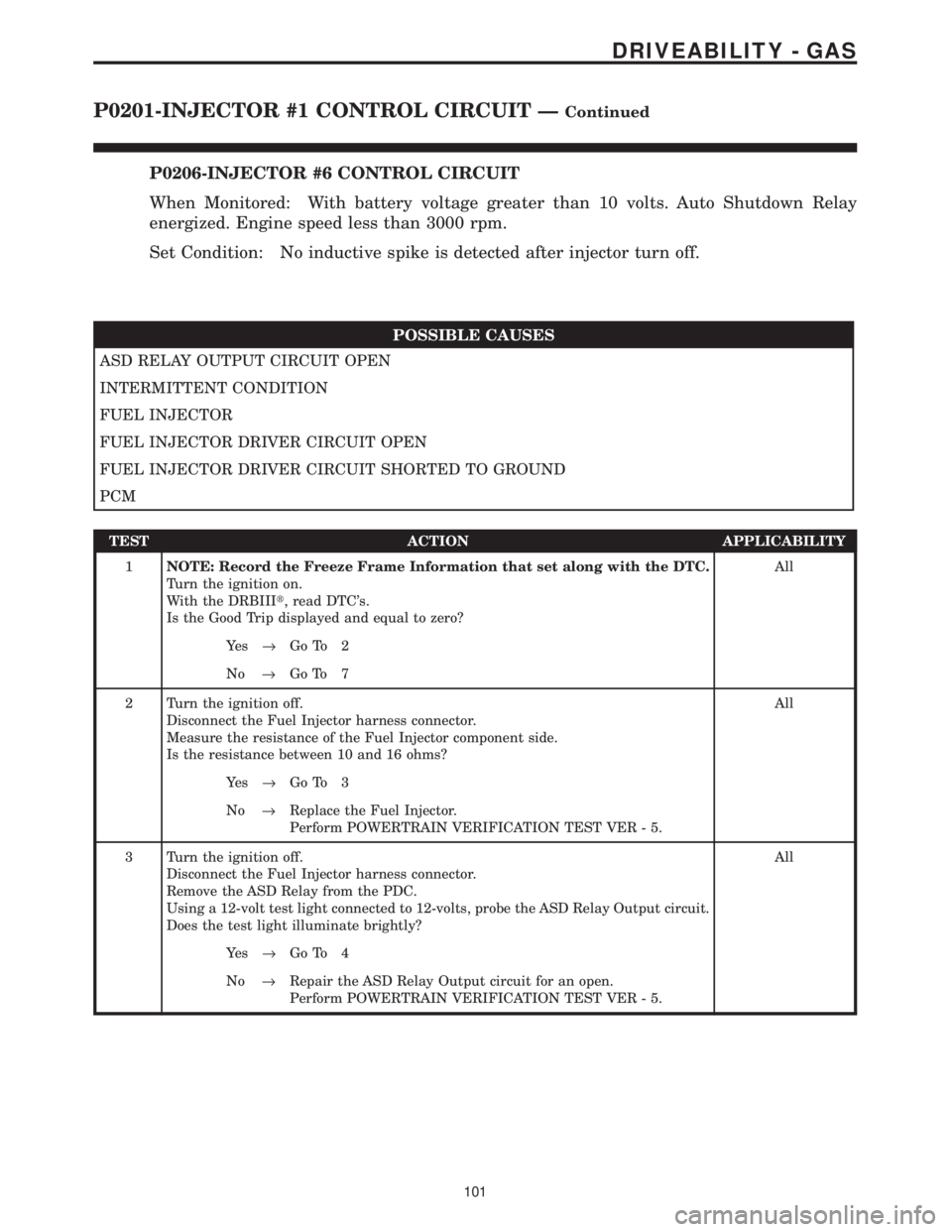
P0206-INJECTOR #6 CONTROL CIRCUIT
When Monitored: With battery voltage greater than 10 volts. Auto Shutdown Relay
energized. Engine speed less than 3000 rpm.
Set Condition: No inductive spike is detected after injector turn off.
POSSIBLE CAUSES
ASD RELAY OUTPUT CIRCUIT OPEN
INTERMITTENT CONDITION
FUEL INJECTOR
FUEL INJECTOR DRIVER CIRCUIT OPEN
FUEL INJECTOR DRIVER CIRCUIT SHORTED TO GROUND
PCM
TEST ACTION APPLICABILITY
1NOTE: Record the Freeze Frame Information that set along with the DTC.
Turn the ignition on.
With the DRBIIIt, read DTC's.
Is the Good Trip displayed and equal to zero?All
Ye s®Go To 2
No®Go To 7
2 Turn the ignition off.
Disconnect the Fuel Injector harness connector.
Measure the resistance of the Fuel Injector component side.
Is the resistance between 10 and 16 ohms?All
Ye s®Go To 3
No®Replace the Fuel Injector.
Perform POWERTRAIN VERIFICATION TEST VER - 5.
3 Turn the ignition off.
Disconnect the Fuel Injector harness connector.
Remove the ASD Relay from the PDC.
Using a 12-volt test light connected to 12-volts, probe the ASD Relay Output circuit.
Does the test light illuminate brightly?All
Ye s®Go To 4
No®Repair the ASD Relay Output circuit for an open.
Perform POWERTRAIN VERIFICATION TEST VER - 5.
101
DRIVEABILITY - GAS
P0201-INJECTOR #1 CONTROL CIRCUIT ÐContinued
Page 3896 of 4284
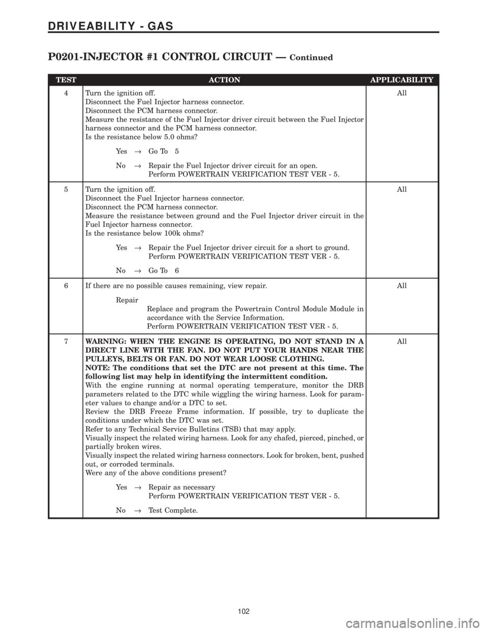
TEST ACTION APPLICABILITY
4 Turn the ignition off.
Disconnect the Fuel Injector harness connector.
Disconnect the PCM harness connector.
Measure the resistance of the Fuel Injector driver circuit between the Fuel Injector
harness connector and the PCM harness connector.
Is the resistance below 5.0 ohms?All
Ye s®Go To 5
No®Repair the Fuel Injector driver circuit for an open.
Perform POWERTRAIN VERIFICATION TEST VER - 5.
5 Turn the ignition off.
Disconnect the Fuel Injector harness connector.
Disconnect the PCM harness connector.
Measure the resistance between ground and the Fuel Injector driver circuit in the
Fuel Injector harness connector.
Is the resistance below 100k ohms?All
Ye s®Repair the Fuel Injector driver circuit for a short to ground.
Perform POWERTRAIN VERIFICATION TEST VER - 5.
No®Go To 6
6 If there are no possible causes remaining, view repair. All
Repair
Replace and program the Powertrain Control Module Module in
accordance with the Service Information.
Perform POWERTRAIN VERIFICATION TEST VER - 5.
7WARNING: WHEN THE ENGINE IS OPERATING, DO NOT STAND IN A
DIRECT LINE WITH THE FAN. DO NOT PUT YOUR HANDS NEAR THE
PULLEYS, BELTS OR FAN. DO NOT WEAR LOOSE CLOTHING.
NOTE: The conditions that set the DTC are not present at this time. The
following list may help in identifying the intermittent condition.
With the engine running at normal operating temperature, monitor the DRB
parameters related to the DTC while wiggling the wiring harness. Look for param-
eter values to change and/or a DTC to set.
Review the DRB Freeze Frame information. If possible, try to duplicate the
conditions under which the DTC was set.
Refer to any Technical Service Bulletins (TSB) that may apply.
Visually inspect the related wiring harness. Look for any chafed, pierced, pinched, or
partially broken wires.
Visually inspect the related wiring harness connectors. Look for broken, bent, pushed
out, or corroded terminals.
Were any of the above conditions present?All
Ye s®Repair as necessary
Perform POWERTRAIN VERIFICATION TEST VER - 5.
No®Test Complete.
102
DRIVEABILITY - GAS
P0201-INJECTOR #1 CONTROL CIRCUIT ÐContinued