2001 CHRYSLER VOYAGER wheel bolt torque
[x] Cancel search: wheel bolt torquePage 2961 of 4284
(14) If equipped, install the power steering cooler
hoses on the cooler inlet and outlet tubes. Install the
clamps.
(15) Install the front tire and wheel assemblies on
vehicle. Install the wheel mounting lug nuts and
tighten to a torque to 135 N´m (100 ft. lbs.).
(16) Lower the vehicle to a level were the interior
of vehicle is accessible (keeping tires off the ground).
(17) Using the intermediate coupler, turn the front
wheels of the vehicle to the left until the intermedi-
ate coupler shaft is properly aligned with the steer-
ing column coupler. Assemble the steering columnshaft coupler onto the steering gear intermediate
coupler (Fig. 1). Install steering column coupler to
intermediate shaft retaining pinch bolt. Tighten the
pinch bolt nut to a torque of 28 N´m (250 in. lbs.).
(18) Perform the POWER STEERING PUMP INI-
TIAL OPERATION procedure to properly fill and
bleed the power steering system. (Refer to 19 -
STEERING/PUMP - STANDARD PROCEDURE)
(19) Inspect for leaks.
(20) Adjust front wheel toe (Refer to 2 - SUSPEN-
SION/WHEEL ALIGNMENT - STANDARD PROCE-
DURE).
RGGEAR19a-5
GEAR (Continued)
Page 3002 of 4284
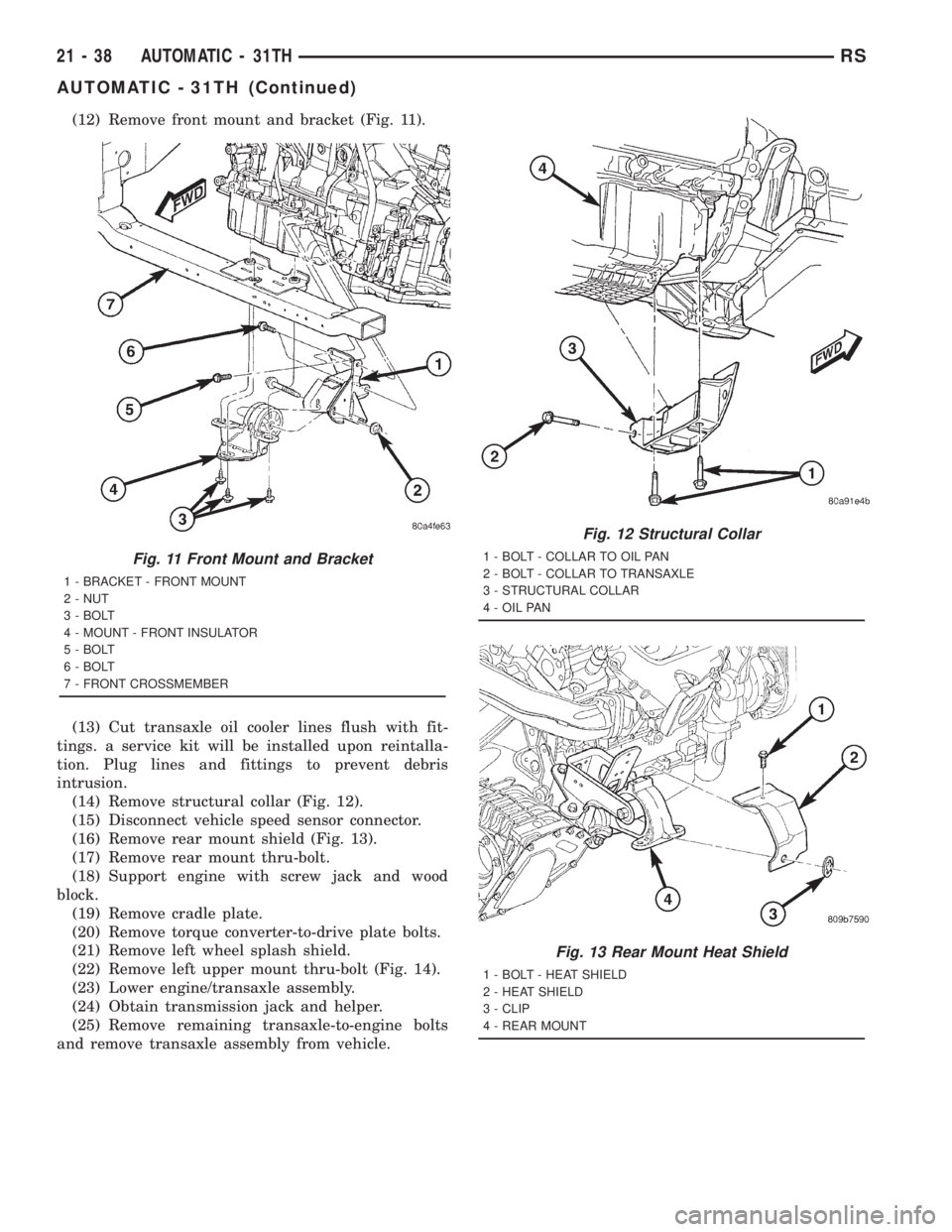
(12) Remove front mount and bracket (Fig. 11).
(13) Cut transaxle oil cooler lines flush with fit-
tings. a service kit will be installed upon reintalla-
tion. Plug lines and fittings to prevent debris
intrusion.
(14) Remove structural collar (Fig. 12).
(15) Disconnect vehicle speed sensor connector.
(16) Remove rear mount shield (Fig. 13).
(17) Remove rear mount thru-bolt.
(18) Support engine with screw jack and wood
block.
(19) Remove cradle plate.
(20) Remove torque converter-to-drive plate bolts.
(21) Remove left wheel splash shield.
(22) Remove left upper mount thru-bolt (Fig. 14).
(23) Lower engine/transaxle assembly.
(24) Obtain transmission jack and helper.
(25) Remove remaining transaxle-to-engine bolts
and remove transaxle assembly from vehicle.
Fig. 11 Front Mount and Bracket
1 - BRACKET - FRONT MOUNT
2 - NUT
3 - BOLT
4 - MOUNT - FRONT INSULATOR
5 - BOLT
6 - BOLT
7 - FRONT CROSSMEMBER
Fig. 12 Structural Collar
1 - BOLT - COLLAR TO OIL PAN
2 - BOLT - COLLAR TO TRANSAXLE
3 - STRUCTURAL COLLAR
4 - OIL PAN
Fig. 13 Rear Mount Heat Shield
1 - BOLT - HEAT SHIELD
2 - HEAT SHIELD
3 - CLIP
4 - REAR MOUNT
21 - 38 AUTOMATIC - 31THRS
AUTOMATIC - 31TH (Continued)
Page 3024 of 4284
(4) Install left wheel splash shield.
(5) Install torque converter-to-drive plate bolts and
torque to 88 N´m (65 ft. lbs.).
(6) Install cradle plate.
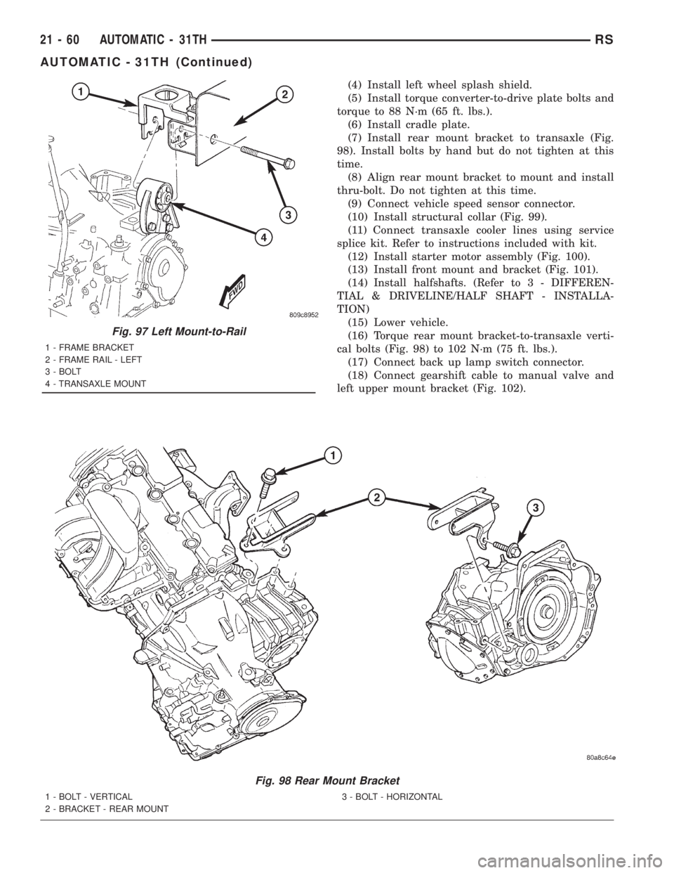
(7) Install rear mount bracket to transaxle (Fig.
98). Install bolts by hand but do not tighten at this
time.
(8) Align rear mount bracket to mount and install
thru-bolt. Do not tighten at this time.
(9) Connect vehicle speed sensor connector.
(10) Install structural collar (Fig. 99).
(11) Connect transaxle cooler lines using service
splice kit. Refer to instructions included with kit.
(12) Install starter motor assembly (Fig. 100).
(13) Install front mount and bracket (Fig. 101).
(14)
Install halfshafts. (Refer to 3 - DIFFEREN-
TIAL & DRIVELINE/HALF SHAFT - INSTALLA-
TION)
(15) Lower vehicle.
(16) Torque rear mount bracket-to-transaxle verti-
cal bolts (Fig. 98) to 102 N´m (75 ft. lbs.).
(17) Connect back up lamp switch connector.
(18) Connect gearshift cable to manual valve and
left upper mount bracket (Fig. 102).
Fig. 98 Rear Mount Bracket
1 - BOLT - VERTICAL
2 - BRACKET - REAR MOUNT3 - BOLT - HORIZONTAL
Fig. 97 Left Mount-to-Rail
1 - FRAME BRACKET
2 - FRAME RAIL - LEFT
3 - BOLT
4 - TRANSAXLE MOUNT
21 - 60 AUTOMATIC - 31THRS
AUTOMATIC - 31TH (Continued)
Page 3131 of 4284
(18) Remove left and right halfshaft assemblies.
(Refer to 3 - DIFFERENTIAL & DRIVELINE/HALF
SHAFT - REMOVAL)
(19) Disconnect exhaust pipe at manifold (Fig. 13).
(20) Remove cradle plate.
(21) AWD models: Remove power transfer unit.
(Refer to 21 - TRANSMISSION/TRANSAXLE/
POWER TRANSFER UNIT - REMOVAL)
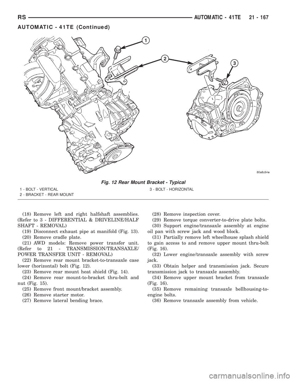
(22) Remove rear mount bracket-to-transaxle case
lower (horizontal) bolt (Fig. 12).
(23) Remove rear mount heat shield (Fig. 14).
(24) Remove rear mount-to-bracket thru-bolt and
nut (Fig. 15).
(25) Remove front mount/bracket assembly.
(26) Remove starter motor.
(27) Remove lateral bending brace.(28) Remove inspection cover.
(29) Remove torque converter-to-drive plate bolts.
(30) Support engine/transaxle assembly at engine
oil pan with screw jack and wood block.
(31) Partially remove left wheelhouse splash shield
to gain access to and remove upper mount thru-bolt
(Fig. 16).
(32) Lower engine/transaxle assembly with screw
jack.
(33) Obtain helper and transmission jack. Secure
transmission jack to transaxle assembly.
(34) Remove upper mount bracket from transaxle
(Fig. 16).
(35) Remove remaining transaxle bellhousing-to-
engine bolts.
(36) Remove transaxle assembly from vehicle.
Fig. 12 Rear Mount Bracket - Typical
1 - BOLT - VERTICAL
2 - BRACKET - REAR MOUNT3 - BOLT - HORIZONTAL
RSAUTOMATIC - 41TE21 - 167
AUTOMATIC - 41TE (Continued)
Page 3173 of 4284
INSTALLATION
NOTE: If transaxle assembly has been replaced or
overhauled (clutch and/or seal replacement), it is
necessary to perfrom the TCM Quick Learn proce-
dure. (Refer to 8 - ELECTRICAL/ELECTRONIC CON-
TROL MODULES/TRANSMISSION CONTROL
MODULE - STANDARD PROCEDURE)
NOTE: If torque converter assembly has been
replaced, it is necessary to reset the TCC Break-In
Strategy. (Refer to 8 - ELECTRICAL/ELECTRONIC
CONTROL MODULES/TRANSMISSION CONTROL
MODULE - STANDARD PROCEDURE)
(1) Using a transmission jack and a helper, posi-
tion transaxle assembly to engine. Install and torque
bolts to 95 N´m (70 ft. lbs.).
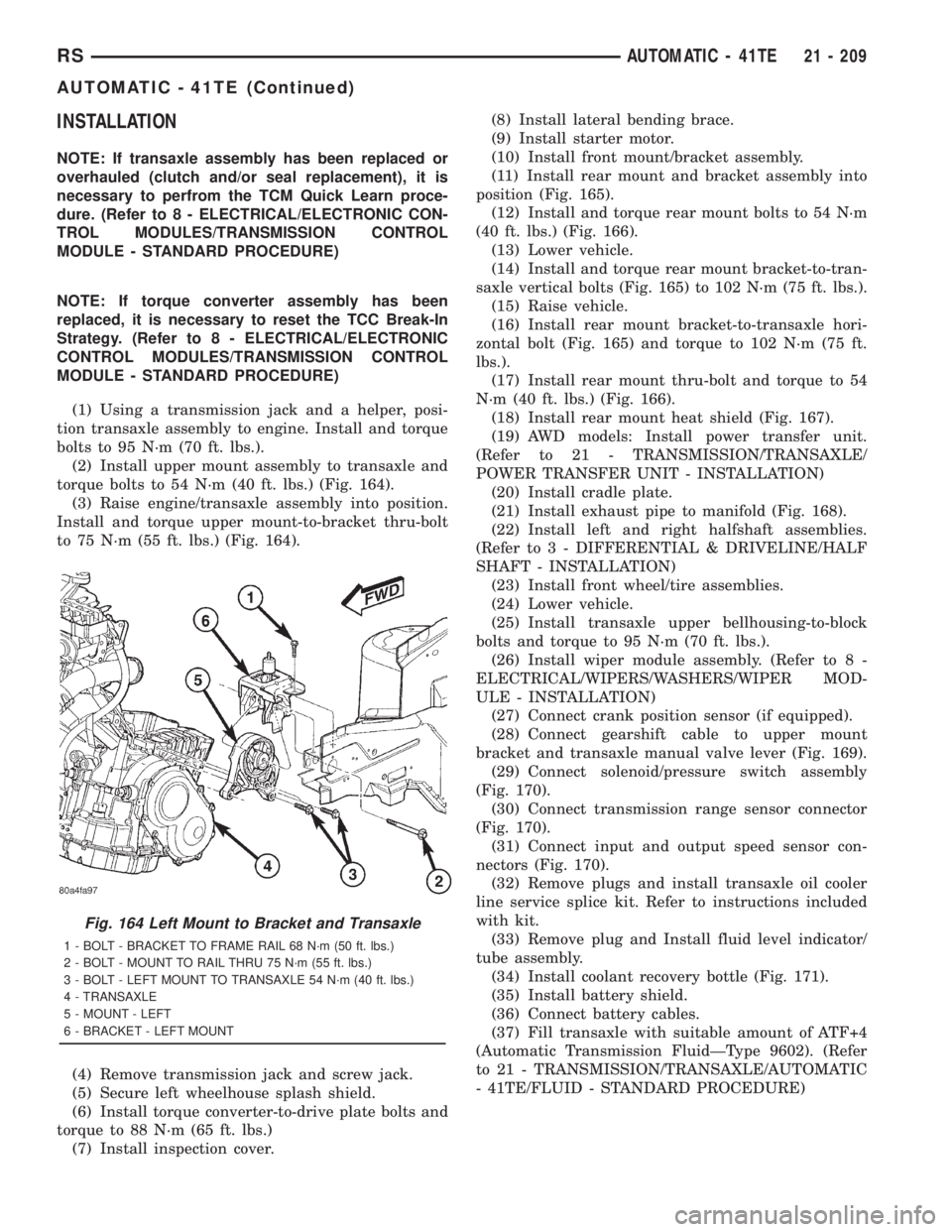
(2) Install upper mount assembly to transaxle and
torque bolts to 54 N´m (40 ft. lbs.) (Fig. 164).
(3) Raise engine/transaxle assembly into position.
Install and torque upper mount-to-bracket thru-bolt
to 75 N´m (55 ft. lbs.) (Fig. 164).
(4) Remove transmission jack and screw jack.
(5) Secure left wheelhouse splash shield.
(6) Install torque converter-to-drive plate bolts and
torque to 88 N´m (65 ft. lbs.)
(7) Install inspection cover.(8) Install lateral bending brace.
(9) Install starter motor.
(10) Install front mount/bracket assembly.
(11) Install rear mount and bracket assembly into
position (Fig. 165).
(12) Install and torque rear mount bolts to 54 N´m
(40 ft. lbs.) (Fig. 166).
(13) Lower vehicle.
(14) Install and torque rear mount bracket-to-tran-
saxle vertical bolts (Fig. 165) to 102 N´m (75 ft. lbs.).
(15) Raise vehicle.
(16) Install rear mount bracket-to-transaxle hori-
zontal bolt (Fig. 165) and torque to 102 N´m (75 ft.
lbs.).
(17) Install rear mount thru-bolt and torque to 54
N´m (40 ft. lbs.) (Fig. 166).
(18) Install rear mount heat shield (Fig. 167).
(19) AWD models: Install power transfer unit.
(Refer to 21 - TRANSMISSION/TRANSAXLE/
POWER TRANSFER UNIT - INSTALLATION)
(20) Install cradle plate.
(21) Install exhaust pipe to manifold (Fig. 168).
(22) Install left and right halfshaft assemblies.
(Refer to 3 - DIFFERENTIAL & DRIVELINE/HALF
SHAFT - INSTALLATION)
(23) Install front wheel/tire assemblies.
(24) Lower vehicle.
(25) Install transaxle upper bellhousing-to-block
bolts and torque to 95 N´m (70 ft. lbs.).
(26) Install wiper module assembly. (Refer to 8 -
ELECTRICAL/WIPERS/WASHERS/WIPER MOD-
ULE - INSTALLATION)
(27) Connect crank position sensor (if equipped).
(28) Connect gearshift cable to upper mount
bracket and transaxle manual valve lever (Fig. 169).
(29) Connect solenoid/pressure switch assembly
(Fig. 170).
(30) Connect transmission range sensor connector
(Fig. 170).
(31) Connect input and output speed sensor con-
nectors (Fig. 170).
(32) Remove plugs and install transaxle oil cooler
line service splice kit. Refer to instructions included
with kit.
(33) Remove plug and Install fluid level indicator/
tube assembly.
(34) Install coolant recovery bottle (Fig. 171).
(35) Install battery shield.
(36) Connect battery cables.
(37) Fill transaxle with suitable amount of ATF+4
(Automatic Transmission FluidÐType 9602). (Refer
to 21 - TRANSMISSION/TRANSAXLE/AUTOMATIC
- 41TE/FLUID - STANDARD PROCEDURE)
Fig. 164 Left Mount to Bracket and Transaxle
1 - BOLT - BRACKET TO FRAME RAIL 68 N´m (50 ft. lbs.)
2 - BOLT - MOUNT TO RAIL THRU 75 N´m (55 ft. lbs.)
3 - BOLT - LEFT MOUNT TO TRANSAXLE 54 N´m (40 ft. lbs.)
4 - TRANSAXLE
5 - MOUNT - LEFT
6 - BRACKET - LEFT MOUNT
RSAUTOMATIC - 41TE21 - 209
AUTOMATIC - 41TE (Continued)
Page 3298 of 4284
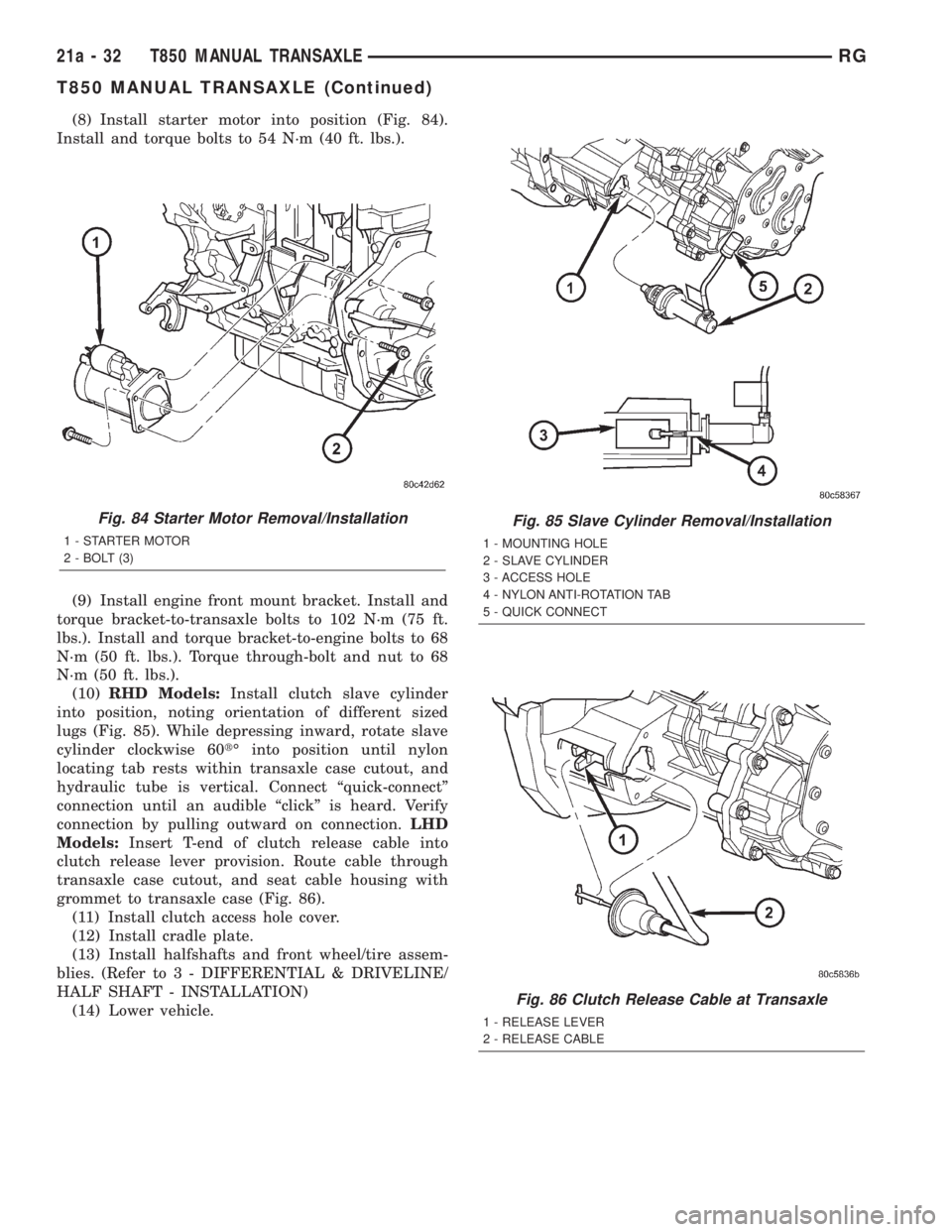
(8) Install starter motor into position (Fig. 84).
Install and torque bolts to 54 N´m (40 ft. lbs.).
(9) Install engine front mount bracket. Install and
torque bracket-to-transaxle bolts to 102 N´m (75 ft.
lbs.). Install and torque bracket-to-engine bolts to 68
N´m (50 ft. lbs.). Torque through-bolt and nut to 68
N´m (50 ft. lbs.).
(10)RHD Models:Install clutch slave cylinder
into position, noting orientation of different sized
lugs (Fig. 85). While depressing inward, rotate slave
cylinder clockwise 60tÉ into position until nylon
locating tab rests within transaxle case cutout, and
hydraulic tube is vertical. Connect ªquick-connectº
connection until an audible ªclickº is heard. Verify
connection by pulling outward on connection.LHD
Models:Insert T-end of clutch release cable into
clutch release lever provision. Route cable through
transaxle case cutout, and seat cable housing with
grommet to transaxle case (Fig. 86).
(11) Install clutch access hole cover.
(12) Install cradle plate.
(13) Install halfshafts and front wheel/tire assem-
blies. (Refer to 3 - DIFFERENTIAL & DRIVELINE/
HALF SHAFT - INSTALLATION)
(14) Lower vehicle.
Fig. 84 Starter Motor Removal/Installation
1 - STARTER MOTOR
2 - BOLT (3)
Fig. 85 Slave Cylinder Removal/Installation
1 - MOUNTING HOLE
2 - SLAVE CYLINDER
3 - ACCESS HOLE
4 - NYLON ANTI-ROTATION TAB
5 - QUICK CONNECT
Fig. 86 Clutch Release Cable at Transaxle
1 - RELEASE LEVER
2 - RELEASE CABLE
21a - 32 T850 MANUAL TRANSAXLERG
T850 MANUAL TRANSAXLE (Continued)
Page 3301 of 4284
(8) Install engine front mount bracket. Install and
torque bracket-to-transaxle bolts to 102 N´m (75 ft.
lbs.). Install and torque bracket-to-engine bolts to 68
N´m (50 ft. lbs.). Torque through-bolt and nut to 68
N´m (50 ft. lbs.).
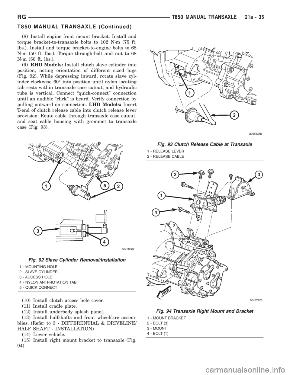
(9)RHD Models:Install clutch slave cylinder into
position, noting orientation of different sized lugs
(Fig. 92). While depressing inward, rotate slave cyl-
inder clockwise 60É into position until nylon locating
tab rests within transaxle case cutout, and hydraulic
tube is vertical. Connect ªquick-connectº connection
until an audible ªclickº is heard. Verify connection by
pulling outward on connection.LHD Models:Insert
T-end of clutch release cable into clutch release lever
provision. Route cable through transaxle case cutout,
and seat cable housing with grommet to transaxle
case (Fig. 93).
(10) Install clutch access hole cover.
(11) Install cradle plate.
(12) Install underbody splash panel.
(13) Install halfshafts and front wheel/tire assem-
blies. (Refer to 3 - DIFFERENTIAL & DRIVELINE/
HALF SHAFT - INSTALLATION)
(14) Lower vehicle.
(15) Install right mount bracket to transaxle (Fig.
94).
Fig. 92 Slave Cylinder Removal/Installation
1 - MOUNTING HOLE
2 - SLAVE CYLINDER
3 - ACCESS HOLE
4 - NYLON ANTI-ROTATION TAB
5 - QUICK CONNECT
Fig. 93 Clutch Release Cable at Transaxle
1 - RELEASE LEVER
2 - RELEASE CABLE
Fig. 94 Transaxle Right Mount and Bracket
1 - MOUNT BRACKET
2 - BOLT (3)
3 - MOUNT
4 - BOLT (1)
RGT850 MANUAL TRANSAXLE21a-35
T850 MANUAL TRANSAXLE (Continued)
Page 3309 of 4284
BACK-UP LAMP SWITCH
REMOVAL
(1) Raise vehicle on hoist.
(2) Disconnect back-up lamp switch connector.
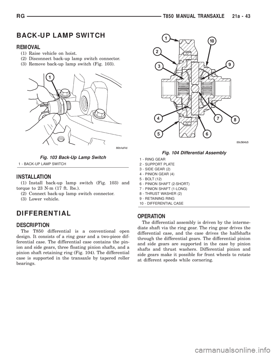
(3) Remove back-up lamp switch (Fig. 103).
INSTALLATION
(1) Install back-up lamp switch (Fig. 103) and
torque to 23 N´m (17 ft. lbs.).
(2) Connect back-up lamp switch connector.
(3) Lower vehicle.
DIFFERENTIAL
DESCRIPTION
The T850 differential is a conventional open
design. It consists of a ring gear and a two-piece dif-
ferential case. The differential case contains the pin-
ion and side gears, three floating pinion shafts, and a
pinion shaft retaining ring (Fig. 104). The differential
case is supported in the transaxle by tapered roller
bearings.
OPERATION
The differential assembly is driven by the interme-
diate shaft via the ring gear. The ring gear drives the
differential case, and the case drives the halfshafts
through the differential gears. The differential pinion
and side gears are supported in the case by pinion
shafts and thrust washers. Differential pinion and
side gears make it possible for front wheels to rotate
at different speeds while cornering.
Fig. 103 Back-Up Lamp Switch
1 - BACK-UP LAMP SWITCH
Fig. 104 Differential Assembly
1 - RING GEAR
2 - SUPPORT PLATE
3 - SIDE GEAR (2)
4 - PINION GEAR (4)
5 - BOLT (12)
6 - PINION SHAFT (2-SHORT)
7 - PINION SHAFT (1-LONG)
8 - THRUST WASHER (2)
9 - RETAINING RING
10 - DIFFERENTIAL CASE
RGT850 MANUAL TRANSAXLE21a-43