2001 CHRYSLER VOYAGER clock
[x] Cancel search: clockPage 1787 of 4284
INSTALLATION-POWER STEERING BELT
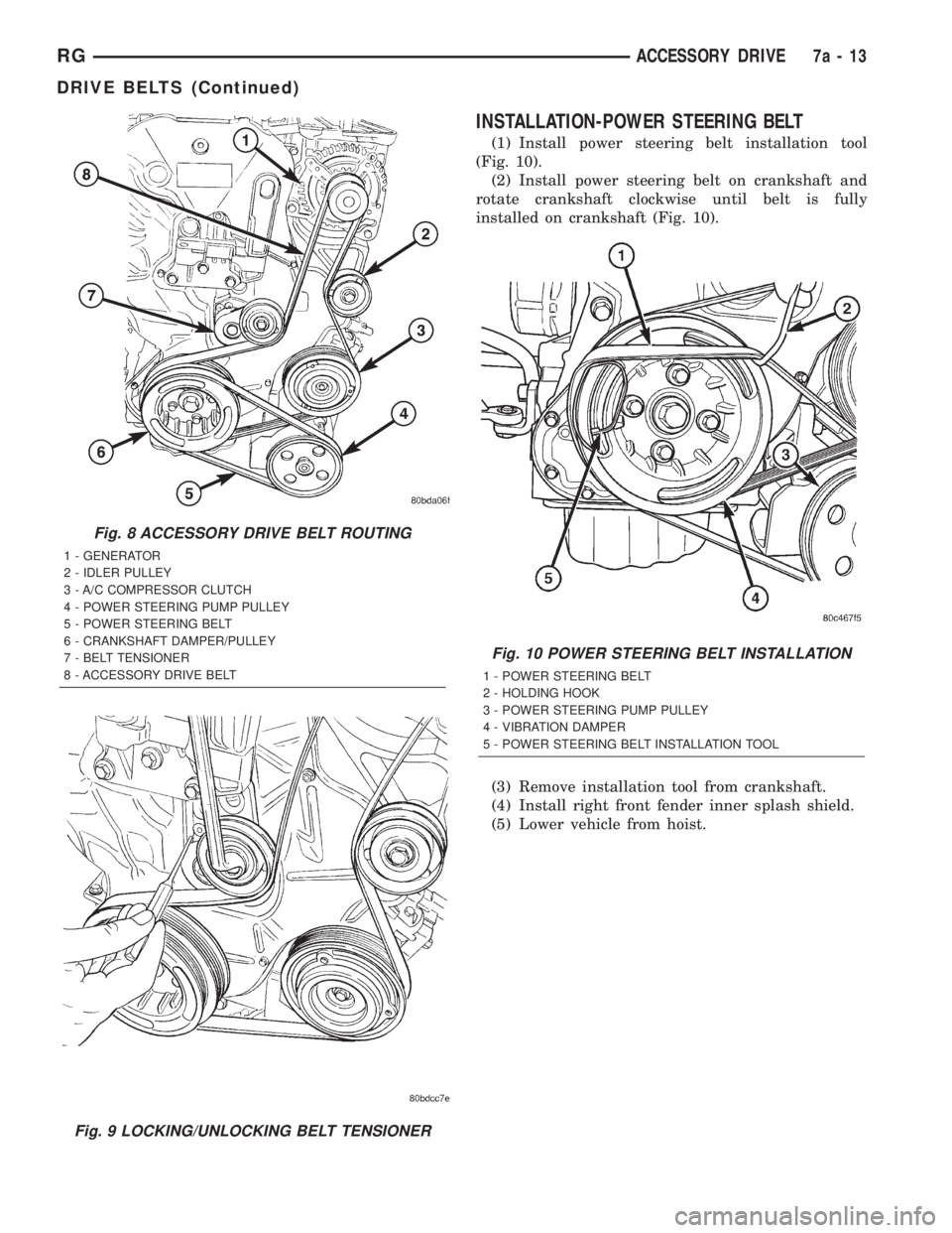
(1) Install power steering belt installation tool
(Fig. 10).
(2) Install power steering belt on crankshaft and
rotate crankshaft clockwise until belt is fully
installed on crankshaft (Fig. 10).
(3) Remove installation tool from crankshaft.
(4) Install right front fender inner splash shield.
(5) Lower vehicle from hoist.
Fig. 8 ACCESSORY DRIVE BELT ROUTING
1 - GENERATOR
2 - IDLER PULLEY
3 - A/C COMPRESSOR CLUTCH
4 - POWER STEERING PUMP PULLEY
5 - POWER STEERING BELT
6 - CRANKSHAFT DAMPER/PULLEY
7 - BELT TENSIONER
8 - ACCESSORY DRIVE BELT
Fig. 9 LOCKING/UNLOCKING BELT TENSIONER
Fig. 10 POWER STEERING BELT INSTALLATION
1 - POWER STEERING BELT
2 - HOLDING HOOK
3 - POWER STEERING PUMP PULLEY
4 - VIBRATION DAMPER
5 - POWER STEERING BELT INSTALLATION TOOL
RGACCESSORY DRIVE7a-13
DRIVE BELTS (Continued)
Page 1796 of 4284
RADIATOR DRAINCOCK
REMOVAL
CAUTION: Use of pliers on draincock is not recom-
mended. Damage may occur to radiator or drain-
cock.
NOTE: It is not necessary to remove draincock dur-
ing a routine coolant drain.
(1) Drain the cooling system (Refer to 7 - COOL-
ING/ENGINE/COOLANT - STANDARD PROCE-
DURE).
(2) Open the draincock by turning it counterclock-
wise until it stops.
(3) Turn the draincock back (clockwise) 1/8 turn.
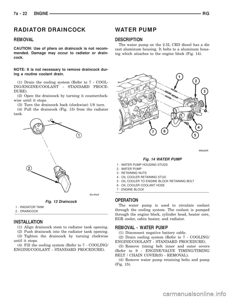
(4) Pull the draincock (Fig. 13) from the radiator
tank.
INSTALLATION
(1) Align draincock stem to radiator tank opening.
(2) Push draincock into the radiator tank opening.
(3) Tighten the draincock by turning clockwise
until it stops.
(4) Fill the cooling system (Refer to 7 - COOLING/
ENGINE/COOLANT - STANDARD PROCEDURE).
WATER PUMP
DESCRIPTION
The water pump on the 2.5L CRD diesel has a die
cast aluminum housing. It bolts to a aluminum hous-
ing which attaches to the engine block (Fig. 14).
OPERATION
The water pump is used to circulate coolant
through the cooling system. The coolant is pumped
through the engine block, cylinder head, heater core,
EGR cooler, cabin heater, and radiator.
REMOVAL - WATER PUMP
(1) Disconnect negative battery cable.
(2) Drain cooling system (Refer to 7 - COOLING/
ENGINE/COOLANT - STANDARD PROCEDURE).
(3) Remove timing belt inner and outer covers
(Refer to 9 - ENGINE/VALVE TIMING/TIMING
BELT / CHAIN COVER(S) - REMOVAL).
(4) Remove water pump retaining bolts and pump
(Fig. 15).
Fig. 13 Draincock
1 - RADIATOR TANK
2 - DRAINCOCK
Fig. 14 WATER PUMP
1 - WATER PUMP HOUSING STUDS
2 - WATER PUMP
3 - RETAINING NUTS
4 - OIL COOLER RETAINING STUD
5 - OIL COOLER TO ENGINE BLOCK RETAINING BOLT
6 - OIL COOLER COOLANT HOSE
7 - ENGINE BLOCK
7a - 22 ENGINERG
Page 1799 of 4284
DIAGNOSIS AND TESTING - COOLING SYSTEM
PRESSURE CAP
Dip the pressure cap in water. Clean any deposits
off the vent valve or its seat and apply cap to end of
the Pressure Cap Test Adaptor that is included with
the Cooling System Tester 7700. Working the
plunger, bring the pressure to 104 kPa (15 psi) on the
gauge. If the pressure cap fails to hold pressure of at
least 97 kPa (14 psi), replace the pressure cap.
CAUTION: The Cooling System Tester Tool is very
sensitive to small air leaks that will not cause cool-
ing system problems. A pressure cap that does not
have a history of coolant loss should not be
replaced just because it leaks slowly when tested
with this tool. Add water to the tool. Turn tool
upside down and recheck pressure cap to confirm
that cap is bad.
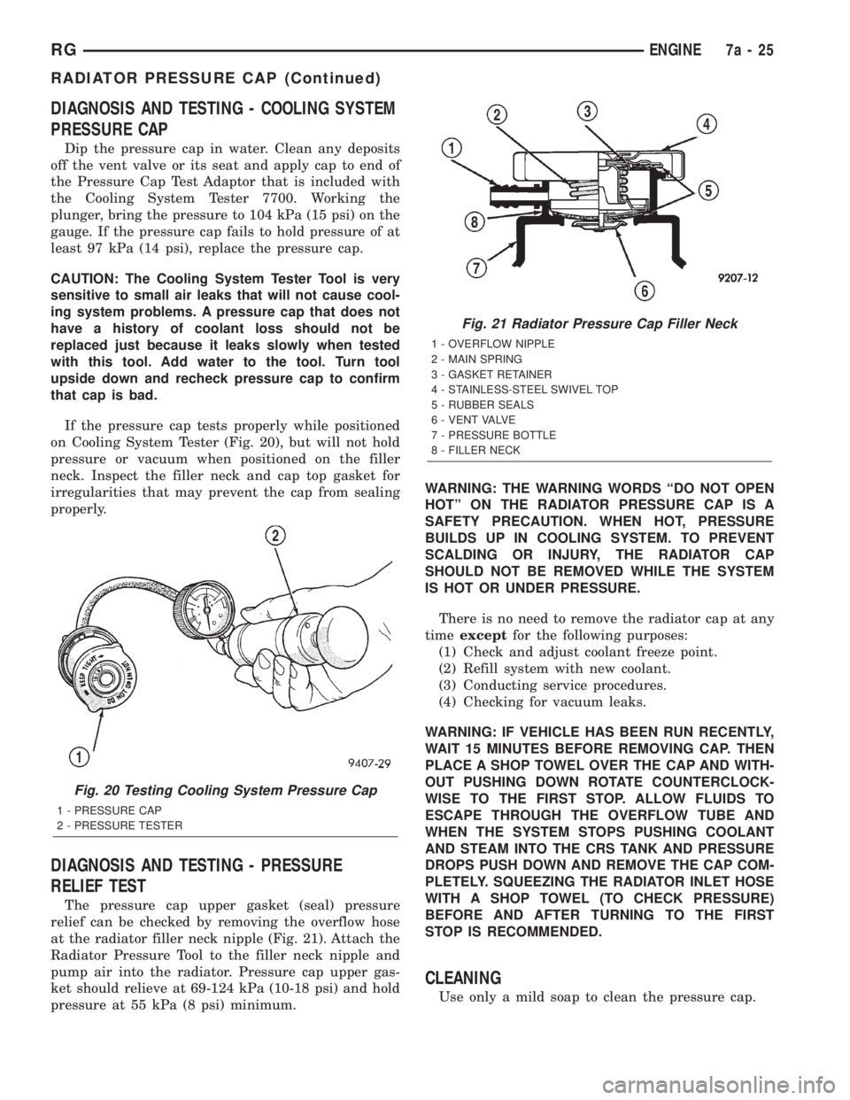
If the pressure cap tests properly while positioned
on Cooling System Tester (Fig. 20), but will not hold
pressure or vacuum when positioned on the filler
neck. Inspect the filler neck and cap top gasket for
irregularities that may prevent the cap from sealing
properly.
DIAGNOSIS AND TESTING - PRESSURE
RELIEF TEST
The pressure cap upper gasket (seal) pressure
relief can be checked by removing the overflow hose
at the radiator filler neck nipple (Fig. 21). Attach the
Radiator Pressure Tool to the filler neck nipple and
pump air into the radiator. Pressure cap upper gas-
ket should relieve at 69-124 kPa (10-18 psi) and hold
pressure at 55 kPa (8 psi) minimum.WARNING: THE WARNING WORDS ªDO NOT OPEN
HOTº ON THE RADIATOR PRESSURE CAP IS A
SAFETY PRECAUTION. WHEN HOT, PRESSURE
BUILDS UP IN COOLING SYSTEM. TO PREVENT
SCALDING OR INJURY, THE RADIATOR CAP
SHOULD NOT BE REMOVED WHILE THE SYSTEM
IS HOT OR UNDER PRESSURE.
There is no need to remove the radiator cap at any
timeexceptfor the following purposes:
(1) Check and adjust coolant freeze point.
(2) Refill system with new coolant.
(3) Conducting service procedures.
(4) Checking for vacuum leaks.
WARNING: IF VEHICLE HAS BEEN RUN RECENTLY,
WAIT 15 MINUTES BEFORE REMOVING CAP. THEN
PLACE A SHOP TOWEL OVER THE CAP AND WITH-
OUT PUSHING DOWN ROTATE COUNTERCLOCK-
WISE TO THE FIRST STOP. ALLOW FLUIDS TO
ESCAPE THROUGH THE OVERFLOW TUBE AND
WHEN THE SYSTEM STOPS PUSHING COOLANT
AND STEAM INTO THE CRS TANK AND PRESSURE
DROPS PUSH DOWN AND REMOVE THE CAP COM-
PLETELY. SQUEEZING THE RADIATOR INLET HOSE
WITH A SHOP TOWEL (TO CHECK PRESSURE)
BEFORE AND AFTER TURNING TO THE FIRST
STOP IS RECOMMENDED.
CLEANING
Use only a mild soap to clean the pressure cap.
Fig. 20 Testing Cooling System Pressure Cap
1 - PRESSURE CAP
2 - PRESSURE TESTER
Fig. 21 Radiator Pressure Cap Filler Neck
1 - OVERFLOW NIPPLE
2 - MAIN SPRING
3 - GASKET RETAINER
4 - STAINLESS-STEEL SWIVEL TOP
5 - RUBBER SEALS
6 - VENT VALVE
7 - PRESSURE BOTTLE
8 - FILLER NECK
RGENGINE7a-25
RADIATOR PRESSURE CAP (Continued)
Page 1805 of 4284
AUDIO
TABLE OF CONTENTS
page page
AUDIO
DESCRIPTION............................1
OPERATION.............................1
DIAGNOSIS AND TESTING..................1
ANTENNA BODY & CABLE
DESCRIPTION............................3
OPERATION.............................3
DIAGNOSIS AND TESTING..................3
REMOVAL...............................4
INSTALLATION............................4
CD CHANGER
DESCRIPTION............................6
OPERATION.............................6
REMOVAL...............................6
INSTALLATION............................6
CHOKE
DIAGNOSIS AND TESTING..................6
D-PILLAR SPEAKER
REMOVAL...............................6
INSTALLATION............................7
DASH PANEL SPEAKER
REMOVAL...............................7INSTALLATION............................7
DOOR MOUNTED SPEAKER
REMOVAL...............................7
INSTALLATION............................7
QUARTER PANEL SPEAKER
REMOVAL...............................8
INSTALLATION............................8
RADIO
DIAGNOSIS AND TESTING..................8
REMOVAL...............................9
INSTALLATION............................9
RADIO NOISE SUPPRESSION COMPONENTS
DESCRIPTION............................9
OPERATION.............................9
REMOTE SWITCHES
DESCRIPTION...........................10
OPERATION.............................10
DIAGNOSIS AND TESTING.................11
REMOVAL..............................11
INSTALLATION...........................12
AUDIO
DESCRIPTION
There are four different system combinations avail-
able on the RS models. The available radio options
are:
²AM/FM Cassette
²AM/FM Compact Disc with Compact Disc
Changer
²AM/FM Cassette with single Compact Disc
Player
²AM/FM Cassette with Compact Disc Changer
All factory installed radio receivers are stereo Elec-
tronically Tuned Radios (ETR) and include and elec-
tronic digital clock function.
OPERATION
Operating instructions for the factory installed
audio systems can be found in the Owner's Manual
provided with this vehicle.
DIAGNOSIS AND TESTING
WARNING:
ON VEHICLES EQUIPPED WITH AIRBAGS, REFER
TO ELECTRICAL, RESTRAINTS BEFORE ATTEMPT-
ING ANY STEERING WHEEL, STEERING COLUMN,
OR INSTRUMENT PANEL COMPONENT DIAGNOSIS
OR SERVICE. FAILURE TO TAKE THE PROPER
PRECAUTIONS COULD RESULT IN ACCIDENTAL
AIRBAG DEPLOYMENT AND POSSIBLE PERSONAL
INJURY.
RSAUDIO8A-1
Page 1814 of 4284
REMOTE SWITCHES
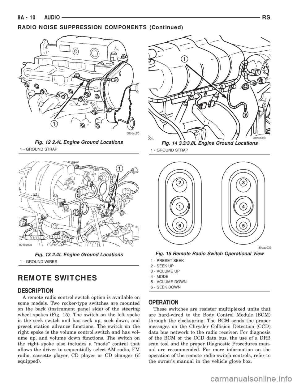
DESCRIPTION
A remote radio control switch option is available on
some models. Two rocker-type switches are mounted
on the back (instrument panel side) of the steering
wheel spokes (Fig. 15). The switch on the left spoke
is the seek switch and has seek up, seek down, and
preset station advance functions. The switch on the
right spoke is the volume control switch and has vol-
ume up, and volume down functions. The switch on
the right spoke also includes a ªmodeº control that
allows the driver to sequentially select AM radio, FM
radio, cassette player, CD player or CD changer (if
equipped).
OPERATION
These switches are resistor multiplexed units that
are hard-wired to the Body Control Module (BCM)
through the clockspring. The BCM sends the proper
messages on the Chrysler Collision Detection (CCD)
data bus network to the radio receiver. For diagnosis
of the BCM or the CCD data bus, the use of a DRB
scan tool and the proper Diagnostic Procedures man-
ual are recommended. For more information on the
operation of the remote radio switch controls, refer to
the owner's manual in the vehicle glove box.
Fig. 12 2.4L Engine Ground Locations
1 - GROUND STRAP
Fig. 13 2.4L Engine Ground Locations
1 - GROUND WIRES
Fig. 14 3.3/3.8L Engine Ground Locations
1 - GROUND STRAP
Fig. 15 Remote Radio Switch Operational View
1 - PRESET SEEK
2 - SEEK UP
3 - VOLUME UP
4 - MODE
5 - VOLUME DOWN
6 - SEEK DOWN
8A - 10 AUDIORS
RADIO NOISE SUPPRESSION COMPONENTS (Continued)
Page 1868 of 4284
(4) Allow the battery to stabilize to open-circuit
voltage. It may take up to five minutes for the bat-
tery voltage to stabilize.
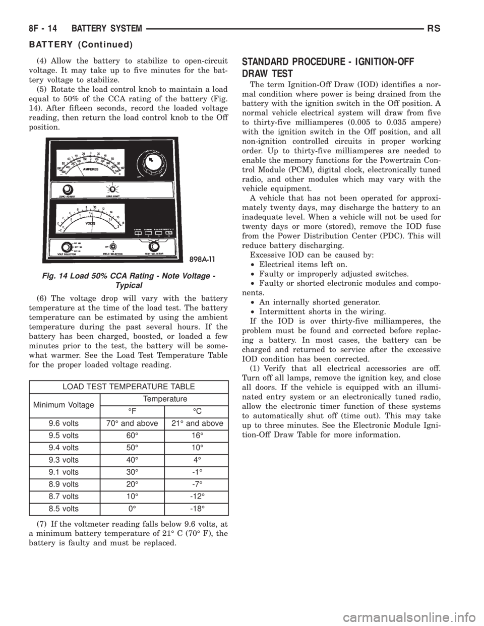
(5) Rotate the load control knob to maintain a load
equal to 50% of the CCA rating of the battery (Fig.
14). After fifteen seconds, record the loaded voltage
reading, then return the load control knob to the Off
position.
(6) The voltage drop will vary with the battery
temperature at the time of the load test. The battery
temperature can be estimated by using the ambient
temperature during the past several hours. If the
battery has been charged, boosted, or loaded a few
minutes prior to the test, the battery will be some-
what warmer. See the Load Test Temperature Table
for the proper loaded voltage reading.
LOAD TEST TEMPERATURE TABLE
Minimum VoltageTemperature
ÉF ÉC
9.6 volts 70É and above 21É and above
9.5 volts 60É 16É
9.4 volts 50É 10É
9.3 volts 40É 4É
9.1 volts 30É -1É
8.9 volts 20É -7É
8.7 volts 10É -12É
8.5 volts 0É -18É
(7) If the voltmeter reading falls below 9.6 volts, at
a minimum battery temperature of 21É C (70É F), the
battery is faulty and must be replaced.
STANDARD PROCEDURE - IGNITION-OFF
DRAW TEST
The term Ignition-Off Draw (IOD) identifies a nor-
mal condition where power is being drained from the
battery with the ignition switch in the Off position. A
normal vehicle electrical system will draw from five
to thirty-five milliamperes (0.005 to 0.035 ampere)
with the ignition switch in the Off position, and all
non-ignition controlled circuits in proper working
order. Up to thirty-five milliamperes are needed to
enable the memory functions for the Powertrain Con-
trol Module (PCM), digital clock, electronically tuned
radio, and other modules which may vary with the
vehicle equipment.
A vehicle that has not been operated for approxi-
mately twenty days, may discharge the battery to an
inadequate level. When a vehicle will not be used for
twenty days or more (stored), remove the IOD fuse
from the Power Distribution Center (PDC). This will
reduce battery discharging.
Excessive IOD can be caused by:
²Electrical items left on.
²Faulty or improperly adjusted switches.
²Faulty or shorted electronic modules and compo-
nents.
²An internally shorted generator.
²Intermittent shorts in the wiring.
If the IOD is over thirty-five milliamperes, the
problem must be found and corrected before replac-
ing a battery. In most cases, the battery can be
charged and returned to service after the excessive
IOD condition has been corrected.
(1) Verify that all electrical accessories are off.
Turn off all lamps, remove the ignition key, and close
all doors. If the vehicle is equipped with an illumi-
nated entry system or an electronically tuned radio,
allow the electronic timer function of these systems
to automatically shut off (time out). This may take
up to three minutes. See the Electronic Module Igni-
tion-Off Draw Table for more information.
Fig. 14 Load 50% CCA Rating - Note Voltage -
Typical
8F - 14 BATTERY SYSTEMRS
BATTERY (Continued)
Page 1911 of 4284
HORN
TABLE OF CONTENTS
page page
HORN
DESCRIPTION............................1
OPERATION.............................1
DIAGNOSIS AND TESTING..................1
HORN
DIAGNOSIS AND TESTING..................3
REMOVAL...............................4INSTALLATION............................5
HORN RELAY
DIAGNOSIS AND TESTING..................5
REMOVAL...............................5
INSTALLATION............................5
HORN SWITCH
DESCRIPTION............................5
HORN
DESCRIPTION
HORN SYSTEM
WARNING:
ON VEHICLES EQUIPPED WITH AIRBAG, REFER TO
ELECTRICAL, RESTRAINTS FOR SAFETY PRECAU-
TIONS. DISCONNECT THE NEGATIVE CABLE FROM
THE BATTERY BEFORE SERVICING COMPONENTS
INVOLVING THE AIRBAG SYSTEM. ACCIDENTAL
DEPLOYMENT OF AIRBAG AND PERSONAL INJURY
CAN RESULT.
The horn circuit consists of a horn switch, clock-
spring, horn relay, horns and intelligent power mod-
ule. The horn switch is a membrane switch located in
the airbag trim cover. The horns are located forward
of the left front wheel behind the bumper fascia.
OPERATION
The horn relay plugs into the intelligent power
module which is located in the engine compartment.
For circuit information and component locations,
refer to the appropriate wiring information. The wir-
ing information includes wiring diagrams, proper
wire and connector repair procedures, details of wire
harness routing and retention, connector pin-out
information and location views for the various wire
harness connectors, splices and grounds.
The horns will not function if the switch is
ªCLOSEDº for more than 30 seconds. Once the
switch is ªOPENº, a 20±30 second delay will occur
before the horns are functional again.
DIAGNOSIS AND TESTING
Refer to Horn System Test below. If the horn does
not sound, check horn fuse located in the intelligent
power module. If the fuse is blown, replace with the
correct fuse. If the horns fail to sound and the new
fuse blows when depressing the horn switch, a short
circuit in the horn or the horn wiring between the
fuse terminal and the horn is responsible, or a defec-
tive horn switch allowed the horn to burn out is
responsible.
If the fuse is OK, test horn relay (Refer to 8 -
ELECTRICAL/HORN/HORN RELAY - DIAGNOSIS
AND TESTING).
If the relay is OK, test horn. Refer to Horn System
Test.
CAUTION:
Continuous sounding of horn may cause horn relay
to fail.
Should the horn sound continuously:
²Unplug the horn relay from intelligent power
module.
²Refer to (Refer to 8 - ELECTRICAL/HORN/
HORN RELAY - DIAGNOSIS AND TESTING).
Refer to the appropriate wiring information. The
wiring information includes wiring diagrams, proper
wire and connector repair procedures, details of wire
harness routing and retention, connector pin-out
information and location views for the various wire
harness connectors, splices and grounds.
RSHORN8H-1
Page 1912 of 4284
HORN SYSTEM TEST
CONDITION POSSIBLE CAUSE CORRECTION
HORN SOUNDS CONTINUOUSLY.
NOTE: IMMEDIATELY UNPLUG
HORN RELAY IN THE
INTELLIGENT POWER MODULE.(1) FAULTY HORN RELAY. (1) REFER TO HORN RELAY
TEST.
(2) HORN CONTROL CIRCUIT TO
RELAY SHORTED TO GROUND.(2) CHECK TERMINAL 85 IN
INTELLIGENT POWER MODULE
FOR CONTINUITY TO GROUND.
IF CONTINUITY TO GROUND
INDICATES:
(A) STEERING WHEEL HORN
SWITCH/LEAD SHORTED TO
GROUND.
(B) WIRING HARNESS SHORTED
TO GROUND. FIND THE SHORT
AND REPAIR AS NECESSARY.
(3) PINCHED HORN SWITCH
WIRE UNDER DRIVER AIRBAG
MODULE.(3) REPLACE DRIVER AIRBAG
MODULE TRIM.
(4) FAULTY HORN SWITCH. (4) REPLACE DRIVER AIRBAG
MODULE TRIM.
(5) FAULTY CLOCKSPRING. (5) REPLACE CLOCKSPRING.
HORN SOUND INTERMITTENTLY
AS THE STEERING WHEEL IS
TURNED.(1) HORN RELAY CONTROL
CIRCUIT X3 IS SHORTED TO
GROUND INSIDE STEERING
COLUMN OR WHEEL.(1) REMOVE DRIVER AIRBAG
MODULE AND/OR WHEEL.
CHECK FOR RUBBING OR
LOOSE WIRE/CONNECTOR,
REPAIR AS NECESSARY.
(2) PINCHED HORN SWITCH
WIRE UNDER DRIVER AIRBAG
MODULE.(2) REPLACE DRIVER AIRBAG
MODULE TRIM.
(3) FAULTY HORN SWITCH. (3) REPLACE DRIVER AIRBAG
MODULE TRIM.
(4) FAULTY CLOCKSPRING. (4) REPLACE CLOCKSPRING.
HORN DOES NOT SOUND (1) CHECK FUSE 8 IN
INTELLIGENT POWER MODULE.(1) REPLACE FUSE IF BLOWN
REPAIR AS NECESSARY.
(2) NO VOLTAGE AT HORN
RELAY TERMINALS 30 & 86, AND
FUSE IS OK.(2) NO VOLTAGE, REPAIR THE
CIRCUIT AS NECESSARY.
(3) OPEN CIRCUIT FROM
TERMINAL 85 OF THE HORN
RELAY TO HORN SWITCH, X3
CIRCUIT.(3) REPAIR CIRCUIT AS
NECESSARY.
(4) FAULTY OR DAMAGED HORN. (4) VOLTAGE AT HORN WHEN
HORN SWITCH IS PRESSED,
REPLACE HORN.
(5) FAULTY HORN SWITCH. (5) REPLACE DRIVER AIRBAG
MODULE TRIM.
(6) FAULTY CLOCKSPRING. (6) REPLACE CLOCKSPRING.
8H - 2 HORNRS
HORN (Continued)