2001 CHRYSLER VOYAGER check engine
[x] Cancel search: check enginePage 1017 of 4284
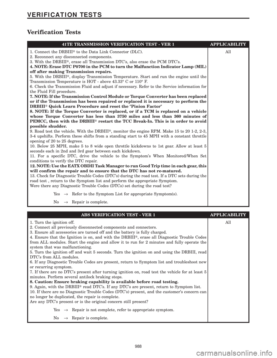
Verification Tests
41TE TRANSMISSION VERIFICATION TEST - VER 1 APPLICABILITY
1. Connect the DRBIIItto the Data Link Connector (DLC).
2. Reconnect any disconnected components.
3. With the DRBIIIt, erase all Transmission DTC's, also erase the PCM DTC's.
4. NOTE: Erase DTC P0700 in the PCM to turn the Malfunction Indicator Lamp (MIL)
off after making Transmission repairs.
5. With the DRBIIIt, display Transmission Temperature. Start and run the engine until the
Transmission Temperature is HOT - above 43.33É C or 110É F.
6. Check the Transmission Fluid and adjust if necessary. Refer to the Service information for
the Fluid Fill procedure.
7. NOTE: If the Transmission Control Module or Torque Converter has been replaced
or if the Transmission has been repaired or replaced it is necessary to perform the
DRBIIItQuick Learn Procedure and reset the(Pinion Factor(
8. NOTE: If the Torque Converter is replaced, or if a TCM is replaced on a vehicle
whose Torque Converter has less than 3750 miles and less than 360 minutes of
PEMCC, then with the DRBIIItrestart the TCC Break-In. This is in order to avoid
possible shudder.
9. Road test the vehicle. With the DRBIIIt, monitor the engine RPM. Make 15 to 20 1-2, 2-3,
3-4 upshifts. Perform these shifts from a standing start to 45 MPH with a constant throttle
opening of 20 to 25 degrees.
10. Below 25 MPH, make 5 to 8 wide open throttle kickdowns to 1st gear. Allow at least 5
seconds each in 2nd and 3rd gear between each kickdown.
11. For a specific DTC, drive the vehicle to the Symptom's When Monitored/When Set
conditions to verify the DTC repair.
12. NOTE: Use the EATX OBDII Task Manager to run Good Trip time in each gear, this
will confirm the repair and to ensure that the DTC has not re-matured.
13. Check for Diagnostic Trouble Codes (DTC's) during the road test. If a DTC sets during the
road test , return to the Symptom list and perform the appropriate Symptom.
Were there any Diagnostic Trouble Codes (DTCs) set during the road test?All
Ye s®Refer to the Symptom List for appropriate Symptom(s).
No®Repair is complete.
ABS VERIFICATION TEST - VER 1 APPLICABILITY
1. Turn the ignition off.
2. Connect all previously disconnected components and connectors.
3. Ensure all accessories are turned off and the battery is fully charged.
4. Ensure that the Ignition is on, and with the DRBIIIt, erase all Diagnostic Trouble Codes
from ALL modules. Start the engine and allow it to run for 2 minutes and fully operate the
system that was malfunctioning.
5. Turn the ignition off and wait 5 seconds. Turn the ignition on and using the DRBIII, read
DTC's from ALL modules.
6. If any Diagnostic Trouble Codes are present, return to Symptom list and troubleshoot new
or recurring symptom.
7. If there are no DTC's present after turning ignition on, road test the vehicle for at least 5
minutes. Perform several antilock braking stops.
8. Caution: Ensure braking capability is available before road testing.
9. Again, with the DRBIIItread DTC's. If any DTC's are present, return to Symptom list.
10. If there are no Diagnostic Trouble Codes (DTC's) present, and the customer's concern can
no longer be duplicated, the repair is complete.
Are any DTC's present or is the original concern still present?All
Ye s®Repair is not complete, refer to appropriate symptom.
No®Repair is complete.
988
VERIFICATION TESTS
Page 1022 of 4284
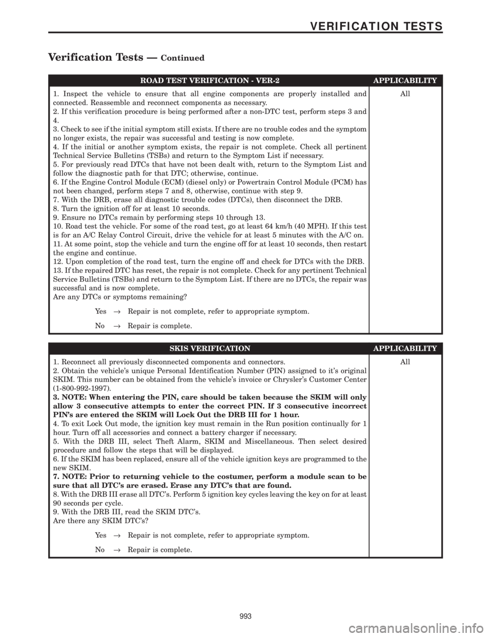
ROAD TEST VERIFICATION - VER-2 APPLICABILITY
1. Inspect the vehicle to ensure that all engine components are properly installed and
connected. Reassemble and reconnect components as necessary.
2. If this verification procedure is being performed after a non-DTC test, perform steps 3 and
4.
3. Check to see if the initial symptom still exists. If there are no trouble codes and the symptom
no longer exists, the repair was successful and testing is now complete.
4. If the initial or another symptom exists, the repair is not complete. Check all pertinent
Technical Service Bulletins (TSBs) and return to the Symptom List if necessary.
5. For previously read DTCs that have not been dealt with, return to the Symptom List and
follow the diagnostic path for that DTC; otherwise, continue.
6. If the Engine Control Module (ECM) (diesel only) or Powertrain Control Module (PCM) has
not been changed, perform steps 7 and 8, otherwise, continue with step 9.
7. With the DRB, erase all diagnostic trouble codes (DTCs), then disconnect the DRB.
8. Turn the ignition off for at least 10 seconds.
9. Ensure no DTCs remain by performing steps 10 through 13.
10. Road test the vehicle. For some of the road test, go at least 64 km/h (40 MPH). If this test
is for an A/C Relay Control Circuit, drive the vehicle for at least 5 minutes with the A/C on.
11. At some point, stop the vehicle and turn the engine off for at least 10 seconds, then restart
the engine and continue.
12. Upon completion of the road test, turn the engine off and check for DTCs with the DRB.
13. If the repaired DTC has reset, the repair is not complete. Check for any pertinent Technical
Service Bulletins (TSBs) and return to the Symptom List. If there are no DTCs, the repair was
successful and is now complete.
Are any DTCs or symptoms remaining?All
Ye s®Repair is not complete, refer to appropriate symptom.
No®Repair is complete.
SKIS VERIFICATION APPLICABILITY
1. Reconnect all previously disconnected components and connectors.
2. Obtain the vehicle's unique Personal Identification Number (PIN) assigned to it's original
SKIM. This number can be obtained from the vehicle's invoice or Chrysler's Customer Center
(1-800-992-1997).
3. NOTE: When entering the PIN, care should be taken because the SKIM will only
allow 3 consecutive attempts to enter the correct PIN. If 3 consecutive incorrect
PIN's are entered the SKIM will Lock Out the DRB III for 1 hour.
4. To exit Lock Out mode, the ignition key must remain in the Run position continually for 1
hour. Turn off all accessories and connect a battery charger if necessary.
5. With the DRB III, select Theft Alarm, SKIM and Miscellaneous. Then select desired
procedure and follow the steps that will be displayed.
6. If the SKIM has been replaced, ensure all of the vehicle ignition keys are programmed to the
new SKIM.
7. NOTE: Prior to returning vehicle to the costumer, perform a module scan to be
sure that all DTC's are erased. Erase any DTC's that are found.
8. With the DRB III erase all DTC's. Perform 5 ignition key cycles leaving the key on for at least
90 seconds per cycle.
9. With the DRB III, read the SKIM DTC's.
Are there any SKIM DTC's?All
Ye s®Repair is not complete, refer to appropriate symptom.
No®Repair is complete.
993
VERIFICATION TESTS
Verification Tests ÐContinued
Page 1174 of 4284
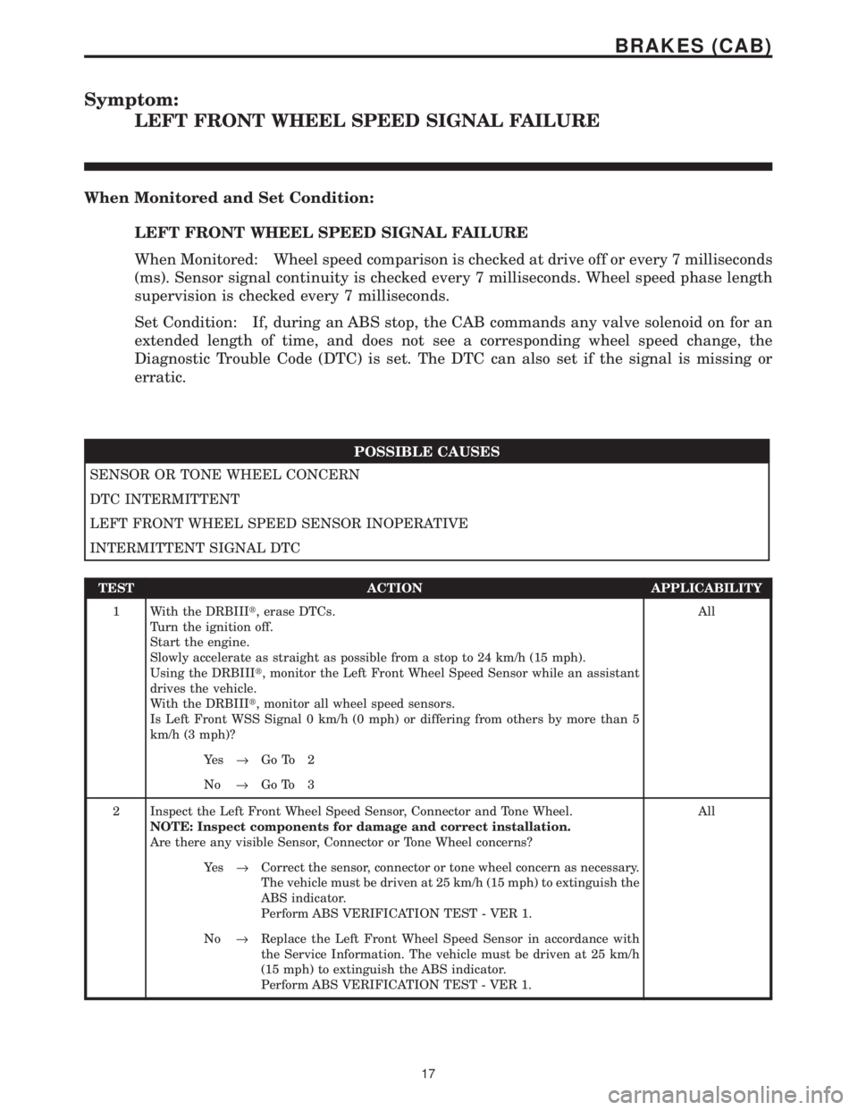
Symptom:
LEFT FRONT WHEEL SPEED SIGNAL FAILURE
When Monitored and Set Condition:
LEFT FRONT WHEEL SPEED SIGNAL FAILURE
When Monitored: Wheel speed comparison is checked at drive off or every 7 milliseconds
(ms). Sensor signal continuity is checked every 7 milliseconds. Wheel speed phase length
supervision is checked every 7 milliseconds.
Set Condition: If, during an ABS stop, the CAB commands any valve solenoid on for an
extended length of time, and does not see a corresponding wheel speed change, the
Diagnostic Trouble Code (DTC) is set. The DTC can also set if the signal is missing or
erratic.
POSSIBLE CAUSES
SENSOR OR TONE WHEEL CONCERN
DTC INTERMITTENT
LEFT FRONT WHEEL SPEED SENSOR INOPERATIVE
INTERMITTENT SIGNAL DTC
TEST ACTION APPLICABILITY
1 With the DRBIIIt, erase DTCs.
Turn the ignition off.
Start the engine.
Slowly accelerate as straight as possible from a stop to 24 km/h (15 mph).
Using the DRBIIIt, monitor the Left Front Wheel Speed Sensor while an assistant
drives the vehicle.
With the DRBIIIt, monitor all wheel speed sensors.
Is Left Front WSS Signal 0 km/h (0 mph) or differing from others by more than 5
km/h (3 mph)?All
Ye s®Go To 2
No®Go To 3
2 Inspect the Left Front Wheel Speed Sensor, Connector and Tone Wheel.
NOTE: Inspect components for damage and correct installation.
Are there any visible Sensor, Connector or Tone Wheel concerns?All
Ye s®Correct the sensor, connector or tone wheel concern as necessary.
The vehicle must be driven at 25 km/h (15 mph) to extinguish the
ABS indicator.
Perform ABS VERIFICATION TEST - VER 1.
No®Replace the Left Front Wheel Speed Sensor in accordance with
the Service Information. The vehicle must be driven at 25 km/h
(15 mph) to extinguish the ABS indicator.
Perform ABS VERIFICATION TEST - VER 1.
17
BRAKES (CAB)
Page 1176 of 4284
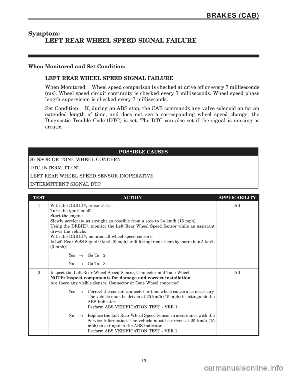
Symptom:
LEFT REAR WHEEL SPEED SIGNAL FAILURE
When Monitored and Set Condition:
LEFT REAR WHEEL SPEED SIGNAL FAILURE
When Monitored: Wheel speed comparison is checked at drive off or every 7 milliseconds
(ms). Wheel speed circuit continuity is checked every 7 milliseconds. Wheel speed phase
length supervision is checked every 7 milliseconds.
Set Condition: If, during an ABS stop, the CAB commands any valve solenoid on for an
extended length of time, and does not see a corresponding wheel speed change, the
Diagnostic Trouble Code (DTC) is set. The DTC can also set if the signal is missing or
erratic.
POSSIBLE CAUSES
SENSOR OR TONE WHEEL CONCERN
DTC INTERMITTENT
LEFT REAR WHEEL SPEED SENSOR INOPERATIVE
INTERMITTENT SIGNAL DTC
TEST ACTION APPLICABILITY
1 With the DRBIIIt, erase DTCs.
Turn the ignition off.
Start the engine.
Slowly accelerate as straight as possible from a stop to 24 km/h (15 mph).
Using the DRBIIIt, monitor the Left Rear Wheel Speed Sensor while an assistant
drives the vehicle.
With the DRBIIIt, monitor all wheel speed sensors.
Is Left Rear WSS Signal 0 km/h (0 mph) or differing from others by more than 5 km/h
(3 mph)?All
Ye s®Go To 2
No®Go To 3
2 Inspect the Left Rear Wheel Speed Sensor, Connector and Tone Wheel.
NOTE: Inspect components for damage and correct installation.
Are there any visible Sensor, Connector or Tone Wheel concerns?All
Ye s®Correct the sensor, connector or tone wheel concern as necessary.
The vehicle must be driven at 25 km/h (15 mph) to extinguish the
ABS indicator.
Perform ABS VERIFICATION TEST - VER 1.
No®Replace the Left Rear Wheel Speed Sensor in accordance with the
Service Information. The vehicle must be driven at 25 km/h (15
mph) to extinguish the ABS indicator.
Perform ABS VERIFICATION TEST - VER 1.
19
BRAKES (CAB)
Page 1181 of 4284
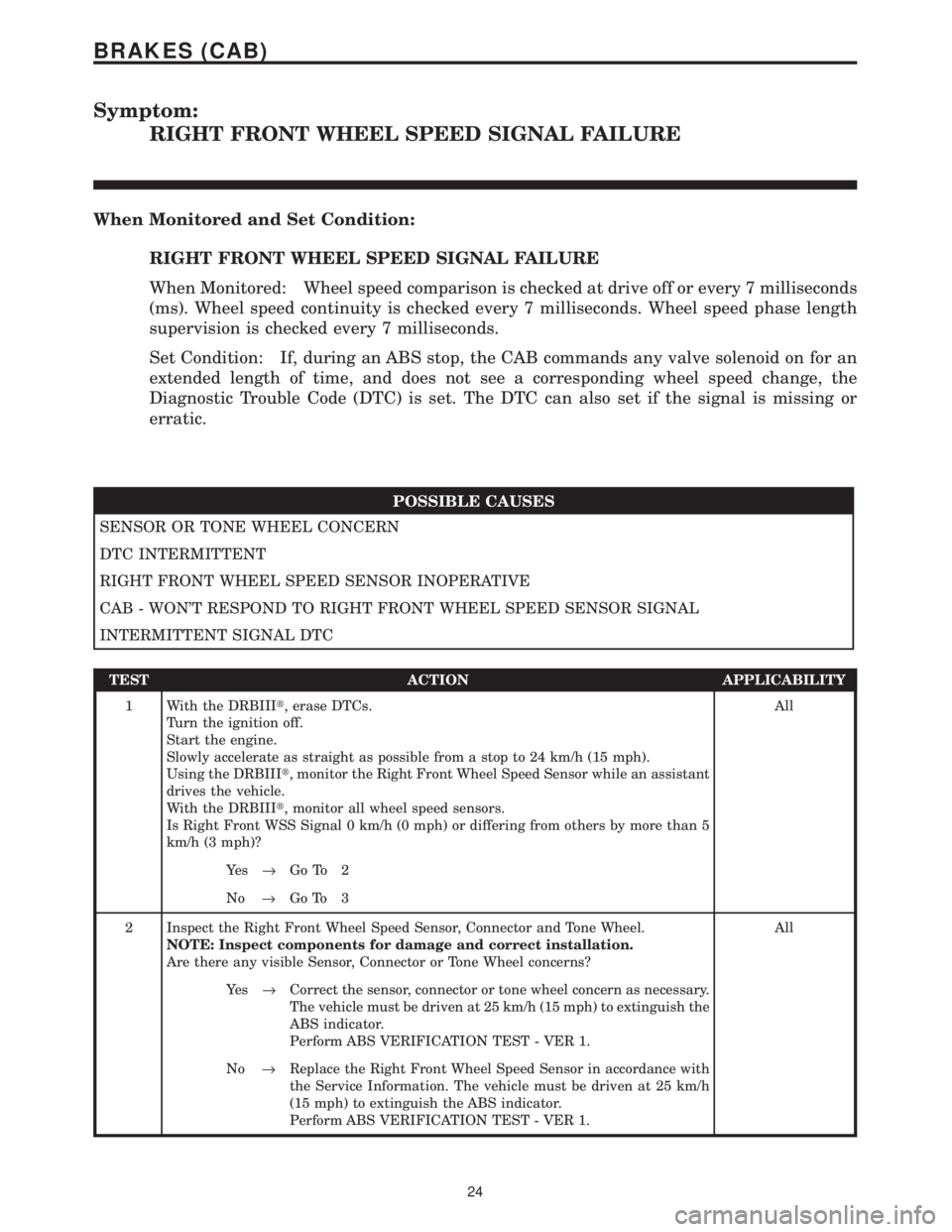
Symptom:
RIGHT FRONT WHEEL SPEED SIGNAL FAILURE
When Monitored and Set Condition:
RIGHT FRONT WHEEL SPEED SIGNAL FAILURE
When Monitored: Wheel speed comparison is checked at drive off or every 7 milliseconds
(ms). Wheel speed continuity is checked every 7 milliseconds. Wheel speed phase length
supervision is checked every 7 milliseconds.
Set Condition: If, during an ABS stop, the CAB commands any valve solenoid on for an
extended length of time, and does not see a corresponding wheel speed change, the
Diagnostic Trouble Code (DTC) is set. The DTC can also set if the signal is missing or
erratic.
POSSIBLE CAUSES
SENSOR OR TONE WHEEL CONCERN
DTC INTERMITTENT
RIGHT FRONT WHEEL SPEED SENSOR INOPERATIVE
CAB - WON'T RESPOND TO RIGHT FRONT WHEEL SPEED SENSOR SIGNAL
INTERMITTENT SIGNAL DTC
TEST ACTION APPLICABILITY
1 With the DRBIIIt, erase DTCs.
Turn the ignition off.
Start the engine.
Slowly accelerate as straight as possible from a stop to 24 km/h (15 mph).
Using the DRBIIIt, monitor the Right Front Wheel Speed Sensor while an assistant
drives the vehicle.
With the DRBIIIt, monitor all wheel speed sensors.
Is Right Front WSS Signal 0 km/h (0 mph) or differing from others by more than 5
km/h (3 mph)?All
Ye s®Go To 2
No®Go To 3
2 Inspect the Right Front Wheel Speed Sensor, Connector and Tone Wheel.
NOTE: Inspect components for damage and correct installation.
Are there any visible Sensor, Connector or Tone Wheel concerns?All
Ye s®Correct the sensor, connector or tone wheel concern as necessary.
The vehicle must be driven at 25 km/h (15 mph) to extinguish the
ABS indicator.
Perform ABS VERIFICATION TEST - VER 1.
No®Replace the Right Front Wheel Speed Sensor in accordance with
the Service Information. The vehicle must be driven at 25 km/h
(15 mph) to extinguish the ABS indicator.
Perform ABS VERIFICATION TEST - VER 1.
24
BRAKES (CAB)
Page 1183 of 4284
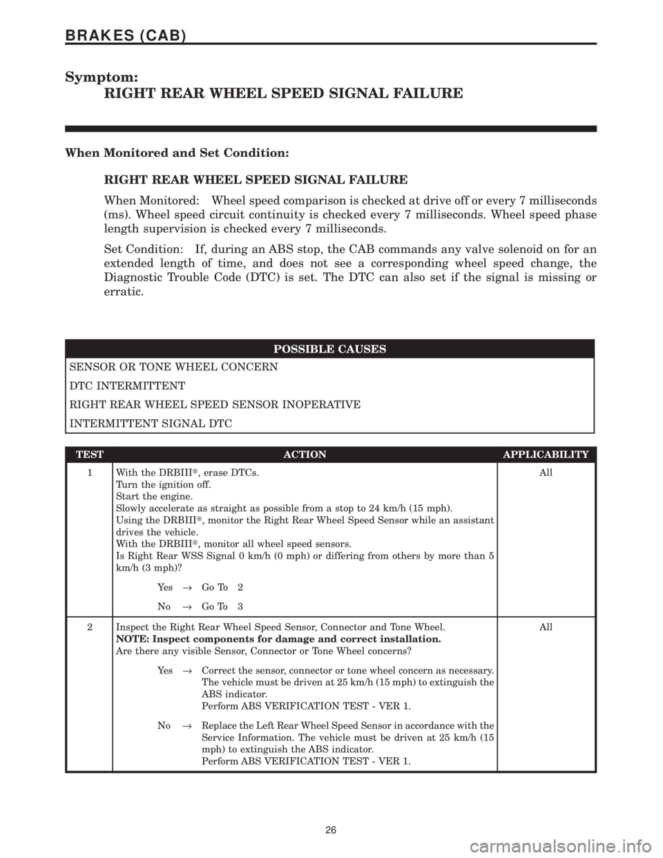
Symptom:
RIGHT REAR WHEEL SPEED SIGNAL FAILURE
When Monitored and Set Condition:
RIGHT REAR WHEEL SPEED SIGNAL FAILURE
When Monitored: Wheel speed comparison is checked at drive off or every 7 milliseconds
(ms). Wheel speed circuit continuity is checked every 7 milliseconds. Wheel speed phase
length supervision is checked every 7 milliseconds.
Set Condition: If, during an ABS stop, the CAB commands any valve solenoid on for an
extended length of time, and does not see a corresponding wheel speed change, the
Diagnostic Trouble Code (DTC) is set. The DTC can also set if the signal is missing or
erratic.
POSSIBLE CAUSES
SENSOR OR TONE WHEEL CONCERN
DTC INTERMITTENT
RIGHT REAR WHEEL SPEED SENSOR INOPERATIVE
INTERMITTENT SIGNAL DTC
TEST ACTION APPLICABILITY
1 With the DRBIIIt, erase DTCs.
Turn the ignition off.
Start the engine.
Slowly accelerate as straight as possible from a stop to 24 km/h (15 mph).
Using the DRBIIIt, monitor the Right Rear Wheel Speed Sensor while an assistant
drives the vehicle.
With the DRBIIIt, monitor all wheel speed sensors.
Is Right Rear WSS Signal 0 km/h (0 mph) or differing from others by more than 5
km/h (3 mph)?All
Ye s®Go To 2
No®Go To 3
2 Inspect the Right Rear Wheel Speed Sensor, Connector and Tone Wheel.
NOTE: Inspect components for damage and correct installation.
Are there any visible Sensor, Connector or Tone Wheel concerns?All
Ye s®Correct the sensor, connector or tone wheel concern as necessary.
The vehicle must be driven at 25 km/h (15 mph) to extinguish the
ABS indicator.
Perform ABS VERIFICATION TEST - VER 1.
No®Replace the Left Rear Wheel Speed Sensor in accordance with the
Service Information. The vehicle must be driven at 25 km/h (15
mph) to extinguish the ABS indicator.
Perform ABS VERIFICATION TEST - VER 1.
26
BRAKES (CAB)
Page 1186 of 4284
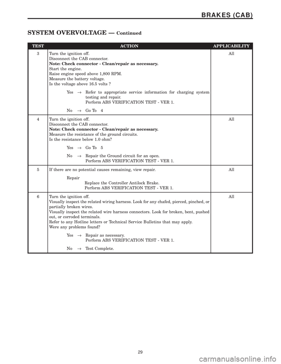
TEST ACTION APPLICABILITY
3 Turn the ignition off.
Disconnect the CAB connector.
Note: Check connector - Clean/repair as necessary.
Start the engine.
Raise engine speed above 1,800 RPM.
Measure the battery voltage.
Is the voltage above 16.5 volts ?All
Ye s®Refer to appropriate service information for charging system
testing and repair.
Perform ABS VERIFICATION TEST - VER 1.
No®Go To 4
4 Turn the ignition off.
Disconnect the CAB connector.
Note: Check connector - Clean/repair as necessary.
Measure the resistance of the ground circuits.
Is the resistance below 1.0 ohm?All
Ye s®Go To 5
No®Repair the Ground circuit for an open.
Perform ABS VERIFICATION TEST - VER 1.
5 If there are no potential causes remaining, view repair. All
Repair
Replace the Controller Antilock Brake.
Perform ABS VERIFICATION TEST - VER 1.
6 Turn the ignition off.
Visually inspect the related wiring harness. Look for any chafed, pierced, pinched, or
partially broken wires.
Visually inspect the related wire harness connectors. Look for broken, bent, pushed
out, or corroded terminals.
Refer to any Hotline letters or Technical Service Bulletins that may apply.
Were any problems found?All
Ye s®Repair as necessary.
Perform ABS VERIFICATION TEST - VER 1.
No®Test Complete.
29
BRAKES (CAB)
SYSTEM OVERVOLTAGE ÐContinued
Page 1215 of 4284
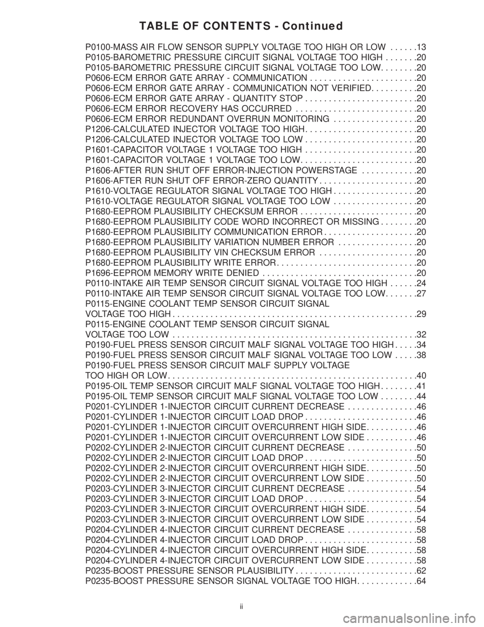
TABLE OF CONTENTS - Continued
P0100-MASS AIR FLOW SENSOR SUPPLY VOLTAGE TOO HIGH OR LOW......13
P0105-BAROMETRIC PRESSURE CIRCUIT SIGNAL VOLTAGE TOO HIGH.......20
P0105-BAROMETRIC PRESSURE CIRCUIT SIGNAL VOLTAGE TOO LOW........20
P0606-ECM ERROR GATE ARRAY - COMMUNICATION.......................20
P0606-ECM ERROR GATE ARRAY - COMMUNICATION NOT VERIFIED..........20
P0606-ECM ERROR GATE ARRAY - QUANTITY STOP........................20
P0606-ECM ERROR RECOVERY HAS OCCURRED..........................20
P0606-ECM ERROR REDUNDANT OVERRUN MONITORING..................20
P1206-CALCULATED INJECTOR VOLTAGE TOO HIGH........................20
P1206-CALCULATED INJECTOR VOLTAGE TOO LOW........................20
P1601-CAPACITOR VOLTAGE 1 VOLTAGE TOO HIGH........................20
P1601-CAPACITOR VOLTAGE 1 VOLTAGE TOO LOW.........................20
P1606-AFTER RUN SHUT OFF ERROR-INJECTION POWERSTAGE............20
P1606-AFTER RUN SHUT OFF ERROR-ZERO QUANTITY.....................20
P1610-VOLTAGE REGULATOR SIGNAL VOLTAGE TOO HIGH..................20
P1610-VOLTAGE REGULATOR SIGNAL VOLTAGE TOO LOW..................20
P1680-EEPROM PLAUSIBILITY CHECKSUM ERROR.........................20
P1680-EEPROM PLAUSIBILITY CODE WORD INCORRECT OR MISSING........20
P1680-EEPROM PLAUSIBILITY COMMUNICATION ERROR....................20
P1680-EEPROM PLAUSIBILITY VARIATION NUMBER ERROR.................20
P1680-EEPROM PLAUSIBILITY VIN CHECKSUM ERROR.....................20
P1680-EEPROM PLAUSIBILITY WRITE ERROR..............................20
P1696-EEPROM MEMORY WRITE DENIED.................................20
P0110-INTAKE AIR TEMP SENSOR CIRCUIT SIGNAL VOLTAGE TOO HIGH......24
P0110-INTAKE AIR TEMP SENSOR CIRCUIT SIGNAL VOLTAGE TOO LOW.......27
P0115-ENGINE COOLANT TEMP SENSOR CIRCUIT SIGNAL
VOLTAGE TOO HIGH....................................................29
P0115-ENGINE COOLANT TEMP SENSOR CIRCUIT SIGNAL
VOLTAGETOO LOW ....................................................32
P0190-FUEL PRESS SENSOR CIRCUIT MALF SIGNAL VOLTAGE TOO HIGH.....34
P0190-FUEL PRESS SENSOR CIRCUIT MALF SIGNAL VOLTAGE TOO LOW.....38
P0190-FUEL PRESS SENSOR CIRCUIT MALF SUPPLY VOLTAGE
TOO HIGH OR LOW.....................................................40
P0195-OIL TEMP SENSOR CIRCUIT MALF SIGNAL VOLTAGE TOO HIGH........41
P0195-OIL TEMP SENSOR CIRCUIT MALF SIGNAL VOLTAGE TOO LOW........44
P0201-CYLINDER 1-INJECTOR CIRCUIT CURRENT DECREASE...............46
P0201-CYLINDER 1-INJECTOR CIRCUIT LOAD DROP........................46
P0201-CYLINDER 1-INJECTOR CIRCUIT OVERCURRENT HIGH SIDE...........46
P0201-CYLINDER 1-INJECTOR CIRCUIT OVERCURRENT LOW SIDE...........46
P0202-CYLINDER 2-INJECTOR CIRCUIT CURRENT DECREASE...............50
P0202-CYLINDER 2-INJECTOR CIRCUIT LOAD DROP........................50
P0202-CYLINDER 2-INJECTOR CIRCUIT OVERCURRENT HIGH SIDE...........50
P0202-CYLINDER 2-INJECTOR CIRCUIT OVERCURRENT LOW SIDE...........50
P0203-CYLINDER 3-INJECTOR CIRCUIT CURRENT DECREASE...............54
P0203-CYLINDER 3-INJECTOR CIRCUIT LOAD DROP........................54
P0203-CYLINDER 3-INJECTOR CIRCUIT OVERCURRENT HIGH SIDE...........54
P0203-CYLINDER 3-INJECTOR CIRCUIT OVERCURRENT LOW SIDE...........54
P0204-CYLINDER 4-INJECTOR CIRCUIT CURRENT DECREASE...............58
P0204-CYLINDER 4-INJECTOR CIRCUIT LOAD DROP........................58
P0204-CYLINDER 4-INJECTOR CIRCUIT OVERCURRENT HIGH SIDE...........58
P0204-CYLINDER 4-INJECTOR CIRCUIT OVERCURRENT LOW SIDE...........58
P0235-BOOST PRESSURE SENSOR PLAUSIBILITY..........................62
P0235-BOOST PRESSURE SENSOR SIGNAL VOLTAGE TOO HIGH.............64
ii