2001 CHRYSLER VOYAGER sensor
[x] Cancel search: sensorPage 3280 of 4284
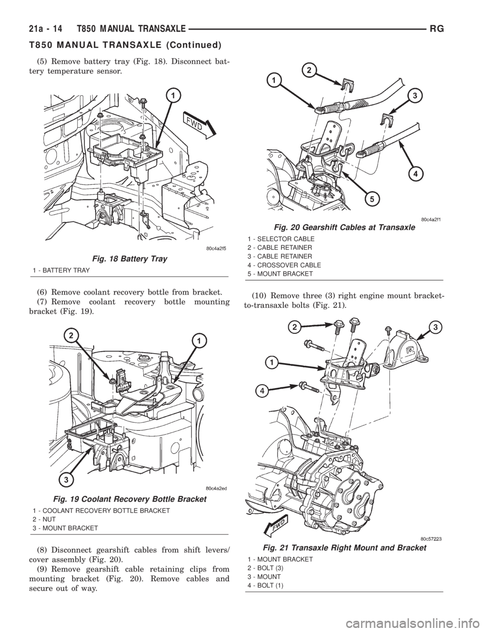
(5) Remove battery tray (Fig. 18). Disconnect bat-
tery temperature sensor.
(6) Remove coolant recovery bottle from bracket.
(7) Remove coolant recovery bottle mounting
bracket (Fig. 19).
(8) Disconnect gearshift cables from shift levers/
cover assembly (Fig. 20).
(9) Remove gearshift cable retaining clips from
mounting bracket (Fig. 20). Remove cables and
secure out of way.(10) Remove three (3) right engine mount bracket-
to-transaxle bolts (Fig. 21).
Fig. 18 Battery Tray
1 - BATTERY TRAY
Fig. 19 Coolant Recovery Bottle Bracket
1 - COOLANT RECOVERY BOTTLE BRACKET
2 - NUT
3 - MOUNT BRACKET
Fig. 20 Gearshift Cables at Transaxle
1 - SELECTOR CABLE
2 - CABLE RETAINER
3 - CABLE RETAINER
4 - CROSSOVER CABLE
5 - MOUNT BRACKET
Fig. 21 Transaxle Right Mount and Bracket
1 - MOUNT BRACKET
2 - BOLT (3)
3 - MOUNT
4 - BOLT (1)
21a - 14 T850 MANUAL TRANSAXLERG
T850 MANUAL TRANSAXLE (Continued)
Page 3302 of 4284
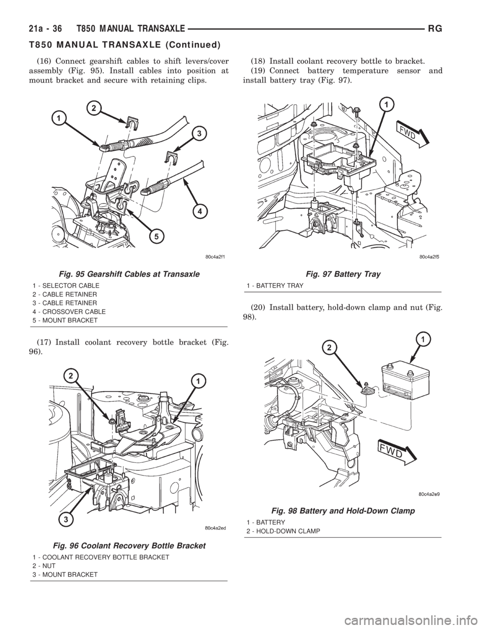
(16) Connect gearshift cables to shift levers/cover
assembly (Fig. 95). Install cables into position at
mount bracket and secure with retaining clips.
(17) Install coolant recovery bottle bracket (Fig.
96).(18) Install coolant recovery bottle to bracket.
(19) Connect battery temperature sensor and
install battery tray (Fig. 97).
(20) Install battery, hold-down clamp and nut (Fig.
98).
Fig. 95 Gearshift Cables at Transaxle
1 - SELECTOR CABLE
2 - CABLE RETAINER
3 - CABLE RETAINER
4 - CROSSOVER CABLE
5 - MOUNT BRACKET
Fig. 96 Coolant Recovery Bottle Bracket
1 - COOLANT RECOVERY BOTTLE BRACKET
2 - NUT
3 - MOUNT BRACKET
Fig. 97 Battery Tray
1 - BATTERY TRAY
Fig. 98 Battery and Hold-Down Clamp
1 - BATTERY
2 - HOLD-DOWN CLAMP
21a - 36 T850 MANUAL TRANSAXLERG
T850 MANUAL TRANSAXLE (Continued)
Page 3321 of 4284
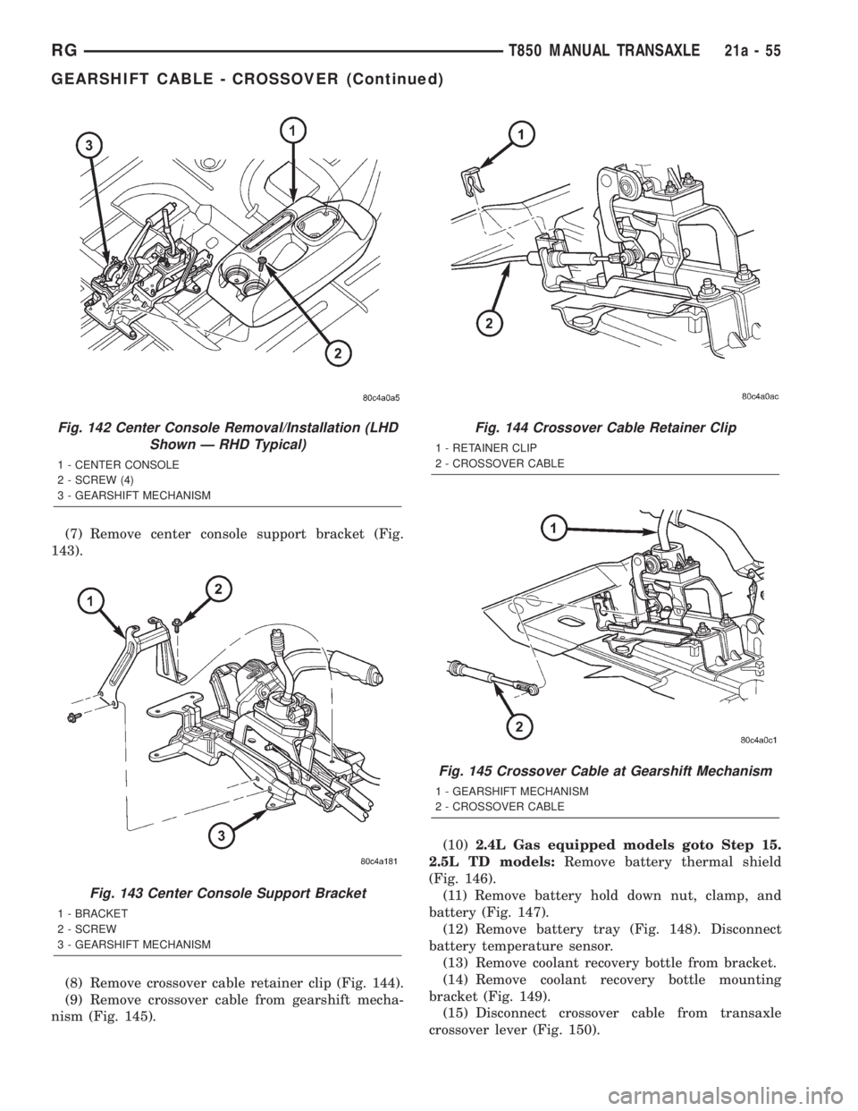
(7) Remove center console support bracket (Fig.
143).
(8) Remove crossover cable retainer clip (Fig. 144).
(9) Remove crossover cable from gearshift mecha-
nism (Fig. 145).(10)2.4L Gas equipped models goto Step 15.
2.5L TD models:Remove battery thermal shield
(Fig. 146).
(11) Remove battery hold down nut, clamp, and
battery (Fig. 147).
(12) Remove battery tray (Fig. 148). Disconnect
battery temperature sensor.
(13) Remove coolant recovery bottle from bracket.
(14) Remove coolant recovery bottle mounting
bracket (Fig. 149).
(15) Disconnect crossover cable from transaxle
crossover lever (Fig. 150).
Fig. 142 Center Console Removal/Installation (LHD
Shown Ð RHD Typical)
1 - CENTER CONSOLE
2 - SCREW (4)
3 - GEARSHIFT MECHANISM
Fig. 143 Center Console Support Bracket
1 - BRACKET
2 - SCREW
3 - GEARSHIFT MECHANISM
Fig. 144 Crossover Cable Retainer Clip
1 - RETAINER CLIP
2 - CROSSOVER CABLE
Fig. 145 Crossover Cable at Gearshift Mechanism
1 - GEARSHIFT MECHANISM
2 - CROSSOVER CABLE
RGT850 MANUAL TRANSAXLE21a-55
GEARSHIFT CABLE - CROSSOVER (Continued)
Page 3323 of 4284
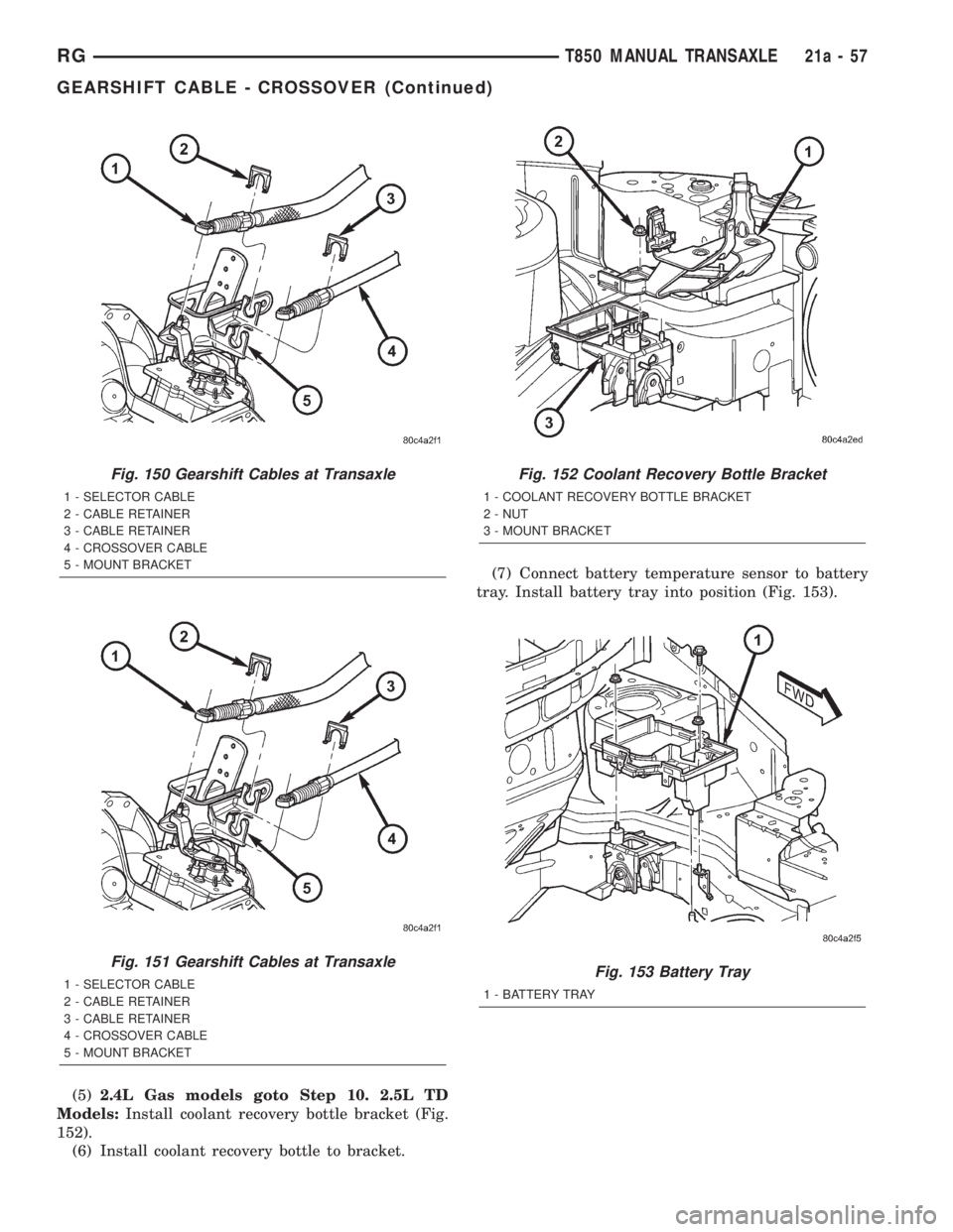
(5)2.4L Gas models goto Step 10. 2.5L TD
Models:Install coolant recovery bottle bracket (Fig.
152).
(6) Install coolant recovery bottle to bracket.(7) Connect battery temperature sensor to battery
tray. Install battery tray into position (Fig. 153).
Fig. 150 Gearshift Cables at Transaxle
1 - SELECTOR CABLE
2 - CABLE RETAINER
3 - CABLE RETAINER
4 - CROSSOVER CABLE
5 - MOUNT BRACKET
Fig. 151 Gearshift Cables at Transaxle
1 - SELECTOR CABLE
2 - CABLE RETAINER
3 - CABLE RETAINER
4 - CROSSOVER CABLE
5 - MOUNT BRACKET
Fig. 152 Coolant Recovery Bottle Bracket
1 - COOLANT RECOVERY BOTTLE BRACKET
2 - NUT
3 - MOUNT BRACKET
Fig. 153 Battery Tray
1 - BATTERY TRAY
RGT850 MANUAL TRANSAXLE21a-57
GEARSHIFT CABLE - CROSSOVER (Continued)
Page 3329 of 4284
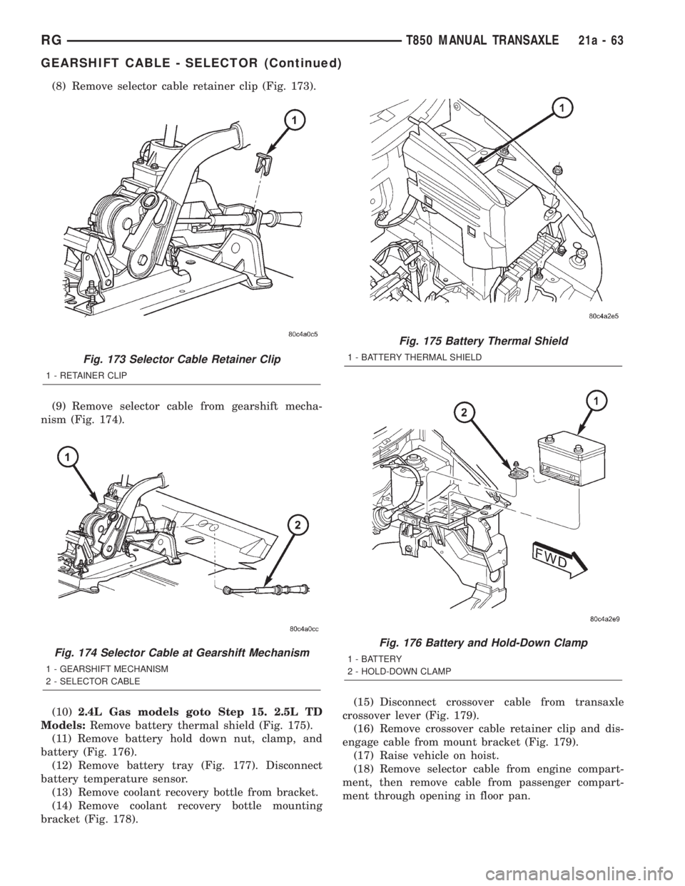
(8) Remove selector cable retainer clip (Fig. 173).
(9) Remove selector cable from gearshift mecha-
nism (Fig. 174).
(10)2.4L Gas models goto Step 15. 2.5L TD
Models:Remove battery thermal shield (Fig. 175).
(11) Remove battery hold down nut, clamp, and
battery (Fig. 176).
(12) Remove battery tray (Fig. 177). Disconnect
battery temperature sensor.
(13) Remove coolant recovery bottle from bracket.
(14) Remove coolant recovery bottle mounting
bracket (Fig. 178).(15) Disconnect crossover cable from transaxle
crossover lever (Fig. 179).
(16) Remove crossover cable retainer clip and dis-
engage cable from mount bracket (Fig. 179).
(17) Raise vehicle on hoist.
(18) Remove selector cable from engine compart-
ment, then remove cable from passenger compart-
ment through opening in floor pan.
Fig. 173 Selector Cable Retainer Clip
1 - RETAINER CLIP
Fig. 174 Selector Cable at Gearshift Mechanism
1 - GEARSHIFT MECHANISM
2 - SELECTOR CABLE
Fig. 175 Battery Thermal Shield
1 - BATTERY THERMAL SHIELD
Fig. 176 Battery and Hold-Down Clamp
1 - BATTERY
2 - HOLD-DOWN CLAMP
RGT850 MANUAL TRANSAXLE21a-63
GEARSHIFT CABLE - SELECTOR (Continued)
Page 3331 of 4284
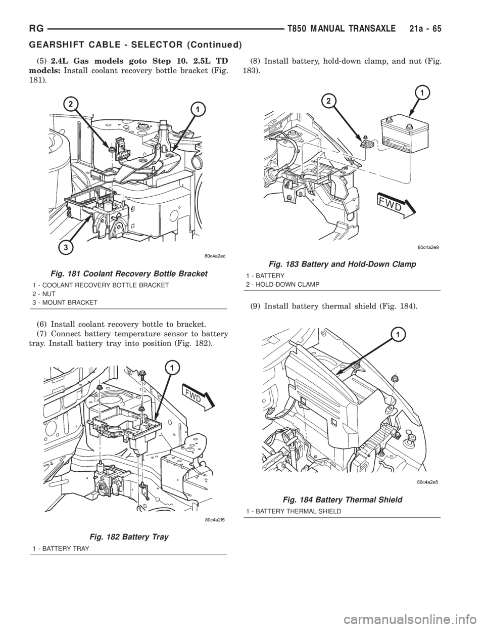
(5)2.4L Gas models goto Step 10. 2.5L TD
models:Install coolant recovery bottle bracket (Fig.
181).
(6) Install coolant recovery bottle to bracket.
(7) Connect battery temperature sensor to battery
tray. Install battery tray into position (Fig. 182).(8) Install battery, hold-down clamp, and nut (Fig.
183).
(9) Install battery thermal shield (Fig. 184).
Fig. 181 Coolant Recovery Bottle Bracket
1 - COOLANT RECOVERY BOTTLE BRACKET
2 - NUT
3 - MOUNT BRACKET
Fig. 182 Battery Tray
1 - BATTERY TRAY
Fig. 183 Battery and Hold-Down Clamp
1 - BATTERY
2 - HOLD-DOWN CLAMP
Fig. 184 Battery Thermal Shield
1 - BATTERY THERMAL SHIELD
RGT850 MANUAL TRANSAXLE21a-65
GEARSHIFT CABLE - SELECTOR (Continued)
Page 3362 of 4284
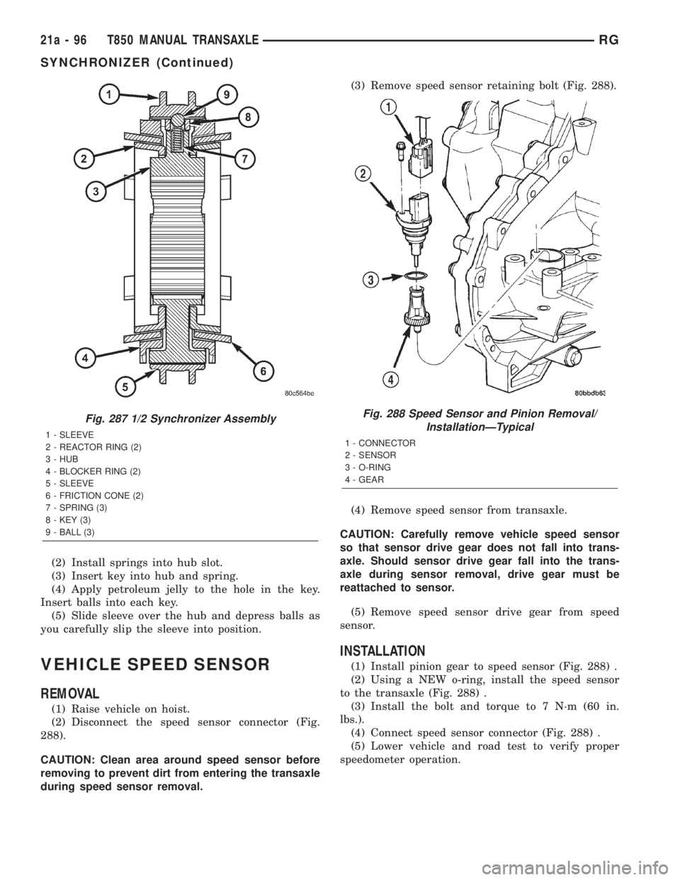
(2) Install springs into hub slot.
(3) Insert key into hub and spring.
(4) Apply petroleum jelly to the hole in the key.
Insert balls into each key.
(5) Slide sleeve over the hub and depress balls as
you carefully slip the sleeve into position.
VEHICLE SPEED SENSOR
REMOVAL
(1) Raise vehicle on hoist.
(2) Disconnect the speed sensor connector (Fig.
288).
CAUTION: Clean area around speed sensor before
removing to prevent dirt from entering the transaxle
during speed sensor removal.(3) Remove speed sensor retaining bolt (Fig. 288).
(4) Remove speed sensor from transaxle.
CAUTION: Carefully remove vehicle speed sensor
so that sensor drive gear does not fall into trans-
axle. Should sensor drive gear fall into the trans-
axle during sensor removal, drive gear must be
reattached to sensor.
(5) Remove speed sensor drive gear from speed
sensor.
INSTALLATION
(1) Install pinion gear to speed sensor (Fig. 288) .
(2) Using a NEW o-ring, install the speed sensor
to the transaxle (Fig. 288) .
(3) Install the bolt and torque to 7 N´m (60 in.
lbs.).
(4) Connect speed sensor connector (Fig. 288) .
(5) Lower vehicle and road test to verify proper
speedometer operation.
Fig. 287 1/2 Synchronizer Assembly
1 - SLEEVE
2 - REACTOR RING (2)
3 - HUB
4 - BLOCKER RING (2)
5 - SLEEVE
6 - FRICTION CONE (2)
7 - SPRING (3)
8 - KEY (3)
9 - BALL (3)
Fig. 288 Speed Sensor and Pinion Removal/
InstallationÐTypical
1 - CONNECTOR
2 - SENSOR
3 - O-RING
4 - GEAR
21a - 96 T850 MANUAL TRANSAXLERG
SYNCHRONIZER (Continued)
Page 3632 of 4284
²an air conditioning button that allows the com-
pressor to be turned on/off. The Snowflake button
contains an LED that illuminates to shown when the
function is in operation.
²rotary knobs for front and rear fan speed selec-
tion.
²a rotary knob for mode control.
REAR CONTROL PANEL
A rear control panel centrally mounted on the
headliner has a rotary adjustment for temperature
and fan speed control of the rear unit by intermedi-
ate seat passengers when the front control rear knob
is set to the rear position.
DESCRIPTION - THREE ZONE Automatic
Temperature Control
The Three-Zone Automatic Temperature Control
(ATC) allows occupants to select a comfort tempera-
ture, which is the perceived temperature level not
the actual passenger compartment air temperature.
The Three Zone Automatic Temperature Control
system includes a dust and odor air filter. The filter
element is the same size as the air conditioning evap-
orator to ensure ample capacity. A door at the base of
the heater and air conditioning housing below the
glove box provides easy access to the filter element.
The ATC computer utilizes integrated circuitry and
information carried on the Programmable Communi-
cations Interface (PCI) data bus network to monitor
many sensors and switch inputs throughout the vehi-
cle. In response to those inputs, the internal circuitry
and programming of the ATC computer allow it to
control electronic functions and features of the ATC
system. The inputs to the ATC computer are:
²Vehicle Speed/Engine RPM± The ATC com-
puter monitors engine RPM, vehicle speed and Man-
ifold Absolute Pressure information from the PCM.
²Coolant Temperature± ATC computer moni-
tors Coolant temperature received from the PCM and
converts it to degrees Fahrenheit.
²Ambient Temperature± ATC computer moni-
tors Ambient temperature from the Compass Mini
Trip Computer (CMTC) and converts it to degrees
Fahrenheit.
²Engine Miscellaneous Sensor Status±ATC
computer monitors A/C disable information from the
PCM.
²Refrigerant Pressure± ATC computer moni-
tors Barometric Pressure, Intake Air Temperature,
High Side Pressure and Methanol Content as broad-
cast by the PCM.
²Door Ajar Status± The ATC computer moni-
tors Driver Front Door, Passenger Front Door, Left
Rear Door, Right Rear Door and Liftgate ajar infor-
mation, as identified by the Body Control Module(BCM), to determine if all in-car temperatures should
be maintained.
²Dimming± The ATC computer monitors dim-
ming status from the BCM to determine the required
level of brightness and will dim accordingly.
²Vehicle Odometer± The ATC computer moni-
tors the vehicle odometer information from the BCM
to prevent flashing the VF tube icons if the manual
motor calibration or manual cooldown tests have
failed. Flashing of the display icons will cease when
the vehicle odometer is greater than 3 miles.
²English Metric± The ATC computer monitors
the English/Metric information broadcast by the
CMTC. The set temp displays for both the front and
rear control heads will be set accordingly.
²Vehicle Identification Number± The ATC
computer monitors the last eight characters of the
VIN broadcast by the PCM and compares it to the
information stored in EEPROM. If it is different, the
new number will be stored over the old one and a
motor calibration shall be initiated.
²A/C System Information± The ATC computer
will send a message for Evaporator Temperature too
Low, Fan Blower Relay status, Evaporator Sensor
Failure, Rear Window Defogger Relay and A/C Select.
FRONT CONTROL PANEL
The front control panel and integral computer is
mounted in the instrument panel.
The instrument panel mounted control and inte-
gral computer contains:
²A power button which allows the system to be
completely turned off. The display is blank when the
system is off.
²Three rocker switches that select comfort tem-
peratures from 15É to 30É C (59É to 85É F), which are
shown in the vacuum-fluorescent digital control dis-
play. If the set temp is 59 and the down button is
pressed, the set temp value will become 55 but the
display will show LO. If the set temp is 85 and the
up button is pressed, the set temp value will become
90 but the display will show HIGH. Temperatures
can be displayed in either metric or fahrenheit,
which is controlled from the overhead console.
²A rocker switch that selects a cool-down rate.
LO-AUTO or HI-AUTO are displayed when the sys-
tem is in automatic operation.
²A defroster button which turns on the defroster
independently during full automatic control. A
defroster symbol illuminates in the display when the
button is pressed.
²Air recirculation button. A Recirculation symbol
appears in the display when the button is pressed, or
when the system exceeds 80 percent circulated air
under automatic control due to high air conditioning
demand.
24 - 2 HEATING & AIR CONDITIONINGRS
HEATING & AIR CONDITIONING (Continued)