Page 379 of 4284

Symptom:
IGNITION MUX SWITCH INPUT OPEN
When Monitored and Set Condition:
IGNITION MUX SWITCH INPUT OPEN
When Monitored: With the ignition on and battery voltage greater than 10.4 volts.
Set Condition: The Ignition MUX sense circuit voltage at the BCM goes above 4.9 volts.
POSSIBLE CAUSES
IGNITION SWITCH
IGNITION SWITCH SENSE CIRCUIT OPEN
IGNITION SWITCH SENSE RETURN CIRCUIT OPEN
BODY CONTROL MODULE
BODY CONTROL MODULE
TEST ACTION APPLICABILITY
1 Turn the ignition off.
Disconnect the ignition switch 5-way connector.
Connect a jumper wire between the Ignition Switch Sense circuit and ground.
With the DRBIIItin Sensors, read the IGNITION SW voltage.
Does the DRBIIItdisplay IGNITION SW 0.0 volts?All
Ye s®Go To 2
No®Go To 3
2 Turn the ignition off.
Gain access to the Body Control Module C5 connector.
Backprobe a jumper wire between the Ignition Switch Sense circuit and ground.
With the DRBIIItin Sensors, read the IGNITION SW voltage.
Does the DRBIIItdisplay IGNITION SW 0.0 volts?All
Ye s®Repair the Ignition Switch Sense circuit for an open.
Perform BODY VERIFICATION TEST - VER 1.
No®Replace the Body Control Module.
Perform BODY VERIFICATION TEST - VER 1.
3 Turn the ignition off.
Disconnect the ignition switch connector.
Connect a jumper wire between the Ignition Switch Sense circuit and the Ignition
Switch Sense Return circuit.
With the DRBIIItin Sensors, read the IGNITION SW voltage.
Does the DRBIIItdisplay IGNITION SW 0.0 volts?All
Ye s®Replace the Ignition Switch.
Perform BODY VERIFICATION TEST - VER 1.
No®Go To 4
350
COMMUNICATION
Page 380 of 4284
TEST ACTION APPLICABILITY
4 Turn the ignition off.
Gain access to the Body Control Module C4 connector.
Backprobe a jumper wire between the Ignition Switch Sense Return circuit and
ground.
With the DRBIIItin Sensors, read the IGNITION SW voltage.
Does the DRBIIItdisplay IGNITION SW 0.0 volts?All
Ye s®Repair the Ignition Switch Sense Return circuit for an open.
Perform BODY VERIFICATION TEST - VER 1.
No®Replace the Body Control Module.
Perform BODY VERIFICATION TEST - VER 1.
351
COMMUNICATION
IGNITION MUX SWITCH INPUT OPEN ÐContinued
Page 381 of 4284

Symptom:
IGNITION MUX SWITCH INPUT SHORT
When Monitored and Set Condition:
IGNITION MUX SWITCH INPUT SHORT
When Monitored: With the ignition on and battery voltage greater than 10.4 volts.
Set Condition: The Ignition MUX Sense circuit voltage at the BCM goes below 0.5 volt for
more than 2 seconds.
POSSIBLE CAUSES
IGNITION SWITCH SENSE CIRCUIT SHORTED
IGNITION SWITCH SENSE RETURN CIRCUIT OPEN
IGNITION SWITCH SHORTED
BODY CONTROL MODULE
TEST ACTION APPLICABILITY
1 Turn the ignition off.
Disconnect the ignition switch 5-way connector.
With the DRBIIItin Sensors, read the IGNITION SW voltage.
Does the DRBIIItdisplay IGNITION SW 0.0 volts?All
Ye s®Go To 2
No®Replace the Ignition Switch.
Perform BODY VERIFICATION TEST - VER 1.
2 Turn the ignition off.
Gain access to the Body Control Module.
Disconnect the Body Control Module C5 connector.
Measure the resistance of the Ignition Switch Sense circuit in the BCM C5 connector.
Is the resistance below 5.0 ohms?All
Ye s®Repair the Ignition Switch Sense circuit for a short to ground.
Perform BODY VERIFICATION TEST - VER 1.
No®Go To 3
3 Turn the ignition off.
Gain access to the Body Control Module.
Disconnect the Body Control Module C4 connector.
Measure the resistance of the Ignition Switch Sense Return circuit in the BCM C4
connector.
Is the resistance below 5.0 ohms?All
Ye s®Repair the Ignition Switch Sense Return circuit for an open.
Perform BODY VERIFICATION TEST - VER 1.
No®Replace the Body Control Module.
Perform BODY VERIFICATION TEST - VER 1.
352
COMMUNICATION
Page 472 of 4284

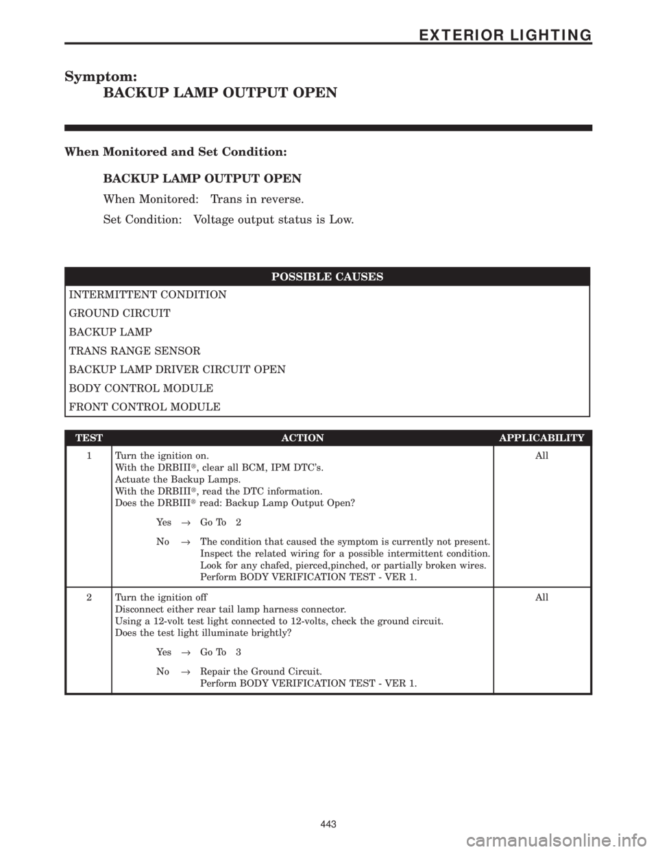
Symptom:
BACKUP LAMP OUTPUT OPEN
When Monitored and Set Condition:
BACKUP LAMP OUTPUT OPEN
When Monitored: Trans in reverse.
Set Condition: Voltage output status is Low.
POSSIBLE CAUSES
INTERMITTENT CONDITION
GROUND CIRCUIT
BACKUP LAMP
TRANS RANGE SENSOR
BACKUP LAMP DRIVER CIRCUIT OPEN
BODY CONTROL MODULE
FRONT CONTROL MODULE
TEST ACTION APPLICABILITY
1 Turn the ignition on.
With the DRBIIIt, clear all BCM, IPM DTC's.
Actuate the Backup Lamps.
With the DRBIIIt, read the DTC information.
Does the DRBIIItread: Backup Lamp Output Open?All
Ye s®Go To 2
No®The condition that caused the symptom is currently not present.
Inspect the related wiring for a possible intermittent condition.
Look for any chafed, pierced,pinched, or partially broken wires.
Perform BODY VERIFICATION TEST - VER 1.
2 Turn the ignition off
Disconnect either rear tail lamp harness connector.
Using a 12-volt test light connected to 12-volts, check the ground circuit.
Does the test light illuminate brightly?All
Ye s®Go To 3
No®Repair the Ground Circuit.
Perform BODY VERIFICATION TEST - VER 1.
443
EXTERIOR LIGHTING
Page 473 of 4284

TEST ACTION APPLICABILITY
3 Turn the ignition off.
Disconnect either rear tail lamp harness connector.
Turn the ignition on.
Engage the transmission to reverse.
Using a 12-volt test light connected to ground, check the Backup Lamps Output
circuit.
Does the test light illuminate brightly?All
Ye s®Replace the applicable Backup Lamp.
Perform BODY VERIFICATION TEST - VER 1.
No®Go To 4
4 Turn the ignition off.
Disconnect the IPM harness connector.
Measure the resistance of the Backup Lamp Output Circuit and ground.
Is the resistance below 5.0 ohms?All
Ye s®Refer to symptom list for problems related to Trans Range Sensor.
Perform BODY VERIFICATION TEST - VER 1.
No®Go To 5
5 Turn the ignition off.
Disconnect the Body Control Module harness connector.
Measure the resistance of the Backup Lamp Driver Circuit to ground.
Is the resistance above 5.0 ohms?All
Ye s®Repair the Backup Lamp Driver Circuit for an open condition.
Perform BODY VERIFICATION TEST - VER 1.
No®Go To 6
6 Turn the ignition off.
Disconnect the Body Control Module harness connector.
Disconnect the FCM from the IPM.
Measure the resistance of the Backup Lamp Driver Circuit and ground.
Is the resistance below 5.0 ohms?All
Ye s®Replace the Body Control Module.
Perform BODY VERIFICATION TEST - VER 1.
No®Replace the Front Control Module.
Perform BODY VERIFICATION TEST - VER 1.
444
EXTERIOR LIGHTING
BACKUP LAMP OUTPUT OPEN ÐContinued
Page 479 of 4284

Symptom:
HEADLAMP SWITCH OPEN
When Monitored and Set Condition:
HEADLAMP SWITCH OPEN
When Monitored: Ignition ON
Set Condition: A Sensor voltage is over 4.8 volts for more than .0625 seconds.
POSSIBLE CAUSES
INTERMITTENT WIRING AND CONNECTORS
HEADLAMP SWITCH MUX CIRCUIT OPEN
HEADLAMP SWITCH MUX RETURN CIRCUIT OPEN
HEADLAMP SWITCH OPEN
BODY CONTROL MODULE
TEST ACTION APPLICABILITY
1 Turn the ignition on.
With the DRBIIIt, record and erase DTC's.
Turn the headlamps to the ON position.
With the DRBIIIt, read DTCs.
Does the DRBIIItdisplay HEADLAMP SWITCH OPEN?All
Ye s®Go To 2
No®Go To 5
2 Turn the ignition off.
Disconnect the Headlamp Switch harness connector.
Connect a jumper wire between the Headlamp Switch MUX circuit and the
Headlamp Switch MUX Return circuit in the Headlamp Switch harness connector.
Turn the ignition on.
With the DRB, select Body, Body Controller and read the Headlamp Switch volts.
Does the DRB Headlamp Switch Sensor voltage read less than 0.5 Volts?All
Ye s®Replace the Headlamp Switch in accordance with the Service
Information.
Perform BODY VERIFICATION TEST - VER 1.
No®Go To 3
450
EXTERIOR LIGHTING
Page 481 of 4284

Symptom:
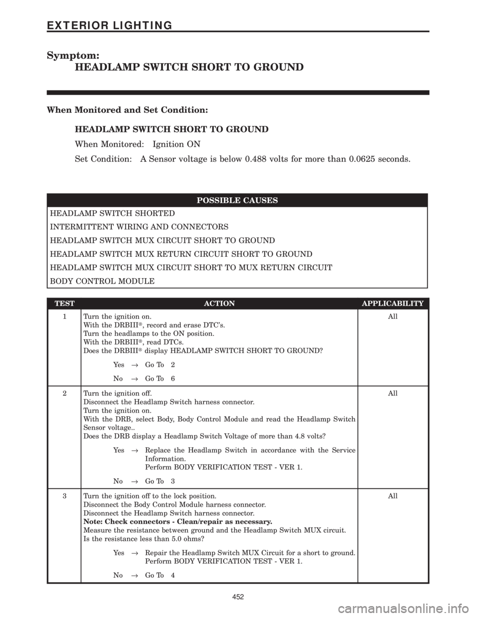
HEADLAMP SWITCH SHORT TO GROUND
When Monitored and Set Condition:
HEADLAMP SWITCH SHORT TO GROUND
When Monitored: Ignition ON
Set Condition: A Sensor voltage is below 0.488 volts for more than 0.0625 seconds.
POSSIBLE CAUSES
HEADLAMP SWITCH SHORTED
INTERMITTENT WIRING AND CONNECTORS
HEADLAMP SWITCH MUX CIRCUIT SHORT TO GROUND
HEADLAMP SWITCH MUX RETURN CIRCUIT SHORT TO GROUND
HEADLAMP SWITCH MUX CIRCUIT SHORT TO MUX RETURN CIRCUIT
BODY CONTROL MODULE
TEST ACTION APPLICABILITY
1 Turn the ignition on.
With the DRBIIIt, record and erase DTC's.
Turn the headlamps to the ON position.
With the DRBIIIt, read DTCs.
Does the DRBIIItdisplay HEADLAMP SWITCH SHORT TO GROUND?All
Ye s®Go To 2
No®Go To 6
2 Turn the ignition off.
Disconnect the Headlamp Switch harness connector.
Turn the ignition on.
With the DRB, select Body, Body Control Module and read the Headlamp Switch
Sensor voltage..
Does the DRB display a Headlamp Switch Voltage of more than 4.8 volts?All
Ye s®Replace the Headlamp Switch in accordance with the Service
Information.
Perform BODY VERIFICATION TEST - VER 1.
No®Go To 3
3 Turn the ignition off to the lock position.
Disconnect the Body Control Module harness connector.
Disconnect the Headlamp Switch harness connector.
Note: Check connectors - Clean/repair as necessary.
Measure the resistance between ground and the Headlamp Switch MUX circuit.
Is the resistance less than 5.0 ohms?All
Ye s®Repair the Headlamp Switch MUX Circuit for a short to ground.
Perform BODY VERIFICATION TEST - VER 1.
No®Go To 4
452
EXTERIOR LIGHTING
Page 543 of 4284

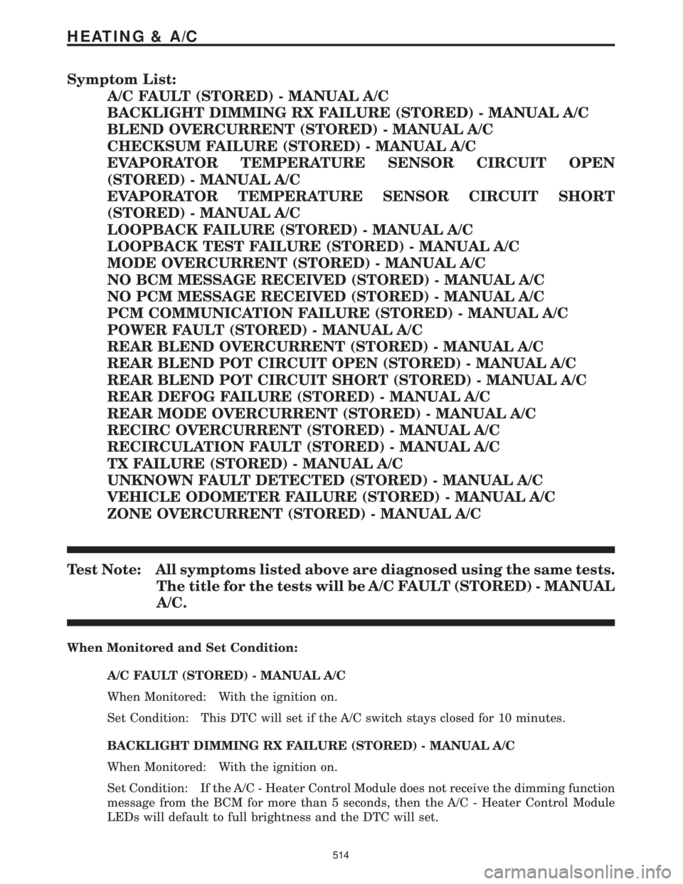
Symptom List:
A/C FAULT (STORED) - MANUAL A/C
BACKLIGHT DIMMING RX FAILURE (STORED) - MANUAL A/C
BLEND OVERCURRENT (STORED) - MANUAL A/C
CHECKSUM FAILURE (STORED) - MANUAL A/C
EVAPORATOR TEMPERATURE SENSOR CIRCUIT OPEN
(STORED) - MANUAL A/C
EVAPORATOR TEMPERATURE SENSOR CIRCUIT SHORT
(STORED) - MANUAL A/C
LOOPBACK FAILURE (STORED) - MANUAL A/C
LOOPBACK TEST FAILURE (STORED) - MANUAL A/C
MODE OVERCURRENT (STORED) - MANUAL A/C
NO BCM MESSAGE RECEIVED (STORED) - MANUAL A/C
NO PCM MESSAGE RECEIVED (STORED) - MANUAL A/C
PCM COMMUNICATION FAILURE (STORED) - MANUAL A/C
POWER FAULT (STORED) - MANUAL A/C
REAR BLEND OVERCURRENT (STORED) - MANUAL A/C
REAR BLEND POT CIRCUIT OPEN (STORED) - MANUAL A/C
REAR BLEND POT CIRCUIT SHORT (STORED) - MANUAL A/C
REAR DEFOG FAILURE (STORED) - MANUAL A/C
REAR MODE OVERCURRENT (STORED) - MANUAL A/C
RECIRC OVERCURRENT (STORED) - MANUAL A/C
RECIRCULATION FAULT (STORED) - MANUAL A/C
TX FAILURE (STORED) - MANUAL A/C
UNKNOWN FAULT DETECTED (STORED) - MANUAL A/C
VEHICLE ODOMETER FAILURE (STORED) - MANUAL A/C
ZONE OVERCURRENT (STORED) - MANUAL A/C
Test Note: All symptoms listed above are diagnosed using the same tests.
The title for the tests will be A/C FAULT (STORED) - MANUAL
A/C.
When Monitored and Set Condition:
A/C FAULT (STORED) - MANUAL A/C
When Monitored: With the ignition on.
Set Condition: This DTC will set if the A/C switch stays closed for 10 minutes.
BACKLIGHT DIMMING RX FAILURE (STORED) - MANUAL A/C
When Monitored: With the ignition on.
Set Condition: If the A/C - Heater Control Module does not receive the dimming function
message from the BCM for more than 5 seconds, then the A/C - Heater Control Module
LEDs will default to full brightness and the DTC will set.
514
HEATING & A/C