2001 CHRYSLER VOYAGER width
[x] Cancel search: widthPage 3669 of 4284
(2) Reconnect the rear HVAC wire harness connec-
tor for the mode door actuator to the actuator connec-
tor receptacle (Fig. 11).
(3) Position the mode door actuator onto the rear
heater-A/C unit housing. If necessary, rotate the
actuator slightly to align the splines on the actuator
output shaft with those in the mode door linkage.
(4) Install and tighten the two screws that secure
the mode door actuator to the rear heater-A/C unit
housing. Tighten the screws to 2 N´m (18 in. lbs.).
(5) Push the top of the rear heater-A/C unit hous-
ing back into position against the right quarter inner
panel.
(6) Install and tighten the screw that secures the
front of the rear heater-A/C unit housing to the right
quarter inner panel. Tighten the screw to 11 N´m (97
in. lbs.).
(7) Install and tighten the screw that secures the
back of the rear heater-A/C unit housing to the right
D-pillar. Tighten the screw to 11 N´m (97 in. lbs.).
(8) Install and tighten the two screws that secure
the top of the quarter trim panel attaching bracket to
the quarter inner panel. Tighten the screws to 1.7
N´m (15 in. lbs.).
(9) Reinstall the right quarter trim panel and
right D-pillar trim panel onto the quarter inner
panel. (Refer to 23 - BODY/INTERIOR/QUARTER
TRIM PANEL - INSTALLATION).
(10) Reconnect the battery negative cable.
(11) Perform the heater-A/C control calibration
procedure. (Refer to 24 - HEATING & AIR CONDI-
TIONING/CONTROLS - FRONT/A/C-HEATER CON-
TROL - STANDARD PROCEDURE - HEATER-A/C
CONTROL CALIBRATION).
POWER MODULE
DESCRIPTION
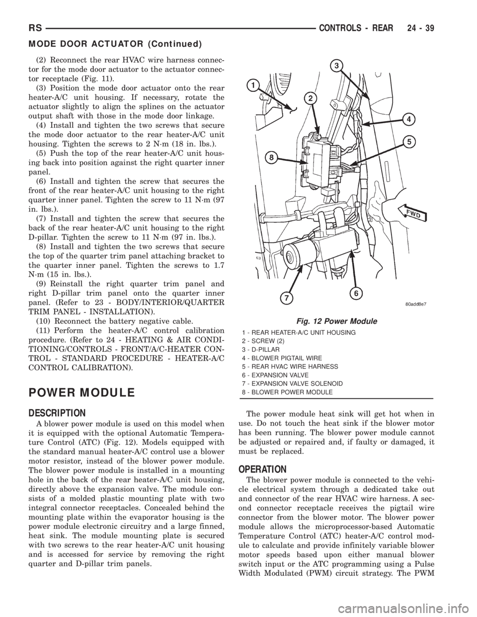
A blower power module is used on this model when
it is equipped with the optional Automatic Tempera-
ture Control (ATC) (Fig. 12). Models equipped with
the standard manual heater-A/C control use a blower
motor resistor, instead of the blower power module.
The blower power module is installed in a mounting
hole in the back of the rear heater-A/C unit housing,
directly above the expansion valve. The module con-
sists of a molded plastic mounting plate with two
integral connector receptacles. Concealed behind the
mounting plate within the evaporator housing is the
power module electronic circuitry and a large finned,
heat sink. The module mounting plate is secured
with two screws to the rear heater-A/C unit housing
and is accessed for service by removing the right
quarter and D-pillar trim panels.The power module heat sink will get hot when in
use. Do not touch the heat sink if the blower motor
has been running. The blower power module cannot
be adjusted or repaired and, if faulty or damaged, it
must be replaced.
OPERATION
The blower power module is connected to the vehi-
cle electrical system through a dedicated take out
and connector of the rear HVAC wire harness. A sec-
ond connector receptacle receives the pigtail wire
connector from the blower motor. The blower power
module allows the microprocessor-based Automatic
Temperature Control (ATC) heater-A/C control mod-
ule to calculate and provide infinitely variable blower
motor speeds based upon either manual blower
switch input or the ATC programming using a Pulse
Width Modulated (PWM) circuit strategy. The PWM
Fig. 12 Power Module
1 - REAR HEATER-A/C UNIT HOUSING
2 - SCREW (2)
3 - D-PILLAR
4 - BLOWER PIGTAIL WIRE
5 - REAR HVAC WIRE HARNESS
6 - EXPANSION VALVE
7 - EXPANSION VALVE SOLENOID
8 - BLOWER POWER MODULE
RSCONTROLS - REAR24-39
MODE DOOR ACTUATOR (Continued)
Page 3675 of 4284
BLOWER MOTOR
DESCRIPTION
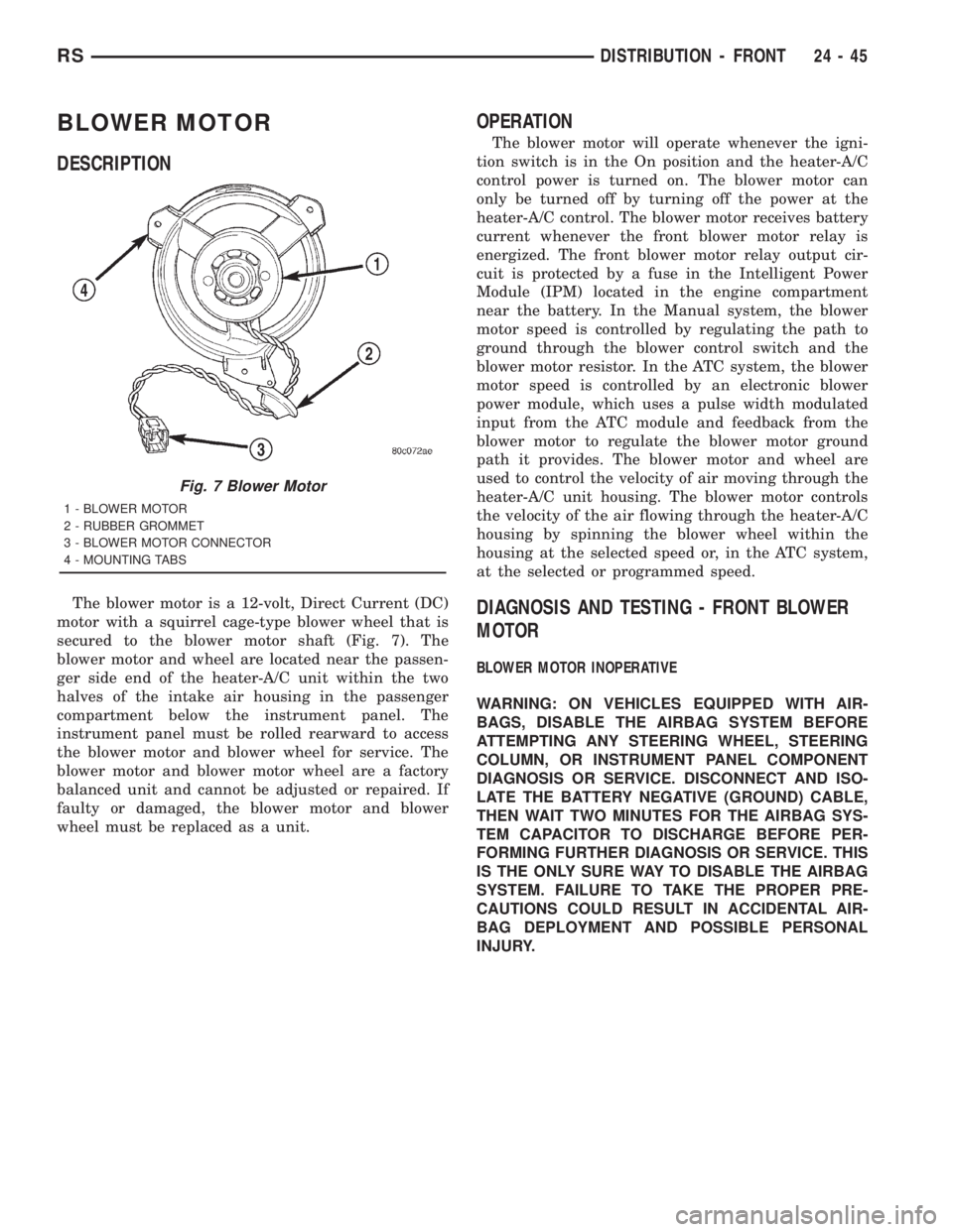
The blower motor is a 12-volt, Direct Current (DC)
motor with a squirrel cage-type blower wheel that is
secured to the blower motor shaft (Fig. 7). The
blower motor and wheel are located near the passen-
ger side end of the heater-A/C unit within the two
halves of the intake air housing in the passenger
compartment below the instrument panel. The
instrument panel must be rolled rearward to access
the blower motor and blower wheel for service. The
blower motor and blower motor wheel are a factory
balanced unit and cannot be adjusted or repaired. If
faulty or damaged, the blower motor and blower
wheel must be replaced as a unit.
OPERATION
The blower motor will operate whenever the igni-
tion switch is in the On position and the heater-A/C
control power is turned on. The blower motor can
only be turned off by turning off the power at the
heater-A/C control. The blower motor receives battery
current whenever the front blower motor relay is
energized. The front blower motor relay output cir-
cuit is protected by a fuse in the Intelligent Power
Module (IPM) located in the engine compartment
near the battery. In the Manual system, the blower
motor speed is controlled by regulating the path to
ground through the blower control switch and the
blower motor resistor. In the ATC system, the blower
motor speed is controlled by an electronic blower
power module, which uses a pulse width modulated
input from the ATC module and feedback from the
blower motor to regulate the blower motor ground
path it provides. The blower motor and wheel are
used to control the velocity of air moving through the
heater-A/C unit housing. The blower motor controls
the velocity of the air flowing through the heater-A/C
housing by spinning the blower wheel within the
housing at the selected speed or, in the ATC system,
at the selected or programmed speed.
DIAGNOSIS AND TESTING - FRONT BLOWER
MOTOR
BLOWER MOTOR INOPERATIVE
WARNING: ON VEHICLES EQUIPPED WITH AIR-
BAGS, DISABLE THE AIRBAG SYSTEM BEFORE
ATTEMPTING ANY STEERING WHEEL, STEERING
COLUMN, OR INSTRUMENT PANEL COMPONENT
DIAGNOSIS OR SERVICE. DISCONNECT AND ISO-
LATE THE BATTERY NEGATIVE (GROUND) CABLE,
THEN WAIT TWO MINUTES FOR THE AIRBAG SYS-
TEM CAPACITOR TO DISCHARGE BEFORE PER-
FORMING FURTHER DIAGNOSIS OR SERVICE. THIS
IS THE ONLY SURE WAY TO DISABLE THE AIRBAG
SYSTEM. FAILURE TO TAKE THE PROPER PRE-
CAUTIONS COULD RESULT IN ACCIDENTAL AIR-
BAG DEPLOYMENT AND POSSIBLE PERSONAL
INJURY.
Fig. 7 Blower Motor
1 - BLOWER MOTOR
2 - RUBBER GROMMET
3 - BLOWER MOTOR CONNECTOR
4 - MOUNTING TABS
RSDISTRIBUTION - FRONT24-45
Page 3686 of 4284
system control switch on the front heater-A/C control
is not in the Off position. The blower motor can only
be turned off by turning off the rear system at the
front heater-A/C control. The blower motor receives
battery current whenever the rear blower motor
relay is energized. The rear blower motor relay out-
put circuit is protected by a fuse in the Intelligent
Power Module (IPM) located in the engine compart-
ment near the battery. In the MTC system, the
blower motor speed is controlled by regulating the
path to ground through the blower control switch and
the blower motor resistor. In the ATC system, the
blower motor speed is controlled by an electronic
blower power module, which uses a pulse width mod-
ulated input from the ATC module and feedback from
the blower motor to regulate the blower motor
ground path it provides. The blower motor and wheel
are used to control the velocity of air moving through
the rear heater-A/C unit housing. The blower motor
controls the velocity of the air flowing through the
rear heater-A/C housing by spinning the blower
wheel within the housing at the selected speed or, in
the ATC system, at the selected or programmed
speed.
DIAGNOSIS AND TESTING - REAR BLOWER
MOTOR
BLOWER MOTOR INOPERATIVE
(1) Check the fuse (Fuse 12 - 25 ampere) in the
Intelligent Power Module (IPM). If OK, go to Step 2.
If not OK, repair the shorted circuit or component as
required and replace the faulty fuse.
(2) Turn the ignition switch to the On position. Be
certain that the rear heater-A/C control power is
turned on. Check for battery voltage at the fuse
(Fuse 12 - 25 ampere) in the IPM. If OK, go to Step
3. If not OK, proceed to diagnosis of the rear blower
motor relay. (Refer to 24 - HEATING & AIR CONDI-TIONING/CONTROLS - REAR/BLOWER MOTOR
RELAY - DIAGNOSIS AND TESTING).
(3) Turn the ignition switch to the Off position.
Disconnect and isolate the battery negative cable.
Disconnect the rear HVAC wire harness connector for
the rear blower motor resistor (Manual Temperature
Control) or the rear blower power module (Automatic
Temperature Control) from the resistor or module
connector receptacle. Reconnect the battery negative
cable. Turn the ignition switch to the On position. Be
certain that the rear heater-A/C control power is
turned on. Check for battery voltage at the fused
rear blower motor relay output circuit cavity of the
rear HVAC wire harness connector for the rear
blower motor resistor (MTC) or the rear blower
power module (ATC). If OK, go to Step 4. If not OK,
repair the open fused front blower motor relay output
circuit to the IPM as required.
(4) Turn the ignition switch to the Off position.
Disconnect and isolate the battery negative cable.
Disconnect the rear blower motor pigtail wire connec-
tor from the take out and connector of the rear
HVAC wire harness (MTC) or the connector recepta-
cle of the rear blower power module (ATC). Use
jumper wires to connect a battery and ground feeds
to the blower motor pigtail wire connector. The
blower motor should operate. If OK with MTC, pro-
ceed to diagnosis of the rear blower motor resistor.
(Refer to 24 - HEATING & AIR CONDITIONING/
CONTROLS - REAR/BLOWER MOTOR RESISTOR -
DIAGNOSIS AND TESTING). If OK with ATC, use a
DRBIII scan tool to diagnose the rear blower power
module. Refer to the appropriate diagnostic informa-
tion. If not OK with MTC or ATC, replace the faulty
rear blower motor.
BLOWER MOTOR NOISE OR VIBRATION
Refer to the Blower Motor Noise/Vibration Diagno-
sis chart (Fig. 4).
24 - 56 DISTRIBUTION - REARRS
BLOWER MOTOR (Continued)
Page 3752 of 4284
put component, it can verify that the command was
carried out by monitoring specific input signals for
expected changes. For example, when the PCM com-
mands the Idle Air Control (IAC) Motor to a specific
position under certain operating conditions, it expects
to see a specific (target) idle speed (RPM). If it does
not, it stores a DTC.
PCM outputs monitored for functionality include:
²Fuel Injectors
²Ignition Coils
²Torque Converter Clutch Solenoid
²Idle Air Control
²Purge Solenoid
²EGR Solenoid
²LDP Solenoid
²Radiator Fan Control
²Trans Controls
OXYGEN SENSOR (O2S) MONITOR
DESCRIPTIONÐEffective control of exhaust
emissions is achieved by an oxygen feedback system.
The most important element of the feedback system
is the O2S. The O2S is located in the exhaust path.
Once it reaches operating temperature 300É to 350ÉC
(572É to 662ÉF), the sensor generates a voltage that
is inversely proportional to the amount of oxygen in
the exhaust. When there is a large amount of oxygen
in the exhaust caused by a lean condition, the sensor
produces a low voltage, below 450 mV. When the oxy-
gen content is lower, caused by a rich condition, the
sensor produces a higher voltage, above 450mV.
The information obtained by the sensor is used to
calculate the fuel injector pulse width. The PCM is
programmed to maintain the optimum air/fuel ratio.
At this mixture ratio, the catalyst works best to
remove hydrocarbons (HC), carbon monoxide (CO)
and nitrous oxide (NOx) from the exhaust.
The O2S is also the main sensing element for the
EGR, Catalyst and Fuel Monitors.
The O2S may fail in any or all of the following
manners:
²Slow response rate (Big Slope)
²Reduced output voltage (Half Cycle)
²Heater Performance
Slow Response Rate (Big Slope)ÐResponse rate
is the time required for the sensor to switch from
lean to rich signal output once it is exposed to a
richer than optimum A/F mixture or vice versa. As
the PCM adjusts the air/fuel ratio, the sensor must
be able to rapidly detect the change. As the sensor
ages, it could take longer to detect the changes in the
oxygen content of the exhaust gas. The rate of
change that an oxygen sensor experiences is called
'Big Slope'. The PCM checks the oxygen sensor volt-
age in increments of a few milliseconds.Reduced Output Voltage (Half Cycle)ÐThe
output voltage of the O2S ranges from 0 to 1 volt. A
good sensor can easily generate any output voltage in
this range as it is exposed to different concentrations
of oxygen. To detect a shift in the A/F mixture (lean
or rich), the output voltage has to change beyond a
threshold value. A malfunctioning sensor could have
difficulty changing beyond the threshold value. Each
time the voltage signal surpasses the threshold, a
counter is incremented by one. This is called the Half
Cycle Counter.
Heater PerformanceÐThe heater is tested by a
separate monitor. Refer to the Oxygen Sensor Heater
Monitor.
OPERATIONÐAs the Oxygen Sensor signal
switches, the PCM monitors the half cycle and big
slope signals from the oxygen sensor. If during the
test neither counter reaches a predetermined value, a
malfunction is entered and a Freeze Frame is stored.
Only one counter reaching its predetermined value is
needed for the monitor to pass.
The Oxygen Sensor Monitor is a two trip monitor
that is tested only once per trip. When the Oxygen
Sensor fails the test in two consecutive trips, the
MIL is illuminated and a DTC is set. The MIL is
extinguished when the Oxygen Sensor monitor
passes in three consecutive trips. The DTC is erased
from memory after 40 consecutive warm-up cycles
without test failure.
Enabling ConditionsÐThe following conditions
must typically be met for the PCM to run the oxygen
sensor monitor:
²Battery voltage
²Engine temperature
²Engine run time
²Engine run time at a predetermined speed
²Engine run time at a predetermined speed and
throttle opening
²Transmission in gear (automatic only)
²Fuel system in Closed Loop
²Long Term Adaptive (within parameters)
²Power Steering Switch in low PSI (no load)
²Engine at idle
²Fuel level above 15%
²Ambient air temperature
²Barometric pressure
²Engine RPM within acceptable range of desired
idle
²Closed throttle speed
Pending ConditionsÐThe Task Manager typi-
cally does not run the Oxygen Sensor Monitor if over-
lapping monitors are running or the MIL is
illuminated for any of the following:
²Misfire Monitor
²Front Oxygen Sensor and Heater Monitor
²MAP Sensor
25 - 2 EMISSIONS CONTROLRS
EMISSIONS CONTROL (Continued)
Page 3756 of 4284
VACUUM ASSIST
The PCM cannot detect leaks or restrictions in the
vacuum circuits of vacuum assisted engine control
system devices. However, these could cause the PCM
to store a MAP sensor diagnostic trouble code and
cause a high idle condition.
PCM SYSTEM GROUND
The PCM cannot determine a poor system ground.
However, one or more diagnostic trouble codes may
be generated as a result of this condition. The mod-
ule should be mounted to the body at all times, also
during diagnostic.
PCM CONNECTOR ENGAGEMENT
The PCM may not be able to determine spread or
damaged connector pins. However, it might store
diagnostic trouble codes as a result of spread connec-
tor pins.
DESCRIPTION - MONITORED SYSTEMS
There are new electronic circuit monitors that
check fuel, emission, engine and ignition perfor-
mance. These monitors use information from various
sensor circuits to indicate the overall operation of the
fuel, engine, ignition and emission systems and thus
the emissions performance of the vehicle.
The fuel, engine, ignition and emission systems
monitors do not indicate a specific component prob-
lem. They do indicate that there is an implied prob-
lem within one of the systems and that a specific
problem must be diagnosed.
If any of these monitors detect a problem affecting
vehicle emissions, the Malfunction Indicator (Check
Engine) Lamp will be illuminated. These monitors
generate Diagnostic Trouble Codes that can be dis-
played with the check engine lamp or a scan tool.
The following is a list of the system monitors:
²EGR Monitor
²Misfire Monitor
²Fuel System Monitor
²Oxygen Sensor Monitor
²Oxygen Sensor Heater Monitor
²Catalyst Monitor
²Evaporative System Leak Detection Monitor
Following is a description of each system monitor,
and its DTC.
Refer to the appropriate Powertrain Diagnos-
tics Procedures manual for diagnostic proce-
dures.
OXYGEN SENSOR (O2S) MONITOR
Effective control of exhaust emissions is achieved
by an oxygen feedback system. The most important
element of the feedback system is the O2S. The O2S
is located in the exhaust path. Once it reaches oper-ating temperatures of 300É to 350ÉC (572É to 662ÉF),
the sensor generates a voltage that is inversely pro-
portional to the amount of oxygen in the exhaust.
The information obtained by the sensor is used to
calculate the fuel injector pulse width. The PCM is
programmed to maintain the optimum air/fuel ratio.
At this mixture ratio, the catalyst works best to
remove hydrocarbons (HC), carbon monoxide (CO)
and nitrous oxide (NOx) from the exhaust.
The O2S is also the main sensing element for the
EGR, Catalyst and Fuel Monitors.
The O2S may fail in any or all of the following
manners:
²Slow response rate
²Reduced output voltage
²Dynamic shift
²Shorted or open circuits
Response rate is the time required for the sensor to
switch from lean to rich once it is exposed to a richer
than optimum A/F mixture or vice versa. As the sen-
sor starts malfunctioning, it could take longer to
detect the changes in the oxygen content of the
exhaust gas.
The output voltage of the O2S ranges from 0 to 1
volt. A good sensor can easily generate any output
voltage in this range as it is exposed to different con-
centrations of oxygen. To detect a shift in the A/F
mixture (lean or rich), the output voltage has to
change beyond a threshold value. A malfunctioning
sensor could have difficulty changing beyond the
threshold value.
OXYGEN SENSOR HEATER MONITOR
If there is an oxygen sensor (O2S) DTC as well as
a O2S heater DTC, the O2S fault MUST be repaired
first. After the O2S fault is repaired, verify that the
heater circuit is operating correctly.
Effective control of exhaust emissions is achieved
by an oxygen feedback system. The most important
element of the feedback system is the O2S. The O2S
is located in the exhaust path. Once it reaches oper-
ating temperatures of 300É to 350ÉC (572 É to 662ÉF),
the sensor generates a voltage that is inversely pro-
portional to the amount of oxygen in the exhaust.
The information obtained by the sensor is used to
calculate the fuel injector pulse width. This main-
tains a 14.7 to 1 Air Fuel (A/F) ratio. At this mixture
ratio, the catalyst works best to remove hydrocarbons
(HC), carbon monoxide (CO) and nitrogen oxide
(NOx) from the exhaust.
The voltage readings taken from the O2S are very
temperature sensitive. The readings are not accurate
below 300ÉC. Heating of the O2S is done to allow the
engine controller to shift to closed loop control as
soon as possible. The heating element used to heat
25 - 6 EMISSIONS CONTROLRS
EMISSIONS CONTROL (Continued)
Page 3757 of 4284
the O2S must be tested to ensure that it is heating
the sensor properly.
The O2S circuit is monitored for a drop in voltage.
The sensor output is used to test the heater by iso-
lating the effect of the heater element on the O2S
output voltage from the other effects.
EGR MONITOR
The Powertrain Control Module (PCM) performs
an on-board diagnostic check of the EGR system.
The EGR monitor is used to test whether the EGR
system is operating within specifications. The diag-
nostic check activates only during selected engine/
driving conditions. When the conditions are met, the
EGR is turned off (solenoid energized) and the O2S
compensation control is monitored. Turning off the
EGR shifts the air fuel (A/F) ratio in the lean direc-
tion. The O2S data should indicate an increase in the
O2 concentration in the combustion chamber when
the exhaust gases are no longer recirculated. While
this test does not directly measure the operation of
the EGR system, it can be inferred from the shift in
the O2S data whether the EGR system is operating
correctly. Because the O2S is being used, the O2S
test must pass its test before the EGR test.
MISFIRE MONITOR
Excessive engine misfire results in increased cata-
lyst temperature and causes an increase in HC emis-
sions. Severe misfires could cause catalyst damage.
To prevent catalytic convertor damage, the PCM
monitors engine misfire.
The Powertrain Control Module (PCM) monitors
for misfire during most engine operating conditions
(positive torque) by looking at changes in the crank-
shaft speed. If a misfire occurs the speed of the
crankshaft will vary more than normal.
FUEL SYSTEM MONITOR
To comply with clean air regulations, vehicles are
equipped with catalytic converters. These converters
reduce the emission of hydrocarbons, oxides of nitro-
gen and carbon monoxide. The catalyst works best
when the air fuel (A/F) ratio is at or near the opti-
mum of 14.7 to 1.
The PCM is programmed to maintain the optimum
air/fuel ratio. This is done by making short term cor-
rections in the fuel injector pulse width based on the
O2S output. The programmed memory acts as a self
calibration tool that the engine controller uses to
compensate for variations in engine specifications,
sensor tolerances and engine fatigue over the life
span of the engine. By monitoring the actual air-fuel
ratio with the O2S (short term) and multiplying that
with the program long-term (adaptive) memory and
comparing that to the limit, it can be determined
whether it will pass an emissions test. If a malfunc-tion occurs such that the PCM cannot maintain the
optimum A/F ratio, then the MIL will be illuminated.
CATALYST MONITOR
To comply with clean air regulations, vehicles are
equipped with catalytic converters. These converters
reduce the emission of hydrocarbons, oxides of nitro-
gen and carbon monoxide.
Normal vehicle miles or engine misfire can cause a
catalyst to decay. A meltdown of the ceramic core can
cause a reduction of the exhaust passage. This can
increase vehicle emissions and deteriorate engine
performance, driveability and fuel economy.
The catalyst monitor uses dual oxygen sensors
(O2S's) to monitor the efficiency of the converter. The
dual O2S's strategy is based on the fact that as a cat-
alyst deteriorates, its oxygen storage capacity and its
efficiency are both reduced. By monitoring the oxy-
gen storage capacity of a catalyst, its efficiency can
be indirectly calculated. The upstream O2S is used to
detect the amount of oxygen in the exhaust gas
before the gas enters the catalytic converter. The
PCM calculates the A/F mixture from the output of
the O2S. A low voltage indicates high oxygen content
(lean mixture). A high voltage indicates a low content
of oxygen (rich mixture).
When the upstream O2S detects a lean condition,
there is an abundance of oxygen in the exhaust gas.
A functioning converter would store this oxygen so it
can use it for the oxidation of HC and CO. As the
converter absorbs the oxygen, there will be a lack of
oxygen downstream of the converter. The output of
the downstream O2S will indicate limited activity in
this condition.
As the converter loses the ability to store oxygen,
the condition can be detected from the behavior of
the downstream O2S. When the efficiency drops, no
chemical reaction takes place. This means the con-
centration of oxygen will be the same downstream as
upstream. The output voltage of the downstream
O2S copies the voltage of the upstream sensor. The
only difference is a time lag (seen by the PCM)
between the switching of the O2S's.
To monitor the system, the number of lean-to-rich
switches of upstream and downstream O2S's is
counted. The ratio of downstream switches to
upstream switches is used to determine whether the
catalyst is operating properly. An effective catalyst
will have fewer downstream switches than it has
upstream switches i.e., a ratio closer to zero. For a
totally ineffective catalyst, this ratio will be one-to-
one, indicating that no oxidation occurs in the device.
The system must be monitored so that when cata-
lyst efficiency deteriorates and exhaust emissions
increase to over the legal limit, the MIL (Check
Engine lamp) will be illuminated.
RSEMISSIONS CONTROL25-7
EMISSIONS CONTROL (Continued)
Page 3798 of 4284
3.2.3 OTHER CONTROLS
CHARGING SYSTEM
The charging system is turned on when the
engine is started and ASD relay energized. When
the ASD relay is on, ASD output voltage is supplied
to the ASD sense circuit at the PCM. This voltage is
connected in some cases, through the PCM and
supplied to one of the generator field terminals
(Gen Source +). All others, the Gen field is con-
nected directly to the ASD output voltage. The
amount of current produced by the generator is
controlled by the Electronic Voltage Regulator
(EVR) circuitry, in the PCM. Battery temperature is
determined from IAT. This temperature along with
sensed line voltage, is used by the PCM to vary the
battery charging rate. This is done by cycling the
ground path to the other generator field terminal
(Gen field driver).
SPEED CONTROL SYSTEM
The PCM controls vehicle speed by operation of
the speed control servo vacuum and vent solenoids.
Energizing the vacuum solenoid applies vacuum to
the servo to increase throttle position. Operation of
the vent solenoid slowly releases the vacuum allow-
ing throttle position to decrease. A special dump
solenoid allows immediate release of throttle posi-
tion caused by braking, cruise control switch turned
off, shifting into neutral, excessive RPM (tires spin-
ning) or ignition off.
LEAK DETECTION PUMP SYSTEM (IF EQUIPPED)
The leak detection pump is a device that pressur-
izes the evaporative system to determine if there
are any leaks. When certain conditions are met, the
PCM will activate the pump and start counting
pump strokes. If the pump stops within a calibrated
number of strokes, the system is determined to be
normal. If the pump does not stop or stops too soon,
a DTC will be set.
3.2.4 PCM OPERATING MODES
As input signals to the PCM change, the PCM
adjusts its response to output devices. For example,
the PCM must calculate a different injector pulse
width and ignition timing for idle than it does for
wide open throttle. There are several different
modes of operation that determine how the PCM
responds to the various input signals.
There are two types of engine control operation:
open loopandclosed loop.
Inopen loopoperation, the PCM receives input
signals and responds according to preset program-
ming. Inputs from the heated oxygen sensors are
not monitored.Inclosed loopoperation, the PCM monitors the
inputs from the heated oxygen sensors. This input
indicates to the PCM whether or not the calculated
injector pulse width results in the ideal air-fuel
ratio of 14.7 parts air to 1 part fuel. By monitoring
the exhaust oxygen content through the oxygen
sensor, the PCM can fine tune injector pulse width.
Fine tuning injector pulse width allows the PCM to
achieve the lowest emission levels while maintain-
ing optimum fuel economy.
The engine start-up (crank), engine warm-up,
and wide open throttle modes are open loop modes.
Under most operating conditions, closed loop modes
occur with the engine at operating temperature.
IGNITION SWITCH ON (ENGINE OFF) MODE
When the ignition switch activates the fuel injec-
tion system, the following actions occur:
1. The PCM determines atmospheric air pressure
from the MAP sensor input to determine basic
fuel strategy.
2. The PCM monitors the engine coolant tempera-
ture sensor and throttle position sensor input.
The PCM modifies fuel strategy based on this
input.
When the key is in the on position and the engine
is not running (zero rpm), the auto shutdown relay
and fuel pump relay are not energized. Therefore,
voltage is not supplied to the fuel pump, ignition
coil, and fuel injectors.
Engine Start-up ModeÐ This is an open loop
mode. The following actions occur when the starter
motor is engaged:
1. The auto shutdown and fuel pump relays are
energized. If the PCM does not receive the cam-
shaft and crankshaft signal within approxi-
mately one second, these relays are de-
energized.
2. The PCM energizes all fuel injectors until it
determines crankshaft position from the cam-
shaft and crankshaft signals. The PCM deter-
mines crankshaft position within one engine
revolution. After the camshaft position has been
determined, the PCM energizes the fuel injectors
in sequence. The PCM adjusts the injector pulse
width and synchronizes the fuel injectors by
controlling the fuel injectors' ground paths.
3. Once the engine idles within 64 rpm of its target
engine speed, the PCM compares the current
MAP sensor value with the value received dur-
ing the ignition switch on (zero rpm) mode. A
diagnostic trouble code is written to PCM mem-
ory if a minimum difference between the two
values is not found.
4
GENERAL INFORMATION
Page 3799 of 4284
Once the auto shutdown and fuel pump relays
have been energized, the PCM determines the fuel
injector pulse width based on the following:
± engine coolant temperature
± manifold absolute pressure
± intake air temperature
± engine revolutions
± throttle position
The PCM determines the spark advance based on
the following:
± engine coolant temperature
± crankshaft position
± intake air temperature
± manifold absolute pressure
± throttle position
Engine Warm-Up Modeþ This is an open loop
mode. The PCM adjusts injector pulse width and
controls injector synchronization by controlling the
fuel injectors' ground paths. The PCM adjusts igni-
tion timing and engine idle speed. The PCM adjusts
the idle speed by controlling the idle air control
motor.
Cruise or Idle Modeþ When the engine is at
normal operating temperature, this is a closed loop
mode.
Acceleration Modeþ This is a closed loop mode.
The PCM recognizes an increase in throttle position
and a decrease in Manifold Vacuum as engine load
increases. In response, the PCM increases the in-
jector pulse width to meet the increased load. The
A/C compressor may be de-energized for a short
period of time.
Decelerationþ This is a closed loop mode. The
PCM recognizes a decrease in throttle position and
an increase in Manifold Vacuum as engine load
decreases. In response, the PCM decreases the
injector pulse width to meet the decreased load.
Full injector shut off may be obtained during high
speed deceleration.
Wide Open Throttle Modeþ This is an open
loop mode. The throttle position sensor notifies the
PCM of a wide open throttle condition. Once a wide
open throttle is sensed, the PCM de-energizes the
A/C compressor clutch relay for 20 seconds.
3.2.5 NON-MONITORED CIRCUITS
The PCM does not monitor the following circuits,
systems, and conditions even though they could
have malfunctions that result in driveability prob-
lems. A diagnostic code may not be displayed for the
following conditions. However, problems with these
systems may cause a diagnostic code to be displayed
for other systems. For example, a fuel pressure
problem will not register a diagnostic code directly,
but could cause a rich or lean condition. This couldcause an oxygen sensor, fuel system, or misfire
monitor trouble code to be stored in the PCM.
Engine Timingþ The PCM cannot detect an
incorrectly indexed timing chain, camshaft
sprocket, or crankshaft sprocket. The PCM also
cannot detect an incorrectly indexed distributor.(*)
Fuel Pressureþ Fuel pressure is controlled by
the fuel pressure regulator. The PCM cannot detect
a clogged fuel pump inlet filter, clogged in-line filter,
or a pinched fuel supply.(*)
Fuel Injectorsþ The PCM cannot detect if a fuel
injector is clogged, the pintle is sticking, or the
wrong injectors are installed.(*)
Fuel Requirementsþ Poor quality gasoline can
cause problems such as hard starting, stalling, and
stumble. Use of methanol-gasoline blends may re-
sult in starting and driveability problems. See indi-
vidual symptoms and their definitions in Section
6.0 (Glossary of Terms).
PCM Groundsþ The PCM cannot detect a poor
system ground. However, a diagnostic trouble code
may be stored in the PCM as a result of this
condition.
Throttle Body Air Flowþ The PCM cannot
detect a clogged or restricted air cleaner inlet or
filter element.(*)
Exhaust Systemþ The PCM cannot detect a
plugged, restricted, or leaking exhaust system.(*)
Cylinder Compressionþ The PCM cannot de-
tect uneven, low, or high engine cylinder compres-
sion.(*)
Excessive Oil Consumptionþ Although the
PCM monitors the exhaust stream oxygen content
through the oxygen sensor when the system is in a
closed loop, it cannot determine excessive oil con-
sumption.
NOTE: ANY OF THESE CONDITIONS
COULD RESULT IN A RICH OR LEAN
CONDITION CAUSING AN OXYGEN SENSOR
TROUBLE CODE TO BE STORED IN THE
PCM, OR THE VEHICLE MAY EXHIBIT ONE
OR MORE OF THE DRIVEABILITY
SYMPTOMS LISTED IN THE TABLE OF
CONTENTS.
3.2.6 SKIS OVERVIEW
The Sentry Key Immobilizer System (SKIS) is
designed to prevent unauthorized vehicle opera-
tion. The system consists of a Sentry Key Immobi-
lizer Module (SKIM), ignition key(s) equipped with
a transponder chip and PCM. When the ignition
switch is turned on, the SKIM interrogates the
ignition key. If the ignition key is Valid or Invalid,
the SKIM sends a PCI Bus message to the PCM
indicating ignition key status. Upon receiving this
5
GENERAL INFORMATION