2001 CHRYSLER VOYAGER check engine
[x] Cancel search: check enginePage 4052 of 4284
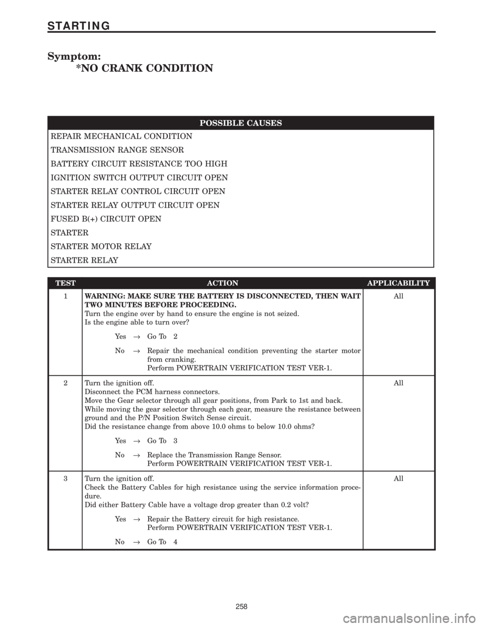
Symptom:
*NO CRANK CONDITION
POSSIBLE CAUSES
REPAIR MECHANICAL CONDITION
TRANSMISSION RANGE SENSOR
BATTERY CIRCUIT RESISTANCE TOO HIGH
IGNITION SWITCH OUTPUT CIRCUIT OPEN
STARTER RELAY CONTROL CIRCUIT OPEN
STARTER RELAY OUTPUT CIRCUIT OPEN
FUSED B(+) CIRCUIT OPEN
STARTER
STARTER MOTOR RELAY
STARTER RELAY
TEST ACTION APPLICABILITY
1WARNING: MAKE SURE THE BATTERY IS DISCONNECTED, THEN WAIT
TWO MINUTES BEFORE PROCEEDING.
Turn the engine over by hand to ensure the engine is not seized.
Is the engine able to turn over?All
Ye s®Go To 2
No®Repair the mechanical condition preventing the starter motor
from cranking.
Perform POWERTRAIN VERIFICATION TEST VER-1.
2 Turn the ignition off.
Disconnect the PCM harness connectors.
Move the Gear selector through all gear positions, from Park to 1st and back.
While moving the gear selector through each gear, measure the resistance between
ground and the P/N Position Switch Sense circuit.
Did the resistance change from above 10.0 ohms to below 10.0 ohms?All
Ye s®Go To 3
No®Replace the Transmission Range Sensor.
Perform POWERTRAIN VERIFICATION TEST VER-1.
3 Turn the ignition off.
Check the Battery Cables for high resistance using the service information proce-
dure.
Did either Battery Cable have a voltage drop greater than 0.2 volt?All
Ye s®Repair the Battery circuit for high resistance.
Perform POWERTRAIN VERIFICATION TEST VER-1.
No®Go To 4
258
STARTING
Page 4058 of 4284
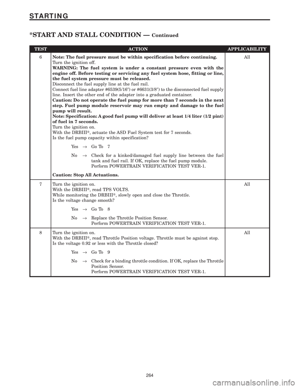
TEST ACTION APPLICABILITY
6Note: The fuel pressure must be within specification before continuing.
Turn the ignition off.
WARNING: The fuel system is under a constant pressure even with the
engine off. Before testing or servicing any fuel system hose, fitting or line,
the fuel system pressure must be released.
Disconnect the fuel supply line at the fuel rail.
Connect fuel line adapter #6539(5/169) or #6631(3/89) to the disconnected fuel supply
line. Insert the other end of the adapter into a graduated container.
Caution: Do not operate the fuel pump for more than 7 seconds in the next
step. Fuel pump module reservoir may run empty and damage to the fuel
pump will result.
Note: Specification: A good fuel pump will deliver at least 1/4 liter (1/2 pint)
of fuel in 7 seconds.
Turn the ignition on.
With the DRBIIIt, actuate the ASD Fuel System test for 7 seconds.
Is the fuel pump capacity within specification?All
Ye s®Go To 7
No®Check for a kinked/damaged fuel supply line between the fuel
tank and fuel rail. If OK, replace the fuel pump module.
Perform POWERTRAIN VERIFICATION TEST VER-1.
Caution: Stop All Actuations.
7 Turn the ignition on.
With the DRBIIIt, read TPS VOLTS.
While monitoring the DRBIIIt, slowly open and close the Throttle.
Is the voltage change smooth?All
Ye s®Go To 8
No®Replace the Throttle Position Sensor.
Perform POWERTRAIN VERIFICATION TEST VER-1.
8 Turn the ignition on.
With the DRBIIIt, read Throttle Position voltage. Throttle must be against stop.
Is the voltage 0.92 or less with the Throttle closed?All
Ye s®Go To 9
No®Check for a binding throttle condition. If OK, replace the Throttle
Position Sensor.
Perform POWERTRAIN VERIFICATION TEST VER-1.
264
STARTING
*START AND STALL CONDITION ÐContinued
Page 4059 of 4284
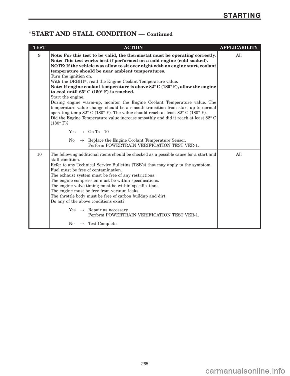
TEST ACTION APPLICABILITY
9Note: For this test to be valid, the thermostat must be operating correctly.
Note: This test works best if performed on a cold engine (cold soaked).
NOTE: If the vehicle was allow to sit over night with no engine start, coolant
temperature should be near ambient temperatures.
Turn the ignition on.
With the DRBIIIt, read the Engine Coolant Temperature value.
Note: If engine coolant temperature is above 82É C (180É F), allow the engine
to cool until 65É C (150É F) is reached.
Start the engine.
During engine warm-up, monitor the Engine Coolant Temperature value. The
temperature value change should be a smooth transition from start up to normal
operating temp 82É C (180É F). The value should reach at least 82É C (180É F).
Did the Engine Temperature value increase smoothly and did it reach at least 82É C
(180É F)?All
Ye s®Go To 10
No®Replace the Engine Coolant Temperature Sensor.
Perform POWERTRAIN VERIFICATION TEST VER-1.
10 The following additional items should be checked as a possible cause for a start and
stall condition.
Refer to any Technical Service Bulletins (TSB's) that may apply to the symptom.
Fuel must be free of contamination.
The exhaust system must be free of any restrictions.
The engine compression must be within specifications.
The engine valve timing must be within specifications.
The engine must be free from vacuum leaks.
The throttle body must be free of carbon buildup and dirt.
Do any of the above conditions exist?All
Ye s®Repair as necessary.
Perform POWERTRAIN VERIFICATION TEST VER-1.
No®Test Complete.
265
STARTING
*START AND STALL CONDITION ÐContinued
Page 4069 of 4284
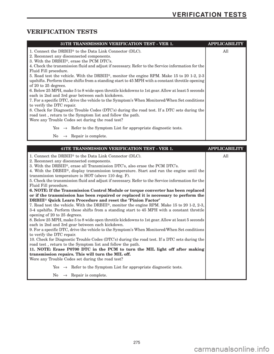
VERIFICATION TESTS
31TH TRANSMISSION VERIFICATION TEST - VER 1. APPLICABILITY
1. Connect the DRBIIItto the Data Link Connector (DLC).
2. Reconnect any disconnected components.
3. With the DRBIIIt, erase the PCM DTC's.
4. Check the transmission fluid and adjust if necessary. Refer to the Service information for the
Fluid Fill procedure.
5. Road test the vehicle. With the DRBIIIt, monitor the engine RPM. Make 15 to 20 1-2, 2-3
upshifts. Perform these shifts from a standing start to 45 MPH with a constant throttle opening
of 20 to 25 degrees.
6. Below 25 MPH, make 5 to 8 wide open throttle kickdowns to 1st gear. Allow at least 5 seconds
each in 2nd and 3rd gear between each kickdown.
7. For a specific DTC, drive the vehicle to the Symptom's When Monitored/When Set conditions
to verify the DTC repair.
8. Check for Diagnostic Trouble Codes (DTC's) during the road test. If a DTC sets during the
road test , return to the Symptom list and follow the path.
Were any Trouble Codes set during the road test?All
Ye s®Refer to the Symptom List for appropriate diagnostic tests.
No®Repair is complete.
41TE TRANSMISSION VERIFICATION TEST - VER 1. APPLICABILITY
1. Connect the DRBIIItto the Data Link Connector (DLC).
2. Reconnect any disconnected components.
3. With the DRBIIIt, erase all Transmission DTC's, also erase the PCM DTC's.
4. With the DRBIIIt, display transmission temperature. Start and run the engine until the
transmission temperature is HOT (above 110 deg. F).
5. Check the transmission fluid and adjust if necessary. Refer to the Service information for the
Fluid Fill procedure.
6. NOTE: If the Transmission Control Module or torque converter has been replaced
or if the transmission has been repaired or replaced it is necessary to perform the
DRBIIItQuick Learn Procedure and reset the(Pinion Factor(
7. Road test the vehicle. With the DRBIIIt, monitor the engine RPM. Make 15 to 20 1-2, 2-3,
3-4 upshifts. Perform these shifts from a standing start to 45 MPH with a constant throttle
opening of 20 to 25 degrees.
8. Below 25 MPH, make 5 to 8 wide open throttle kickdowns to 1st gear. Allow at least 5 seconds
each in 2nd and 3rd gear between each kickdown.
9. For a specific DTC, drive the vehicle to the Symptom's When Monitored/When Set conditions
to verify the DTC repair.
10. Check for Diagnostic Trouble Codes (DTC's) during the road test. If a DTC sets during the
road test , return to the Symptom list and follow the path.
11. NOTE: Erase P0700 DTC in the PCM to turn the MIL light off after making
transmission repairs. This will turn the MIL off.
Were any Trouble Codes set during the road test?All
Ye s®Refer to the Symptom List for appropriate diagnostic tests.
No®Repair is complete.
275
VERIFICATION TESTS
Page 4072 of 4284
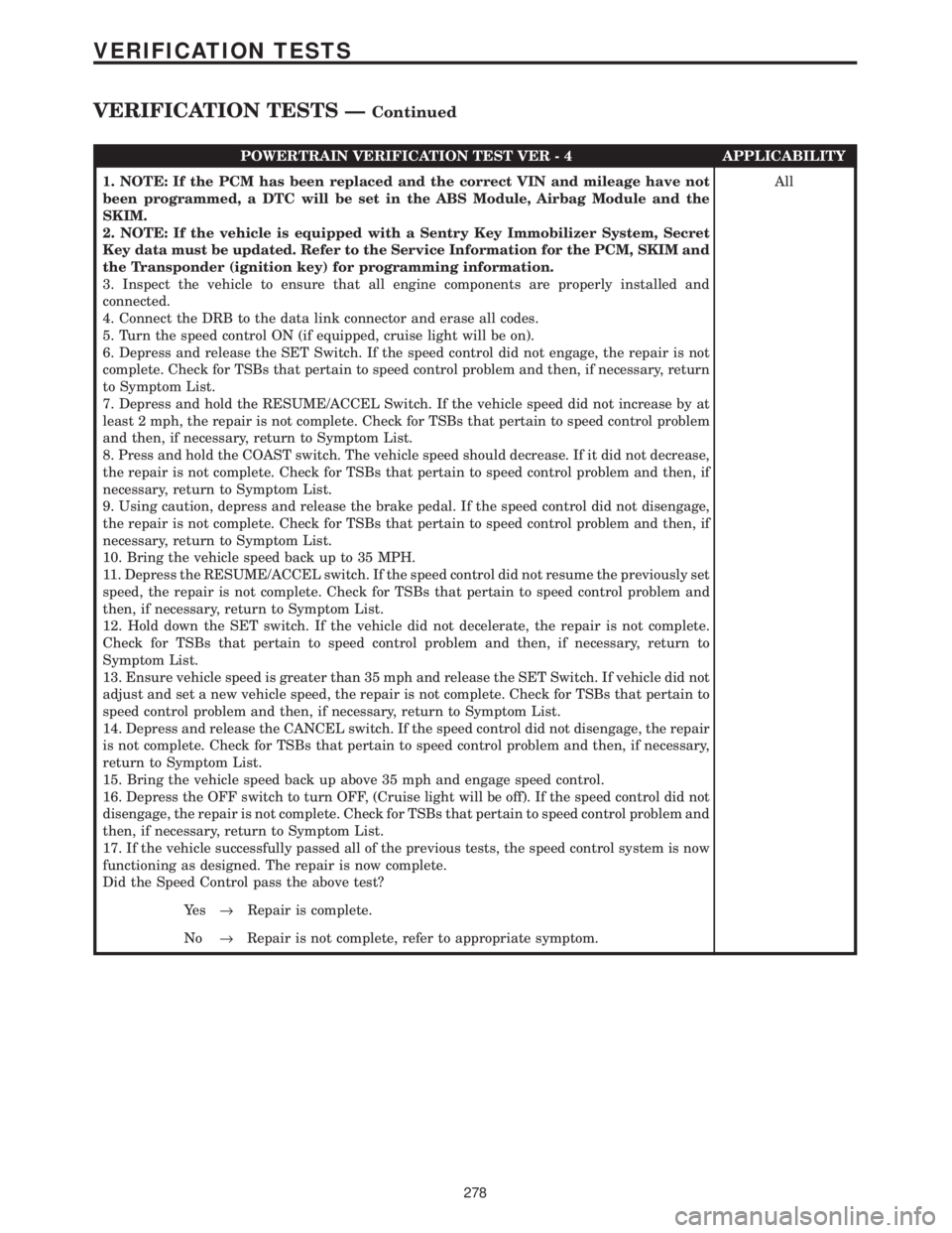
POWERTRAIN VERIFICATION TEST VER - 4 APPLICABILITY
1. NOTE: If the PCM has been replaced and the correct VIN and mileage have not
been programmed, a DTC will be set in the ABS Module, Airbag Module and the
SKIM.
2. NOTE: If the vehicle is equipped with a Sentry Key Immobilizer System, Secret
Key data must be updated. Refer to the Service Information for the PCM, SKIM and
the Transponder (ignition key) for programming information.
3. Inspect the vehicle to ensure that all engine components are properly installed and
connected.
4. Connect the DRB to the data link connector and erase all codes.
5. Turn the speed control ON (if equipped, cruise light will be on).
6. Depress and release the SET Switch. If the speed control did not engage, the repair is not
complete. Check for TSBs that pertain to speed control problem and then, if necessary, return
to Symptom List.
7. Depress and hold the RESUME/ACCEL Switch. If the vehicle speed did not increase by at
least 2 mph, the repair is not complete. Check for TSBs that pertain to speed control problem
and then, if necessary, return to Symptom List.
8. Press and hold the COAST switch. The vehicle speed should decrease. If it did not decrease,
the repair is not complete. Check for TSBs that pertain to speed control problem and then, if
necessary, return to Symptom List.
9. Using caution, depress and release the brake pedal. If the speed control did not disengage,
the repair is not complete. Check for TSBs that pertain to speed control problem and then, if
necessary, return to Symptom List.
10. Bring the vehicle speed back up to 35 MPH.
11. Depress the RESUME/ACCEL switch. If the speed control did not resume the previously set
speed, the repair is not complete. Check for TSBs that pertain to speed control problem and
then, if necessary, return to Symptom List.
12. Hold down the SET switch. If the vehicle did not decelerate, the repair is not complete.
Check for TSBs that pertain to speed control problem and then, if necessary, return to
Symptom List.
13. Ensure vehicle speed is greater than 35 mph and release the SET Switch. If vehicle did not
adjust and set a new vehicle speed, the repair is not complete. Check for TSBs that pertain to
speed control problem and then, if necessary, return to Symptom List.
14. Depress and release the CANCEL switch. If the speed control did not disengage, the repair
is not complete. Check for TSBs that pertain to speed control problem and then, if necessary,
return to Symptom List.
15. Bring the vehicle speed back up above 35 mph and engage speed control.
16. Depress the OFF switch to turn OFF, (Cruise light will be off). If the speed control did not
disengage, the repair is not complete. Check for TSBs that pertain to speed control problem and
then, if necessary, return to Symptom List.
17. If the vehicle successfully passed all of the previous tests, the speed control system is now
functioning as designed. The repair is now complete.
Did the Speed Control pass the above test?All
Ye s®Repair is complete.
No®Repair is not complete, refer to appropriate symptom.
278
VERIFICATION TESTS
VERIFICATION TESTS ÐContinued
Page 4073 of 4284
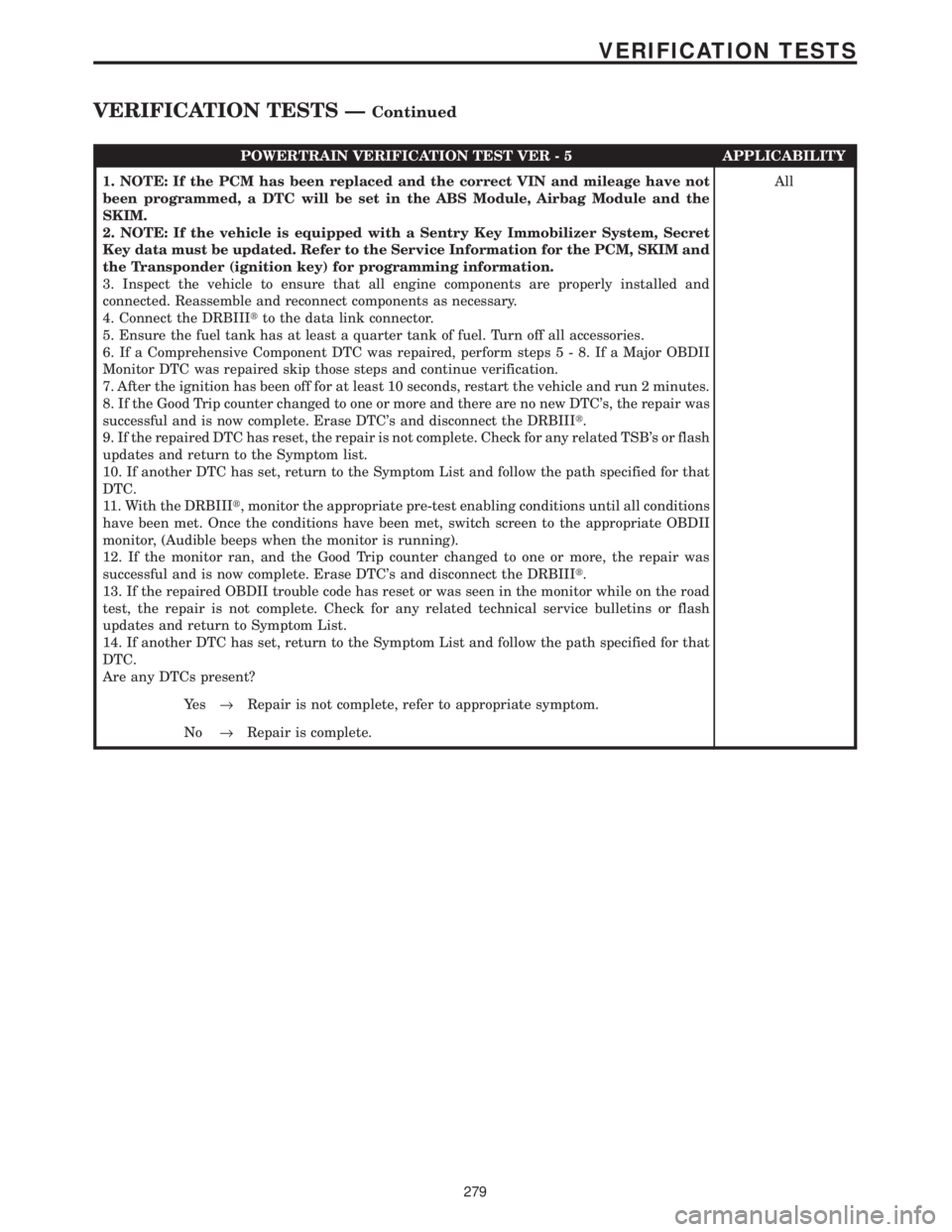
POWERTRAIN VERIFICATION TEST VER - 5 APPLICABILITY
1. NOTE: If the PCM has been replaced and the correct VIN and mileage have not
been programmed, a DTC will be set in the ABS Module, Airbag Module and the
SKIM.
2. NOTE: If the vehicle is equipped with a Sentry Key Immobilizer System, Secret
Key data must be updated. Refer to the Service Information for the PCM, SKIM and
the Transponder (ignition key) for programming information.
3. Inspect the vehicle to ensure that all engine components are properly installed and
connected. Reassemble and reconnect components as necessary.
4. Connect the DRBIIItto the data link connector.
5. Ensure the fuel tank has at least a quarter tank of fuel. Turn off all accessories.
6. If a Comprehensive Component DTC was repaired, perform steps5-8.IfaMajor OBDII
Monitor DTC was repaired skip those steps and continue verification.
7. After the ignition has been off for at least 10 seconds, restart the vehicle and run 2 minutes.
8. If the Good Trip counter changed to one or more and there are no new DTC's, the repair was
successful and is now complete. Erase DTC's and disconnect the DRBIIIt.
9. If the repaired DTC has reset, the repair is not complete. Check for any related TSB's or flash
updates and return to the Symptom list.
10. If another DTC has set, return to the Symptom List and follow the path specified for that
DTC.
11. With the DRBIIIt, monitor the appropriate pre-test enabling conditions until all conditions
have been met. Once the conditions have been met, switch screen to the appropriate OBDII
monitor, (Audible beeps when the monitor is running).
12. If the monitor ran, and the Good Trip counter changed to one or more, the repair was
successful and is now complete. Erase DTC's and disconnect the DRBIIIt.
13. If the repaired OBDII trouble code has reset or was seen in the monitor while on the road
test, the repair is not complete. Check for any related technical service bulletins or flash
updates and return to Symptom List.
14. If another DTC has set, return to the Symptom List and follow the path specified for that
DTC.
Are any DTCs present?All
Ye s®Repair is not complete, refer to appropriate symptom.
No®Repair is complete.
279
VERIFICATION TESTS
VERIFICATION TESTS ÐContinued
Page 4074 of 4284
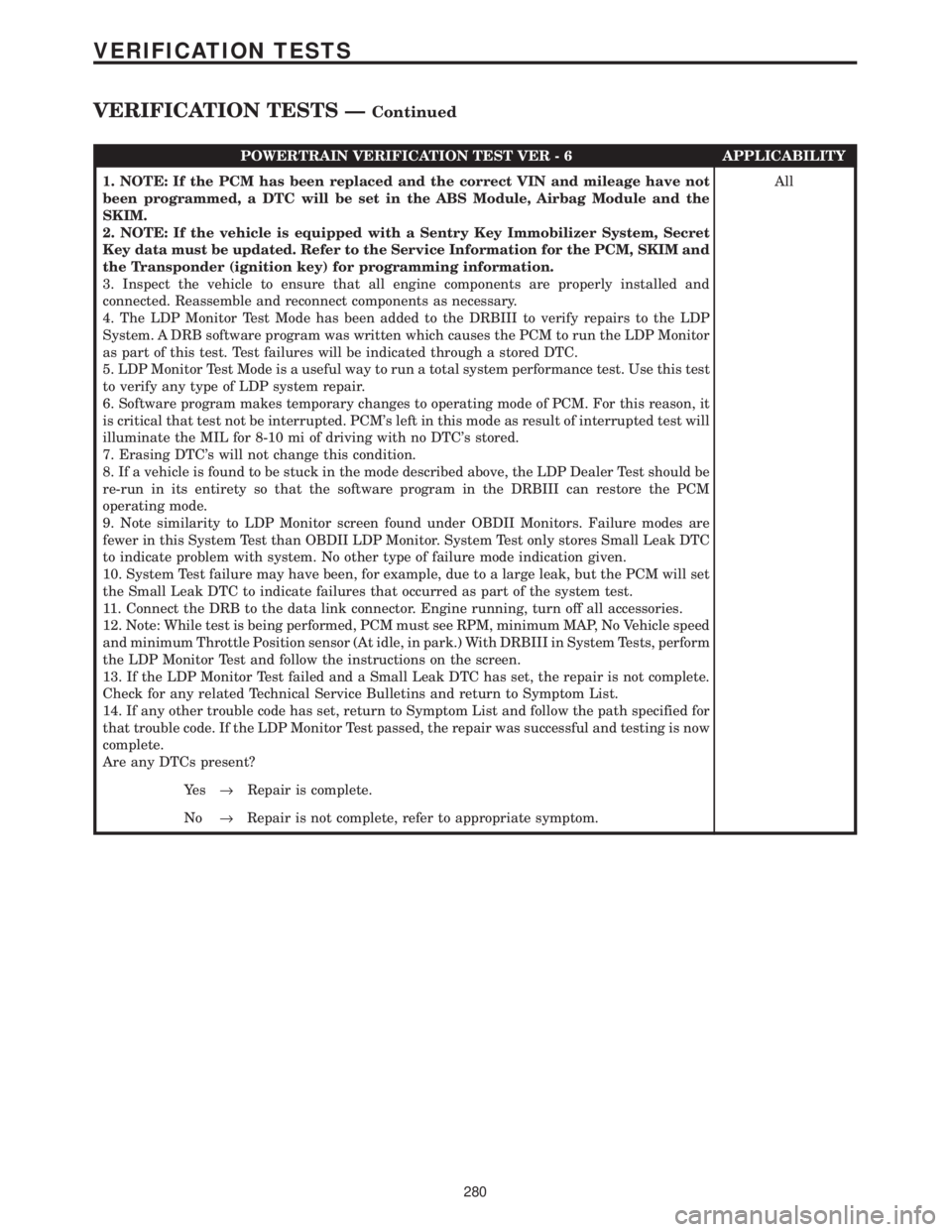
POWERTRAIN VERIFICATION TEST VER - 6 APPLICABILITY
1. NOTE: If the PCM has been replaced and the correct VIN and mileage have not
been programmed, a DTC will be set in the ABS Module, Airbag Module and the
SKIM.
2. NOTE: If the vehicle is equipped with a Sentry Key Immobilizer System, Secret
Key data must be updated. Refer to the Service Information for the PCM, SKIM and
the Transponder (ignition key) for programming information.
3. Inspect the vehicle to ensure that all engine components are properly installed and
connected. Reassemble and reconnect components as necessary.
4. The LDP Monitor Test Mode has been added to the DRBIII to verify repairs to the LDP
System. A DRB software program was written which causes the PCM to run the LDP Monitor
as part of this test. Test failures will be indicated through a stored DTC.
5. LDP Monitor Test Mode is a useful way to run a total system performance test. Use this test
to verify any type of LDP system repair.
6. Software program makes temporary changes to operating mode of PCM. For this reason, it
is critical that test not be interrupted. PCM's left in this mode as result of interrupted test will
illuminate the MIL for 8-10 mi of driving with no DTC's stored.
7. Erasing DTC's will not change this condition.
8. If a vehicle is found to be stuck in the mode described above, the LDP Dealer Test should be
re-run in its entirety so that the software program in the DRBIII can restore the PCM
operating mode.
9. Note similarity to LDP Monitor screen found under OBDII Monitors. Failure modes are
fewer in this System Test than OBDII LDP Monitor. System Test only stores Small Leak DTC
to indicate problem with system. No other type of failure mode indication given.
10. System Test failure may have been, for example, due to a large leak, but the PCM will set
the Small Leak DTC to indicate failures that occurred as part of the system test.
11. Connect the DRB to the data link connector. Engine running, turn off all accessories.
12. Note: While test is being performed, PCM must see RPM, minimum MAP, No Vehicle speed
and minimum Throttle Position sensor (At idle, in park.) With DRBIII in System Tests, perform
the LDP Monitor Test and follow the instructions on the screen.
13. If the LDP Monitor Test failed and a Small Leak DTC has set, the repair is not complete.
Check for any related Technical Service Bulletins and return to Symptom List.
14. If any other trouble code has set, return to Symptom List and follow the path specified for
that trouble code. If the LDP Monitor Test passed, the repair was successful and testing is now
complete.
Are any DTCs present?All
Ye s®Repair is complete.
No®Repair is not complete, refer to appropriate symptom.
280
VERIFICATION TESTS
VERIFICATION TESTS ÐContinued
Page 4102 of 4284

TABLE OF CONTENTS - Continued
TRANSMISSION
P0120-THROTTLE POSITION SENSOR SIGNAL CIRCUIT.....................24
P0600-SERIAL COMMUNICATION LINK MALFUNCTION.......................26
P0604-INTERNAL TCM..................................................28
P0605-INTERNAL TCM..................................................29
P0700-INTERNAL TCM..................................................30
P0705-CHECK SHIFTER SIGNAL..........................................31
P0715-INPUT SPEED SENSOR ERROR....................................38
P0720-OUTPUT SPEED SENSOR ERROR..................................42
P0725-ENGINE SPEED SENSOR CIRCUIT (3.3L/3.8L)........................46
P0725-ENGINE SPEED SENSOR CIRCUIT (3.5L)............................48
P0731-GEAR RATIO ERROR IN 1ST.......................................51
P0732-GEAR RATIO ERROR IN 2ND.......................................53
P0733-GEAR RATIO ERROR IN 3RD.......................................55
P0734-GEAR RATIO ERROR IN 4TH.......................................57
P0736-GEAR RATIO ERROR IN REVERSE..................................59
P0740-TORQUE CONVERTER CLUTCH CONTROL CIRCUIT...................61
P0750-LR SOLENOID CIRCUIT............................................63
P0755-2-4 SOLENOID CIRCUIT...........................................66
P0760-OD SOLENOID CIRCUIT...........................................69
P0765-UD SOLENOID CIRCUIT...........................................72
P1714-LOW BATTERY VOLTAGE..........................................75
P1716-BUS COMMUNICATION WITH PCM..................................79
P1717-NO COMMUNICATION WITH THE MIC...............................81
P1738-HIGH TEMPERATURE OPERATION ACTIVATED.......................83
P1739-POWER UP AT SPEED............................................85
P1765-SWITCHED BATTERY.............................................86
P1767-TRANSMISSION RELAY ALWAYS ON................................89
P1768-RELAY OUTPUT ALWAYS OFF......................................92
P1775-SOLENOID SWITCH VALVE LATCHED IN TCC POSITION...............96
P1776-SOLENOID SWITCH VALVE LATCHED IN LR POSITION................100
P1781-OD PRESSURE SWITCH SENSE CIRCUIT...........................104
P1782 - 2-4 PRESSURE SWITCH SENSE CIRCUIT..........................107
P1784-LR PRESSURE SWITCH SENSE CIRCUIT...........................110
P1787-OD HYDRAULIC PRESSURE TEST FAILURE.........................114
P1788-2/4 HYDRAULIC PRESSURE TEST FAILURE.........................118
P1789-2-4/OD HYDRAULIC PRESSURE TEST FAILURE......................122
P1790-FAULT IMMEDIATELY AFTER SHIFT................................123
P1791-LOSS OF PRIME.................................................124
P1792-BATTERY WAS DISCONNECTED...................................127
P1793-TRD LINK COMMUNICATION ERROR...............................130
P1794-SPEED SENSOR GROUND ERROR................................133
P1795-INTERNAL TCM.................................................135
P1796-AUTOSTICK SENSOR CIRCUIT....................................136
P1797-MANUAL SHIFT OVERHEAT.......................................139
P1798-WORN OUT/BURNT TRANSAXLE FLUID.............................140
P1799-CALCULATED OIL TEMP IN USE...................................142
*BRAKE SHIFT INTERLOCK OUTPUT OPEN...............................146
*CHECKING PARK/NEUTRAL SWITCH OPERATION.........................148
*INCORRECT TRANSMISSION FLUID LEVEL...............................150
*NO BACK UP LAMP OPERATION........................................151
*NO SPEEDOMETER OPERATION........................................153
*TRANSMISSION NOISY WITH NO DTC'S PRESENT........................154
ii