2001 CHRYSLER VOYAGER air condition
[x] Cancel search: air conditionPage 1421 of 4284
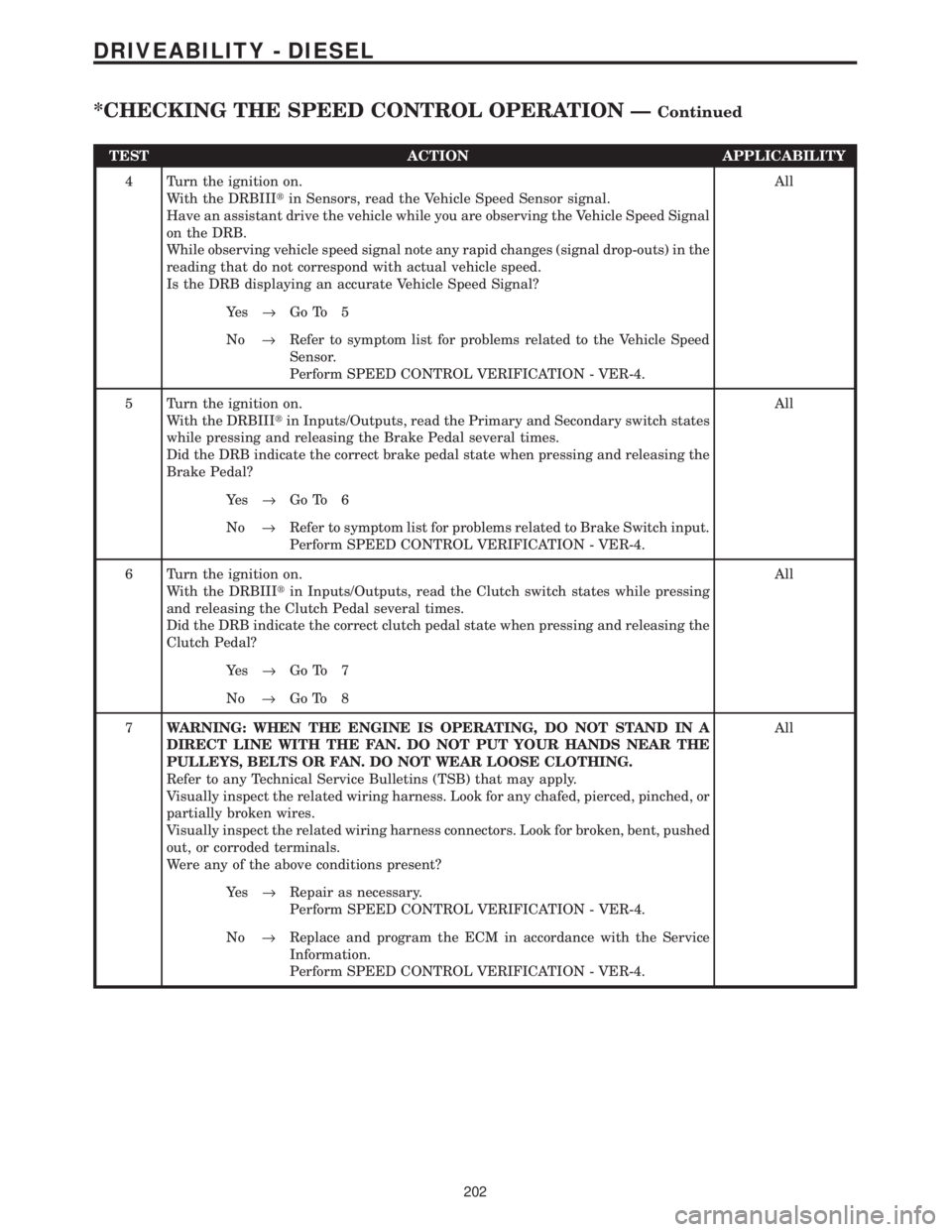
TEST ACTION APPLICABILITY
4 Turn the ignition on.
With the DRBIIItin Sensors, read the Vehicle Speed Sensor signal.
Have an assistant drive the vehicle while you are observing the Vehicle Speed Signal
on the DRB.
While observing vehicle speed signal note any rapid changes (signal drop-outs) in the
reading that do not correspond with actual vehicle speed.
Is the DRB displaying an accurate Vehicle Speed Signal?All
Ye s®Go To 5
No®Refer to symptom list for problems related to the Vehicle Speed
Sensor.
Perform SPEED CONTROL VERIFICATION - VER-4.
5 Turn the ignition on.
With the DRBIIItin Inputs/Outputs, read the Primary and Secondary switch states
while pressing and releasing the Brake Pedal several times.
Did the DRB indicate the correct brake pedal state when pressing and releasing the
Brake Pedal?All
Ye s®Go To 6
No®Refer to symptom list for problems related to Brake Switch input.
Perform SPEED CONTROL VERIFICATION - VER-4.
6 Turn the ignition on.
With the DRBIIItin Inputs/Outputs, read the Clutch switch states while pressing
and releasing the Clutch Pedal several times.
Did the DRB indicate the correct clutch pedal state when pressing and releasing the
Clutch Pedal?All
Ye s®Go To 7
No®Go To 8
7WARNING: WHEN THE ENGINE IS OPERATING, DO NOT STAND IN A
DIRECT LINE WITH THE FAN. DO NOT PUT YOUR HANDS NEAR THE
PULLEYS, BELTS OR FAN. DO NOT WEAR LOOSE CLOTHING.
Refer to any Technical Service Bulletins (TSB) that may apply.
Visually inspect the related wiring harness. Look for any chafed, pierced, pinched, or
partially broken wires.
Visually inspect the related wiring harness connectors. Look for broken, bent, pushed
out, or corroded terminals.
Were any of the above conditions present?All
Ye s®Repair as necessary.
Perform SPEED CONTROL VERIFICATION - VER-4.
No®Replace and program the ECM in accordance with the Service
Information.
Perform SPEED CONTROL VERIFICATION - VER-4.
202
DRIVEABILITY - DIESEL
*CHECKING THE SPEED CONTROL OPERATION ÐContinued
Page 1422 of 4284
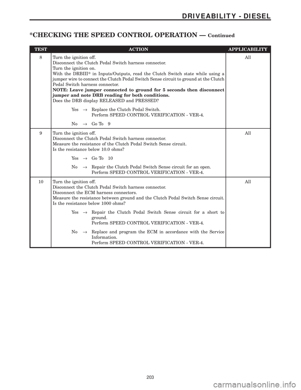
TEST ACTION APPLICABILITY
8 Turn the ignition off.
Disconnect the Clutch Pedal Switch harness connector.
Turn the ignition on.
With the DRBIIItin Inputs/Outputs, read the Clutch Switch state while using a
jumper wire to connect the Clutch Pedal Switch Sense circuit to ground at the Clutch
Pedal Switch harness connector.
NOTE: Leave jumper connected to ground for 5 seconds then disconnect
jumper and note DRB reading for both conditions.
Does the DRB display RELEASED and PRESSED?All
Ye s®Replace the Clutch Pedal Switch.
Perform SPEED CONTROL VERIFICATION - VER-4.
No®Go To 9
9 Turn the ignition off.
Disconnect the Clutch Pedal Switch harness connector.
Measure the resistance of the Clutch Pedal Switch Sense circuit.
Is the resistance below 10.0 ohms?All
Ye s®Go To 10
No®Repair the Clutch Pedal Switch Sense circuit for an open.
Perform SPEED CONTROL VERIFICATION - VER-4.
10 Turn the ignition off.
Disconnect the Clutch Pedal Switch harness connector.
Disconnect the ECM harness connectors.
Measure the resistance between ground and the Clutch Pedal Switch Sense circuit.
Is the resistance below 1000 ohms?All
Ye s®Repair the Clutch Pedal Switch Sense circuit for a short to
ground.
Perform SPEED CONTROL VERIFICATION - VER-4.
No®Replace and program the ECM in accordance with the Service
Information.
Perform SPEED CONTROL VERIFICATION - VER-4.
203
DRIVEABILITY - DIESEL
*CHECKING THE SPEED CONTROL OPERATION ÐContinued
Page 1429 of 4284
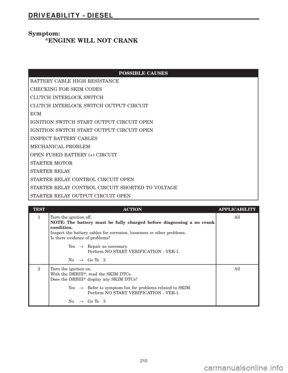
Symptom:
*ENGINE WILL NOT CRANK
POSSIBLE CAUSES
BATTERY CABLE HIGH RESISTANCE
CHECKING FOR SKIM CODES
CLUTCH INTERLOCK SWITCH
CLUTCH INTERLOCK SWITCH OUTPUT CIRCUIT
ECM
IGNITION SWITCH START OUTPUT CIRCUIT OPEN
IGNITION SWITCH START OUTPUT CIRCUIT OPEN
INSPECT BATTERY CABLES
MECHANICAL PROBLEM
OPEN FUSED BATTERY (+) CIRCUIT
STARTER MOTOR
STARTER RELAY
STARTER RELAY CONTROL CIRCUIT OPEN
STARTER RELAY CONTROL CIRCUIT SHORTED TO VOLTAGE
STARTER RELAY OUTPUT CIRCUIT OPEN
TEST ACTION APPLICABILITY
1 Turn the ignition off.
NOTE: The battery must be fully charged before diagnosing a no crank
condition.
Inspect the battery cables for corrosion, looseness or other problems.
Is there evidence of problems?All
Ye s®Repair as necessary.
Perform NO START VERIFICATION - VER-1.
No®Go To 2
2 Turn the ignition on.
With the DRBIIIt, read the SKIM DTCs.
Does the DRBIIItdisplay any SKIM DTCs?All
Ye s®Refer to symptom list for problems related to SKIM.
Perform NO START VERIFICATION - VER-1.
No®Go To 3
210
DRIVEABILITY - DIESEL
Page 1442 of 4284
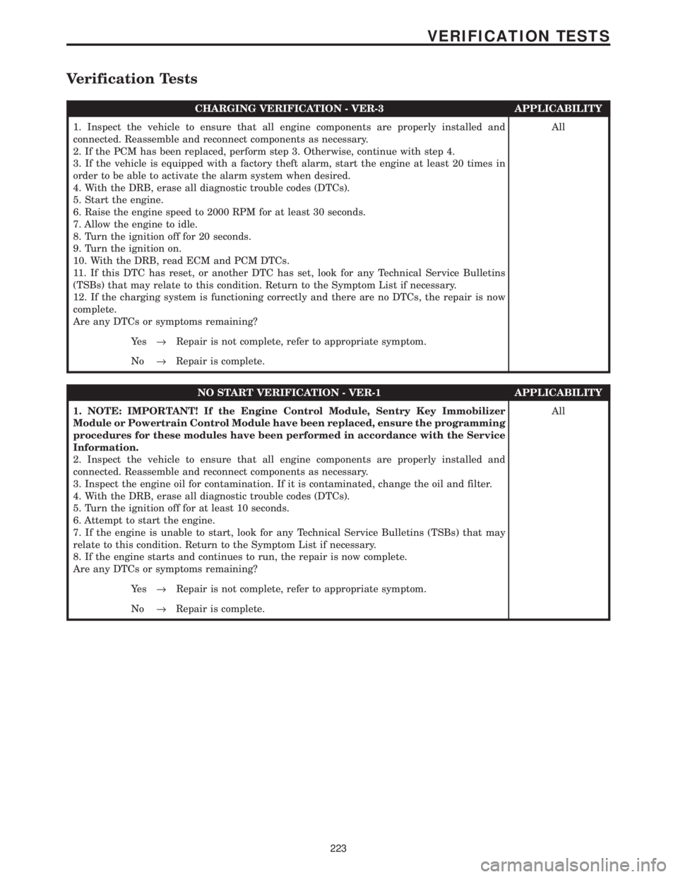
Verification Tests
CHARGING VERIFICATION - VER-3 APPLICABILITY
1. Inspect the vehicle to ensure that all engine components are properly installed and
connected. Reassemble and reconnect components as necessary.
2. If the PCM has been replaced, perform step 3. Otherwise, continue with step 4.
3. If the vehicle is equipped with a factory theft alarm, start the engine at least 20 times in
order to be able to activate the alarm system when desired.
4. With the DRB, erase all diagnostic trouble codes (DTCs).
5. Start the engine.
6. Raise the engine speed to 2000 RPM for at least 30 seconds.
7. Allow the engine to idle.
8. Turn the ignition off for 20 seconds.
9. Turn the ignition on.
10. With the DRB, read ECM and PCM DTCs.
11. If this DTC has reset, or another DTC has set, look for any Technical Service Bulletins
(TSBs) that may relate to this condition. Return to the Symptom List if necessary.
12. If the charging system is functioning correctly and there are no DTCs, the repair is now
complete.
Are any DTCs or symptoms remaining?All
Ye s®Repair is not complete, refer to appropriate symptom.
No®Repair is complete.
NO START VERIFICATION - VER-1 APPLICABILITY
1. NOTE: IMPORTANT! If the Engine Control Module, Sentry Key Immobilizer
Module or Powertrain Control Module have been replaced, ensure the programming
procedures for these modules have been performed in accordance with the Service
Information.
2. Inspect the vehicle to ensure that all engine components are properly installed and
connected. Reassemble and reconnect components as necessary.
3. Inspect the engine oil for contamination. If it is contaminated, change the oil and filter.
4. With the DRB, erase all diagnostic trouble codes (DTCs).
5. Turn the ignition off for at least 10 seconds.
6. Attempt to start the engine.
7. If the engine is unable to start, look for any Technical Service Bulletins (TSBs) that may
relate to this condition. Return to the Symptom List if necessary.
8. If the engine starts and continues to run, the repair is now complete.
Are any DTCs or symptoms remaining?All
Ye s®Repair is not complete, refer to appropriate symptom.
No®Repair is complete.
223
VERIFICATION TESTS
Page 1468 of 4284
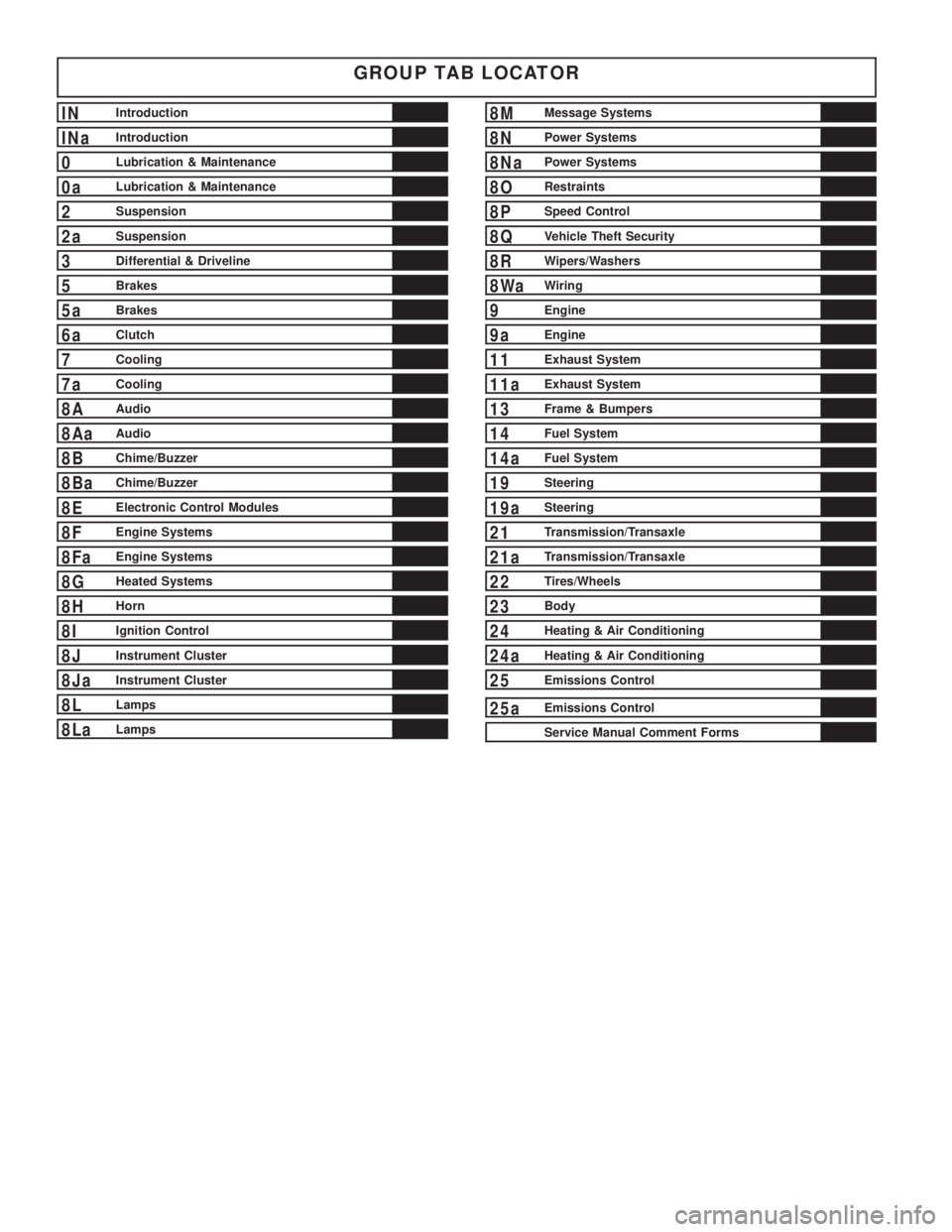
GROUP TAB LOCATOR
INIntroduction
INaIntroduction
0Lubrication & Maintenance
0aLubrication & Maintenance
2Suspension
2aSuspension
3Differential & Driveline
5Brakes
5aBrakes
6aClutch
7Cooling
7aCooling
8AAudio
8AaAudio
8BChime/Buzzer
8BaChime/Buzzer
8EElectronic Control Modules
8FEngine Systems
8FaEngine Systems
8GHeated Systems
8HHorn
8IIgnition Control
8JInstrument Cluster
8JaInstrument Cluster
8LLamps
8LaLamps
8MMessage Systems
8NPower Systems
8NaPower Systems
8ORestraints
8PSpeed Control
8QVehicle Theft Security
8RWipers/Washers
8WaWiring
9Engine
9aEngine
11Exhaust System
11aExhaust System
13Frame & Bumpers
14Fuel System
14aFuel System
19Steering
19aSteering
21Transmission/Transaxle
21aTransmission/Transaxle
22Tires/Wheels
23Body
24Heating & Air Conditioning
24aHeating & Air Conditioning
25Emissions Control
25aEmissions Control
Service Manual Comment Forms
Page 1473 of 4284
FASTENER IDENTIFICATION
DESCRIPTION
The SAE bolt strength grades range from grade 2
to grade 8. The higher the grade number, the greater
the bolt strength. Identification is determined by the
line marks on the top of each bolt head. The actual
bolt strength grade corresponds to the number of line
marks plus 2. The most commonly used metric bolt
strength classes are 9.8 and 10.9. The metric
strength class identification number is imprinted on
the head of the bolt. The higher the class number,
the greater the bolt strength. Some metric nuts are
imprinted with a single-digit strength class on the
nut face. Refer to the Fastener Identification and
Fastener Strength Charts.
FASTENER USAGE
DESCRIPTION - FASTENER USAGE
WARNING: USE OF AN INCORRECT FASTENER
MAY RESULT IN COMPONENT DAMAGE OR PER-
SONAL INJURY.
Figure art, specifications and torque references in
this Service Manual are identified in metric and SAE
format.
During any maintenance or repair procedures, it is
important to salvage all fasteners (nuts, bolts, etc.)
for reassembly. If the fastener is not salvageable, a
fastener of equivalent specification must be used.
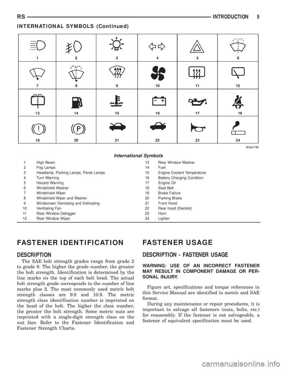
International Symbols
1 High Beam 13 Rear Window Washer
2 Fog Lamps 14 Fuel
3 Headlamp, Parking Lamps, Panel Lamps 15 Engine Coolant Temperature
4 Turn Warning 16 Battery Charging Condition
5 Hazard Warning 17 Engine Oil
6 Windshield Washer 18 Seat Belt
7 Windshield Wiper 19 Brake Failure
8 Windshield Wiper and Washer 20 Parking Brake
9 Windscreen Demisting and Defrosting 21 Front Hood
10 Ventilating Fan 22 Rear hood (Decklid)
11 Rear Window Defogger 23 Horn
12 Rear Window Wiper 24 Lighter
RSINTRODUCTION5
INTERNATIONAL SYMBOLS (Continued)
Page 1483 of 4284
FASTENER USAGE
DESCRIPTION
WARNING: USE OF AN INCORRECT FASTENER
MAY RESULT IN COMPONENT DAMAGE OR PER-
SONAL INJURY.
Figure art, specifications and torque references in
this Service Manual are identified in metric and SAE
format.
During any maintenance or repair procedures, it is
important to salvage all fasteners (nuts, bolts, etc.)
for reassembly. If the fastener is not salvageable, a
fastener of equivalent specification must be used.
THREADED HOLE REPAIR
DESCRIPTION
Most stripped threaded holes can be repaired using
a Helicoilt. Follow the vehicle or Helicoiltrecommen-
dations for application and repair procedures.
INTERNATIONAL VEHICLE
CONTROL & DISPLAY
SYMBOLS
DESCRIPTION
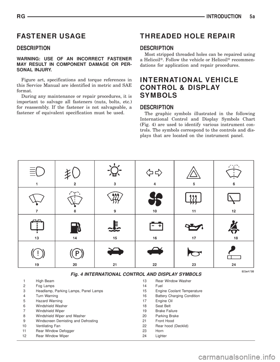
The graphic symbols illustrated in the following
International Control and Display Symbols Chart
(Fig. 4) are used to identify various instrument con-
trols. The symbols correspond to the controls and dis-
plays that are located on the instrument panel.
Fig. 4 INTERNATIONAL CONTROL AND DISPLAY SYMBOLS
1 High Beam 13 Rear Window Washer
2 Fog Lamps 14 Fuel
3 Headlamp, Parking Lamps, Panel Lamps 15 Engine Coolant Temperature
4 Turn Warning 16 Battery Charging Condition
5 Hazard Warning 17 Engine Oil
6 Windshield Washer 18 Seat Belt
7 Windshield Wiper 19 Brake Failure
8 Windshield Wiper and Washer 20 Parking Brake
9 Windscreen Demisting and Defrosting 21 Front Hood
10 Ventilating Fan 22 Rear hood (Decklid)
11 Rear Window Defogger 23 Horn
12 Rear Window Wiper 24 Lighter
RGINTRODUCTION5a
Page 1493 of 4284
Over 40 auto manufacturers world-wide have
issued and endorsed consistent gasoline specifications
(the Worldwide Fuel Charter, WWFC) to define fuel
properties necessary to deliver enhanced emissions,
performance and durability for your vehicle. We rec-
ommend the use of gasolines that meet the WWFC
specifications if they are available.
REFORMULATED GASOLINE
Many areas of the country require the use of
cleaner burning gasoline referred to as ªreformulat-
edº gasoline. Reformulated gasoline contain oxygen-
ates, and are specifically blended to reduce vehicle
emissions and improve air quality.
We strongly supports the use of reformulated gas-
oline. Properly blended reformulated gasoline will
provide excellent performance and durability for the
engine and fuel system components.
GASOLINE/OXYGENATE BLENDS
Some fuel suppliers blend unleaded gasoline with
oxygenates such as 10% ethanol, MTBE, and ETBE.
Oxygenates are required in some areas of the country
during the winter months to reduce carbon monoxide
emissions. Fuels blended with these oxygenates may
be used in your vehicle.
CAUTION: DO NOT use gasoline containing METH-
ANOL. Gasoline containing methanol may damage
critical fuel system components.
MMT IN GASOLINE
MMT is a manganese-containing metallic additive
that is blended into some gasoline to increase octane.
Gasoline blended with MMT provide no performance
advantage beyond gasoline of the same octane num-
ber without MMT. Gasoline blended with MMT
reduce spark plug life and reduce emission system
performance in some vehicles. We recommend that
gasolines free of MMT be used in your vehicle. The
MMT content of gasoline may not be indicated on the
gasoline pump; therefore, you should ask your gaso-
line retailer whether or not his/her gasoline contains
MMT.
It is even more important to look for gasoline with-
out MMT in Canada because MMT can be used at
levels higher than allowed in the United States.
MMT is prohibited in Federal and California refor-
mulated gasoline.
SULFUR IN GASOLINE
If you live in the northeast United States, your
vehicle may have been designed to meet California
low emission standards with Cleaner-Burning Cali-
fornia reformulated gasoline with low sulfur. If such
fuels are not available in states adopting Californiaemission standards, your vehicles will operate satis-
factorily on fuels meeting federal specifications, but
emission control system performance may be
adversely affected. Gasoline sold outside of California
is permitted to have higher sulfur levels which may
affect the performance of the vehicle's catalytic con-
verter. This may cause the Malfunction Indicator
Lamp (MIL), Check Engine or Service Engine Soon
light to illuminate. We recommend that you try a dif-
ferent brand of unleaded gasoline having lower sulfur
to determine if the problem is fuel related prior to
returning your vehicle to an authorized dealer for
service.
CAUTION: If the Malfunction Indicator Lamp (MIL),
Check Engine or Service Engine Soon light is flash-
ing, immediate service is required; see on-board
diagnostics system section.
MATERIALS ADDED TO FUEL
All gasoline sold in the United States and Canada
are required to contain effective detergent additives.
Use of additional detergents or other additives is not
needed under normal conditions.
FUEL SYSTEM CAUTIONS
CAUTION: Follow these guidelines to maintain your
vehicle's performance:
²The use of leaded gas is prohibited by Federal
law. Using leaded gasoline can impair engine perfor-
mance, damage the emission control system, and
could result in loss of warranty coverage.
²An out-of-tune engine, or certain fuel or ignition
malfunctions, can cause the catalytic converter to
overheat. If you notice a pungent burning odor or
some light smoke, your engine may be out of tune or
malfunctioning and may require immediate service.
Contact your dealer for service assistance.
²When pulling a heavy load or driving a fully
loaded vehicle when the humidity is low and the tem-
perature is high, use a premium unleaded fuel to
help prevent spark knock. If spark knock persists,
lighten the load, or engine piston damage may result.
²The use of fuel additives which are now being
sold as octane enhancers is not recommended. Most
of these products contain high concentrations of
methanol. Fuel system damage or vehicle perfor-
mance problems resulting from the use of such fuels
or additives is not the responsibility of Daimler-
Chrysler Corporation and may not be covered under
the new vehicle warranty.
RSLUBRICATION & MAINTENANCE0-5
FLUID TYPES (Continued)