2001 CHRYSLER VOYAGER set clock
[x] Cancel search: set clockPage 2777 of 4284
INSPECTION
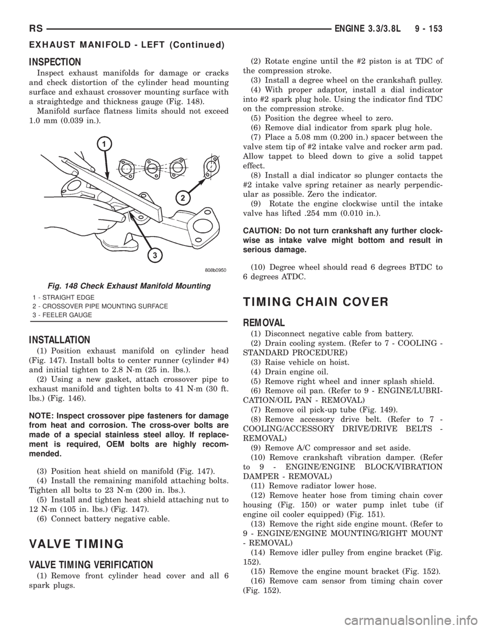
Inspect exhaust manifolds for damage or cracks
and check distortion of the cylinder head mounting
surface and exhaust crossover mounting surface with
a straightedge and thickness gauge (Fig. 148).
Manifold surface flatness limits should not exceed
1.0 mm (0.039 in.).
INSTALLATION
(1) Position exhaust manifold on cylinder head
(Fig. 147). Install bolts to center runner (cylinder #4)
and initial tighten to 2.8 N´m (25 in. lbs.).
(2) Using a new gasket, attach crossover pipe to
exhaust manifold and tighten bolts to 41 N´m (30 ft.
lbs.) (Fig. 146).
NOTE: Inspect crossover pipe fasteners for damage
from heat and corrosion. The cross-over bolts are
made of a special stainless steel alloy. If replace-
ment is required, OEM bolts are highly recom-
mended.
(3) Position heat shield on manifold (Fig. 147).
(4) Install the remaining manifold attaching bolts.
Tighten all bolts to 23 N´m (200 in. lbs.).
(5) Install and tighten heat shield attaching nut to
12 N´m (105 in. lbs.) (Fig. 147).
(6) Connect battery negative cable.
VALVE TIMING
VALVE TIMING VERIFICATION
(1) Remove front cylinder head cover and all 6
spark plugs.(2) Rotate engine until the #2 piston is at TDC of
the compression stroke.
(3) Install a degree wheel on the crankshaft pulley.
(4) With proper adaptor, install a dial indicator
into #2 spark plug hole. Using the indicator find TDC
on the compression stroke.
(5) Position the degree wheel to zero.
(6) Remove dial indicator from spark plug hole.
(7) Place a 5.08 mm (0.200 in.) spacer between the
valve stem tip of #2 intake valve and rocker arm pad.
Allow tappet to bleed down to give a solid tappet
effect.
(8) Install a dial indicator so plunger contacts the
#2 intake valve spring retainer as nearly perpendic-
ular as possible. Zero the indicator.
(9) Rotate the engine clockwise until the intake
valve has lifted .254 mm (0.010 in.).
CAUTION: Do not turn crankshaft any further clock-
wise as intake valve might bottom and result in
serious damage.
(10) Degree wheel should read 6 degrees BTDC to
6 degrees ATDC.
TIMING CHAIN COVER
REMOVAL
(1) Disconnect negative cable from battery.
(2) Drain cooling system. (Refer to 7 - COOLING -
STANDARD PROCEDURE)
(3) Raise vehicle on hoist.
(4) Drain engine oil.
(5) Remove right wheel and inner splash shield.
(6) Remove oil pan. (Refer to 9 - ENGINE/LUBRI-
CATION/OIL PAN - REMOVAL)
(7) Remove oil pick-up tube (Fig. 149).
(8) Remove accessory drive belt. (Refer to 7 -
COOLING/ACCESSORY DRIVE/DRIVE BELTS -
REMOVAL)
(9) Remove A/C compressor and set aside.
(10) Remove crankshaft vibration damper. (Refer
to 9 - ENGINE/ENGINE BLOCK/VIBRATION
DAMPER - REMOVAL)
(11) Remove radiator lower hose.
(12) Remove heater hose from timing chain cover
housing (Fig. 150) or water pump inlet tube (if
engine oil cooler equipped) (Fig. 151).
(13) Remove the right side engine mount. (Refer to
9 - ENGINE/ENGINE MOUNTING/RIGHT MOUNT
- REMOVAL)
(14) Remove idler pulley from engine bracket (Fig.
152).
(15) Remove the engine mount bracket (Fig. 152).
(16) Remove cam sensor from timing chain cover
(Fig. 152).
Fig. 148 Check Exhaust Manifold Mounting
1 - STRAIGHT EDGE
2 - CROSSOVER PIPE MOUNTING SURFACE
3 - FEELER GAUGE
RSENGINE 3.3/3.8L9 - 153
EXHAUST MANIFOLD - LEFT (Continued)
Page 3095 of 4284
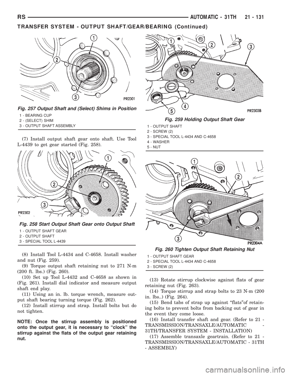
(7) Install output shaft gear onto shaft. Use Tool
L-4439 to get gear started (Fig. 258).
(8) Install Tool L-4434 and C-4658. Install washer
and nut (Fig. 259).
(9) Torque output shaft retaining nut to 271 N´m
(200 ft. lbs.) (Fig. 260).
(10) Set up Tool L-4432 and C-4658 as shown in
(Fig. 261). Install dial indicator and measure output
shaft end play.
(11) Using an in. lb. torque wrench, measure out-
put shaft bearing turning torque (Fig. 262).
(12) Install stirrup and strap. Install bolts but do
not tighten.
NOTE: Once the stirrup assembly is positioned
onto the output gear, it is necessary to ªclockº the
stirrup against the flats of the output gear retaining
nut.(13) Rotate stirrup clockwise against flats of gear
retaining nut (Fig. 263).
(14) Torque stirrup and strap bolts to 23 N´m (200
in. lbs..) (Fig. 264).
(15) Bend tabs of strap up against ªflatsºof retain-
ing bolts to prevent bolts from backing out of gear in
the event they come loose.
(16) Install transfer shaft and gear. (Refer to 21 -
TRANSMISSION/TRANSAXLE/AUTOMATIC -
31TH/TRANSFER SYSTEM - INSTALLATION)
(17) Assemble transaxle geartrain. (Refer to 21 -
TRANSMISSION/TRANSAXLE/AUTOMATIC - 31TH
- ASSEMBLY)
Fig. 257 Output Shaft and (Select) Shims in Position
1 - BEARING CUP
2 - (SELECT) SHIM
3 - OUTPUT SHAFT ASSEMBLY
Fig. 258 Start Output Shaft Gear onto Output Shaft
1 - OUTPUT SHAFT GEAR
2 - OUTPUT SHAFT
3 - SPECIAL TOOL L-4439
Fig. 259 Holding Output Shaft Gear
1 - OUTPUT SHAFT
2 - SCREW (2)
3 - SPECIAL TOOL L-4434 AND C-4658
4 - WASHER
5 - NUT
Fig. 260 Tighten Output Shaft Retaining Nut
1 - OUTPUT SHAFT GEAR
2 - SPECIAL TOOL L-4434 AND C-4658
3 - SCREW (2)
RSAUTOMATIC - 31TH21 - 131
TRANSFER SYSTEM - OUTPUT SHAFT/GEAR/BEARING (Continued)
Page 3105 of 4284
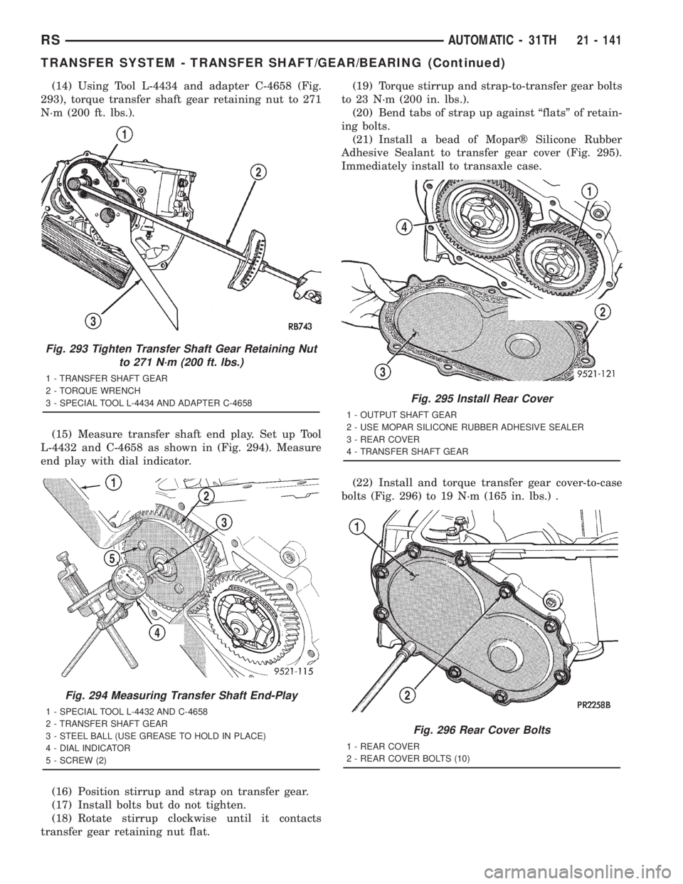
(14) Using Tool L-4434 and adapter C-4658 (Fig.
293), torque transfer shaft gear retaining nut to 271
N´m (200 ft. lbs.).
(15) Measure transfer shaft end play. Set up Tool
L-4432 and C-4658 as shown in (Fig. 294). Measure
end play with dial indicator.
(16) Position stirrup and strap on transfer gear.
(17) Install bolts but do not tighten.
(18) Rotate stirrup clockwise until it contacts
transfer gear retaining nut flat.(19) Torque stirrup and strap-to-transfer gear bolts
to 23 N´m (200 in. lbs.).
(20) Bend tabs of strap up against ªflatsº of retain-
ing bolts.
(21) Install a bead of Moparž Silicone Rubber
Adhesive Sealant to transfer gear cover (Fig. 295).
Immediately install to transaxle case.
(22) Install and torque transfer gear cover-to-case
bolts (Fig. 296) to 19 N´m (165 in. lbs.) .
Fig. 293 Tighten Transfer Shaft Gear Retaining Nut
to 271 N´m (200 ft. lbs.)
1 - TRANSFER SHAFT GEAR
2 - TORQUE WRENCH
3 - SPECIAL TOOL L-4434 AND ADAPTER C-4658
Fig. 294 Measuring Transfer Shaft End-Play
1 - SPECIAL TOOL L-4432 AND C-4658
2 - TRANSFER SHAFT GEAR
3 - STEEL BALL (USE GREASE TO HOLD IN PLACE)
4 - DIAL INDICATOR
5 - SCREW (2)
Fig. 295 Install Rear Cover
1 - OUTPUT SHAFT GEAR
2 - USE MOPAR SILICONE RUBBER ADHESIVE SEALER
3 - REAR COVER
4 - TRANSFER SHAFT GEAR
Fig. 296 Rear Cover Bolts
1 - REAR COVER
2 - REAR COVER BOLTS (10)
RSAUTOMATIC - 31TH21 - 141
TRANSFER SYSTEM - TRANSFER SHAFT/GEAR/BEARING (Continued)
Page 3121 of 4284
HYDRAULIC CONTROL PRESSURE
ADJUSTMENTS
LINE PRESSURE
An incorrect throttle pressure setting will cause
incorrect line pressure readings even though line
pressure adjustment is correct. Always inspect and
correct throttle pressure adjustment before adjusting
the line pressure.
The approximate adjustment for line pressure is
1-5/16 inches, measured from valve body to inner
edge of adjusting nut. However, due to manufactur-
ing tolerances, the adjustment can be varied to
obtain specified line pressure.
The adjusting screw may be turned with an Allen
wrench. One complete turn of adjusting screw
changes closed throttle line pressure approximately
1-2/3 psi. Turning adjusting screw counterclockwise
increases pressure, and clockwise decreases pressure.
THROTTLE PRESSURE
Throttle pressures cannot be tested accurately;
therefore, the adjustment should be measured if a
malfunction is evident.
(1) Insert gauge pin of Tool C-3763 between the
throttle lever cam and kickdown valve.
(2) By pushing in on tool, compress kickdown
valve against its spring so throttle valve is com-
pletely bottomed inside the valve body.
(3) While compressing spring, turn throttle lever
stop screw with adapter C-4553. Turn until head of
screw touches throttle lever tang, with throttle lever
cam touching tool and throttle valve bottomed. Be
sure adjustment is made with spring fully com-
pressed and valve bottomed in the valve body.
VEHICLE SPEED SENSOR/
PINION GEAR
REMOVAL
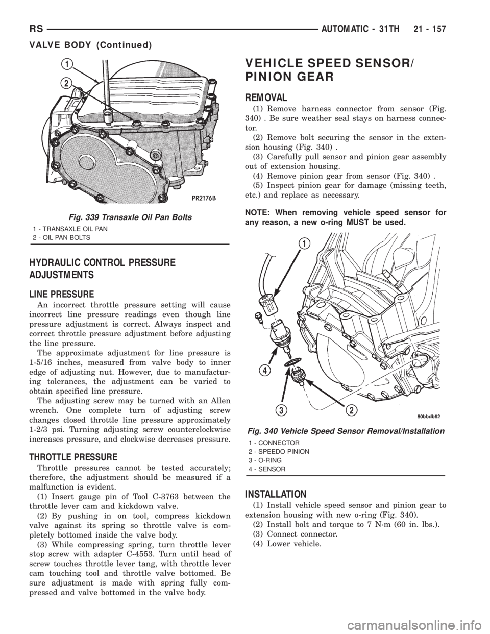
(1) Remove harness connector from sensor (Fig.
340) . Be sure weather seal stays on harness connec-
tor.
(2) Remove bolt securing the sensor in the exten-
sion housing (Fig. 340) .
(3) Carefully pull sensor and pinion gear assembly
out of extension housing.
(4) Remove pinion gear from sensor (Fig. 340) .
(5) Inspect pinion gear for damage (missing teeth,
etc.) and replace as necessary.
NOTE: When removing vehicle speed sensor for
any reason, a new o-ring MUST be used.
INSTALLATION
(1) Install vehicle speed sensor and pinion gear to
extension housing with new o-ring (Fig. 340).
(2) Install bolt and torque to 7 N´m (60 in. lbs.).
(3) Connect connector.
(4) Lower vehicle.
Fig. 339 Transaxle Oil Pan Bolts
1 - TRANSAXLE OIL PAN
2 - OIL PAN BOLTS
Fig. 340 Vehicle Speed Sensor Removal/Installation
1 - CONNECTOR
2 - SPEEDO PINION
3 - O-RING
4 - SENSOR
RSAUTOMATIC - 31TH21 - 157
VALVE BODY (Continued)
Page 3758 of 4284
LEAK DETECTION PUMP MONITOR
The leak detection assembly incorporates two pri-
mary functions: it must detect a leak in the evapora-
tive system and seal the evaporative system so the
leak detection test can be run.
The primary components within the assembly are:
A three port solenoid that activates both of the func-
tions listed above; a pump which contains a switch,
two check valves and a spring/diaphragm, a canister
vent valve (CVV) seal which contains a spring loaded
vent seal valve.
Immediately after a cold start, between predeter-
mined temperature thresholds limits, the three port
solenoid is briefly energized. This initializes the
pump by drawing air into the pump cavity and also
closes the vent seal. During non test conditions the
vent seal is held open by the pump diaphragm
assembly which pushes it open at the full travel posi-
tion. The vent seal will remain closed while the
pump is cycling due to the reed switch triggering of
the three port solenoid that prevents the diaphragm
assembly from reaching full travel. After the brief
initialization period, the solenoid is de-energized
allowing atmospheric pressure to enter the pump
cavity, thus permitting the spring to drive the dia-
phragm which forces air out of the pump cavity and
into the vent system. When the solenoid is energized
and de energized, the cycle is repeated creating flow
in typical diaphragm pump fashion. The pump is con-
trolled in 2 modes:
Pump Mode:The pump is cycled at a fixed rate to
achieve a rapid pressure build in order to shorten the
overall test length.
Test Mode:The solenoid is energized with a fixed
duration pulse. Subsequent fixed pulses occur when
the diaphragm reaches the Switch closure point.
The spring in the pump is set so that the system
will achieve an equalized pressure of about 7.5º H20.
The cycle rate of pump strokes is quite rapid as the
system begins to pump up to this pressure. As the
pressure increases, the cycle rate starts to drop off. If
there is no leak in the system, the pump would even-
tually stop pumping at the equalized pressure. If
there is a leak, it will continue to pump at a rate rep-
resentative of the flow characteristic of the size of the
leak. From this information we can determine if the
leak is larger than the required detection limit (cur-
rently set at .020º orifice by CARB). If a leak is
revealed during the leak test portion of the test, the
test is terminated at the end of the test mode and no
further system checks will be performed.
After passing the leak detection phase of the test,
system pressure is maintained by turning on the
LDP's solenoid until the purge system is activated.
Purge activation in effect creates a leak. The cycle
rate is again interrogated and when it increases dueto the flow through the purge system, the leak check
portion of the diagnostic is complete.
The canister vent valve will unseal the system
after completion of the test sequence as the pump
diaphragm assembly moves to the full travel position.
Evaporative system functionality will be verified by
using the stricter evap purge flow monitor. At an
appropriate warm idle the LDP will be energized to
seal the canister vent. The purge flow will be clocked
up from some small value in an attempt to see a
shift in the 02 control system. If fuel vapor, indicated
by a shift in the 02 control, is present the test is
passed. If not, it is assumed that the purge system is
not functioning in some respect. The LDP is again
turned off and the test is ended.
DESCRIPTION - HIGH AND LOW LIMITS
The PCM compares input signal voltages from each
input device with established high and low limits for
the device. If the input voltage is not within limits
and other criteria are met, the PCM stores a diagnos-
tic trouble code in memory. Other diagnostic trouble
code criteria might include engine RPM limits or
input voltages from other sensors or switches that
must be present before verifying a diagnostic trouble
code condition.
OPERATION - SYSTEM
The Powertrain Control Module (PCM) monitors
many different circuits in the fuel injection, ignition,
emission and engine systems. If the PCM senses a
problem with a monitored circuit often enough to
indicate an actual problem, it stores a Diagnostic
Trouble Code (DTC) in the PCM's memory. If the
code applies to a non-emissions related component or
system, and the problem is repaired or ceases to
exist, the PCM cancels the code after 40 warmup
cycles. Diagnostic trouble codes that affect vehicle
emissions illuminate the Malfunction Indicator Lamp
(MIL). Refer to Malfunction Indicator Lamp in this
section.
Certain criteria must be met before the PCM
stores a DTC in memory. The criteria may be a spe-
cific range of engine RPM, engine temperature,
and/or input voltage to the PCM.
The PCM might not store a DTC for a monitored
circuit even though a malfunction has occurred. This
may happen because one of the DTC criteria for the
circuit has not been met.For example, assume the
diagnostic trouble code criteria requires the PCM to
monitor the circuit only when the engine operates
between 750 and 2000 RPM. Suppose the sensor's
output circuit shorts to ground when engine operates
above 2400 RPM (resulting in 0 volt input to the
PCM). Because the condition happens at an engine
25 - 8 EMISSIONS CONTROLRS
EMISSIONS CONTROL (Continued)