2001 CHRYSLER VOYAGER check engine
[x] Cancel search: check enginePage 3772 of 4284
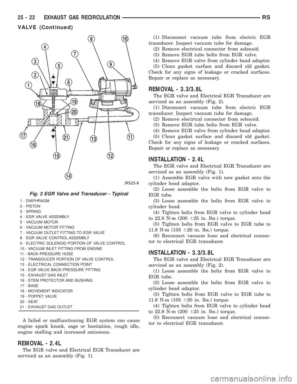
A failed or malfunctioning EGR system can cause
engine spark knock, sags or hesitation, rough idle,
engine stalling and increased emissions.
REMOVAL - 2.4L
The EGR valve and Electrical EGR Transducer are
serviced as an assembly (Fig. 1).(1) Disconnect vacuum tube from electric EGR
transducer. Inspect vacuum tube for damage.
(2) Remove electrical connector from solenoid.
(3) Remove EGR tube bolts from EGR valve.
(4) Remove EGR valve from cylinder head adaptor.
(5) Clean gasket surface and discard old gasket.
Check for any signs of leakage or cracked surfaces.
Repair or replace as necessary.
REMOVAL - 3.3/3.8L
The EGR valve and Electrical EGR Transducer are
serviced as an assembly (Fig. 2).
(1) Disconnect vacuum tube from electric EGR
transducer. Inspect vacuum tube for damage.
(2) Remove electrical connector from solenoid.
(3) Remove EGR tube bolts from EGR valve.
(4) Remove EGR valve from cylinder head adaptor.
(5) Clean gasket surface and discard old gasket.
Check for any signs of leakage or cracked surfaces.
Repair or replace as necessary.
INSTALLATION - 2.4L
The EGR valve and Electrical EGR Transducer are
serviced as an assembly (Fig. 1).
(1) Assemble EGR valve with new gasket onto the
cylinder head adaptor.
(2) Loose assemble the bolts from EGR valve to
EGR tube.
(3) Loose assemble the bolts from EGR valve to
cylinder head.
(4) Tighten bolts from EGR valve to cylinder head
to 22.8 N´m (200625 in. lbs.) torque.
(5) Tighten bolts from EGR valve to EGR tube to
11.9 N´m (105620 in. lbs.) torque.
(6) Reconnect vacuum hose and electrical connec-
tor to electrical EGR transducer.
INSTALLATION - 3.3/3.8L
The EGR valve and Electrical EGR Transducer are
serviced as an assembly (Fig. 2).
(1) Loose assemble the bolts from EGR valve to
EGR tube.
(2) Loose assemble the bolts from EGR valve to
cylinder head adaptor.
(3) Tighten bolts from EGR valve to EGR tube to
11.9 N´m (105620 in. lbs.) torque.
(4) Tighten bolts from EGR valve to cylinder head
to 22.9 N´m (200625 in. lbs.) torque.
(5) Reconnect vacuum hose and electrical connec-
tor to electrical EGR transducer.
Fig. 3 EGR Valve and Transducer - Typical
1 - DIAPHRAGM
2 - PISTON
3 - SPRING
4 - EGR VALVE ASSEMBLY
5 - VACUUM MOTOR
6 - VACUUM MOTOR FITTING
7 - VACUUM OUTLET FITTING TO EGR VALVE
8 - EGR VALVE CONTROL ASSEMBLY
9 - ELECTRIC SOLENOID PORTION OF VALVE CONTROL
10 - VACUUM INLET FITTING FROM ENGINE
11 - BACK-PRESSURE HOSE
12 - TRANSDUCER PORTION OF VALVE CONTROL
13 - ELECTRICAL CONNECTION POINT
14 - EGR VALVE BACK-PRESSURE FITTING
15 - EXHAUST GAS INLET
16 - STEM PROTECTOR AND BUSHING
17 - BASE
18 - MOVEMENT INDICATOR
19 - POPPET VALVE
20 - SEAT
21 - EXHAUST GAS OUTLET
25 - 22 EXHAUST GAS RECIRCULATIONRS
VALVE (Continued)
Page 3791 of 4284
TABLE OF CONTENTS - Continued
P0325-KNOCK SENSOR #1 CIRCUIT......................................113
P0340-NO CAM SIGNAL AT PCM.........................................116
P0351-IGNITION COIL #1 PRIMARY CIRCUIT..............................121
P0352-IGNITION COIL #2 PRIMARY CIRCUIT..............................121
P0353-IGNITION COIL #3 PRIMARY CIRCUIT..............................121
P0401 - EGR SYSTEM FAILURE.........................................124
P0403 - EGR SOLENOID CIRCUIT........................................128
P0420-1/1 CATALYTIC CONVERTER EFFICIENCY...........................131
P0441-EVAP PURGE FLOW MONITOR....................................133
P0442-EVAP LEAK MONITOR MEDIUM (.040) LEAK DETECTED...............136
P0455-EVAP LEAK MONITOR LARGE LEAK DETECTED.....................136
P0456 - EVAP LEAK MONITOR SMALL LEAK DETECTED....................136
P0443-EVAP PURGE SOLENOID CIRCUIT.................................139
P0460-FUEL LEVEL UNIT NO CHANGE OVER MILES........................142
P0462-FUEL LEVEL SENDING UNIT VOLTS TOO LOW.......................145
P0463-FUEL LEVEL SENDING UNIT VOLTS TOO HIGH......................145
P0500-NO VEHICLE SPEED SIGNAL (3SP AUTO AND MANUAL
TRANSMISSIONS).....................................................147
P0500-NO VEHICLE SPEED SIGNAL (4SP AUTO TRANS)....................150
P0505-IDLE AIR CONTROL MOTOR CIRCUITS.............................153
P0508 - IAC MOTOR SENSE CIRCUIT LOW................................156
P0509 - IAC MOTOR SENSE CIRCUIT HIGH...............................159
P0700-EATX CONTROLLER DTC PRESENT................................161
P0703-BRAKE SWITCH SENSE CIRCUIT..................................162
P0740-TORQ CONV CLU, NO RPM DROP AT LOCKUP (3SP AUTO TRANS).....165
P0743-TORQUE CONVERTER CLUTCH SOLENOID/TRANS RELAY CIRCUITS
(3SP AUTO TRANS)....................................................168
P0833-CLUTCH RELEASED SWITCH CIRCUIT.............................171
P1192-INLET AIR TEMP SENSOR VOLTAGE LOW...........................174
P1193-INLET AIR TEMP SENSOR VOLTAGE HIGH..........................176
P1195-1/1 O2 SENSOR SLOW DURING CATALYST MONITOR................178
P1281-ENGINE IS COLD TOO LONG......................................180
P1282-FUEL PUMP RELAY CONTROL CIRCUIT.............................181
P1294-TARGET IDLE NOT REACHED (2.4L)................................184
P1294-TARGET IDLE NOT REACHED (3.3L/3.8L)............................187
P1297-NO CHANGE IN MAP FROM START TO RUN.........................189
P1299-VACUUM LEAK FOUND (IAC FULLY SEATED)........................193
P1388-AUTO SHUTDOWN RELAY CONTROL CIRCUIT.......................195
P1389-NO ASD RELAY OUTPUT VOLTAGE AT PCM.........................198
P1391-INTERMITTENT LOSS OF CMP OR CKP.............................201
P1398-MIS-FIRE ADAPTIVE NUMERATOR AT LIMIT.........................205
P1486-EVAP LEAK MONITOR PINCHED HOSE FOUND......................207
P1491-RAD FAN CONTROL RELAY CIRCUIT...............................210
P1494-LEAK DETECT PUMP SW OR MECHANICAL FAULT...................214
P1495-LEAK DETECTION PUMP SOLENOID CIRCUIT.......................216
P1496-5 VOLT SUPPLY, OUTPUT TOO LOW...............................218
P1602-PCM NOT PROGRAMMED........................................221
P1899-P/N SWITCH STUCK IN PARK OR IN GEAR (3SP AUTO TRANS)........222
P1899-P/N SWITCH STUCK IN PARK OR IN GEAR (4SP AUTO TRNAS)........224
*CHECKING ECT SENSOR..............................................226
*CHECKING FUEL DELIVERY............................................227
*CHECKING IAC MOTOR (2.4L)..........................................231
*CHECKING IAT SENSOR...............................................232
iii
Page 3792 of 4284
TABLE OF CONTENTS - Continued
*CHECKING MAP SENSOR..............................................233
*CHECKING PCM POWER AND GROUND CIRCUITS........................234
*CHECKING RADIATOR FAN RELAY OUTPUT..............................235
*CHECKING THE A/C RELAY OUTPUT....................................236
*CHECKING TP SENSOR...............................................238
HEATING & A/C
P0645-A/C CLUTCH RELAY CKT.........................................239
P1598-A/C PRESSURE SENSOR VOLTS TOO HIGH.........................242
P1599-A/C PRESSURE SENSOR VOLTS TOO LOW.........................245
SPEED CONTROL
P1595-SPEED CONTROL SOLENOID CIRCUITS............................248
P1683-SPD CTRL PWR RELAY; OR S/C 12V DRIVER CKT...................248
STARTING
*ENGINE CRANKS DOES NOT START....................................253
*NO CRANK CONDITION................................................258
*NO RESPONSE FROM PCM WITH A NO START CONDITION................261
*START AND STALL CONDITION.........................................262
VEHICLE THEFT/SECURITY
ANTENNA FAILURE....................................................266
COP FAILURE.........................................................266
EEPROM FAILURE.....................................................266
INTERNAL FAULT......................................................266
RAM FAILURE.........................................................266
SERIAL LINK INTERNAL FAULT..........................................266
STACK OVERFLOW FAILURE............................................266
PCM STATUS FAILURE.................................................268
SERIAL LINK EXTERNAL FAULT.........................................268
ROLLING CODE FAILURE...............................................270
TRANSPONDER COMMUNICATION FAILURE..............................272
TRANSPONDER CYCLIC REDUNDANCY CHECK (CRC) FAILURE.............272
TRANSPONDER ID MISMATCH..........................................272
TRANSPONDER RESPONSE MISMATCH..................................272
VERIFICATION TESTS
VERIFICATION TESTS..................................................275
8.0 COMPONENT LOCATIONS..............................................283
8.1CONTROL MODULES AND FUSE & RELAY CENTER...................283
8.2CONTROLS AND SOLENOID.......................................283
8.3DATA LINK CONNECTOR..........................................285
8.4SENSORS.......................................................286
8.5FUEL SYSTEM...................................................288
8.6SWITCHES......................................................289
9.0 CONNECTOR PINOUTS................................................291
A/C COMPRESSOR CLUTCH - LT. GRAY 2 WAY............................291
A/C PRESSURE TRANSDUCER - GRAY 4 WAY.............................291
AIR TEMPERATRUE SENSOR - BLACK 2 WAY.............................291
iv
Page 3797 of 4284
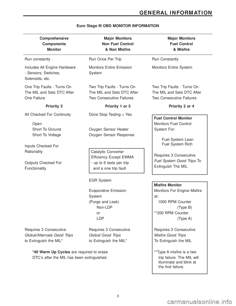
Euro Stage III OBD MONITOR INFORMATION
Comprehensive Major Monitors Major Monitors
Components Non Fuel Control Fuel Control
Monitor & Non Misfire & Misfire
Run constantly Run Once Per Trip Run Constantly
Includes All Engine Hardware Monitors Entire Emission Monitors Entire System
- Sensors, Switches, System
Solenoids, etc.
One Trip Faults - Turns On Two Trip Faults - Turns On Two Trip Faults - Turns On
The MIL and Sets DTC After The MIL and Sets DTC After The MIL and Sets DTC After
One Failure Two Consecutive Failures Two Consecutive Failures
Priority 3 Priority 1 or 3 Priority 2 or 4
All Checked For Continuity Done Stop Testing = Yes
Fuel Control Monitor
Open Monitors Fuel Control
Short To Ground Oxygen Sensor Heater System For:
Short To Voltage Oxygen Sensor Response
Fuel System Lean
Fuel System Rich
Inputs Checked For
Requires 3 Consecutive Rationality
Catalytic Converter
Fuel System Good TripsTo Efficiency Except EWMA
Extinguish The MIL Outputs Checked For - up to 6 tests per trip
Functionality and a one trip fault
EGR System
Misfire Monitor
Evaporative Emission Monitors For Engine Misfire
System at:
(Purge and Leak) 1000 RPM Counter
Non-LDP (Type B)
or **200 RPM Counter
LDP (Type A)
Requires 3 Consecutive Requires 3 Consecutive Requires 3 Consecutive
Global/Alternate Good Trips Global Good Trips Misfire Good Trips
to Extinguish the MIL* to Extinguish the MIL* To Extinguish the MIL
*40 Warm Up Cyclesare required to erase **Type A misfire is a two
DTC's
afterthe MIL has been extinguished. trip failure. The MIL will
illuminate and blink at
the first failure.
3
GENERAL INFORMATION
Page 3800 of 4284
message the PCM will terminate engine operation,
or allow the engine to continue to operate.
3.2.7 SKIM ON-BOARD DIAGNOSTICS
The SKIM has been programmed to transmit and
monitor many different coded messages as well as
PCI Bus messages. This monitoring is called On
Board Diagnosis.
Certain criteria must be met for a diagnostic
trouble code to be entered into the SKIM memory.
The criteria may be a range of; Input voltage, PCI
Bus message, or coded messages to the SKIM. If all
of the criteria for monitoring a circuit or function
are met and a fault is sensed, a diagnostic trouble
code will be stored in the SKIM memory.
3.2.8 SKIS OPERATION
When ignition power is supplied to the SKIM, the
SKIM performs an internal self-test. After the self-
test is completed, the SKIM energizes the antenna
(this activates the transponder chip) and sends a
challenge to the transponder chip. The transponder
chip responds to the challenge by generating an
encrypted response message using the following:
Secret Key -This is an electronically stored
value (identification number) that is unique to each
SKIS. The secret key is stored in the SKIM, PCM
and all ignition key transponders.
Challenge- This is a random number that is
generated by the SKIM at each ignition key cycle.
The secret key and challenge are the two vari-
ables used in the algorithm that produces the
encrypted response message. The transponder uses
the crypto algorithm to receive, decode and respond
to the message sent by the SKIM. After responding
to the coded message, the transponder sends a
transponder I.D. message to the SKIM. The SKIM
compares the transponder I.D. to the available valid
key codes in the SKIM memory (8 key maximum at
any one time). After validating the key ignition the
SKIM sends a PCI Bus message called a Seed
Request to the engine controller then waits for a
PCM response. If the PCM does not respond, the
SKIM will send the seed request again. After three
failed attempts the SKIM will stop sending the seed
request and store a trouble code. If the PCM sends
a seed response, the SKIM sends a valid/invalid key
message to the PCM. This is an encrypted message
that is generated using the following:
VIN -Vehicle Identification Number
Seed -This is a random number that is generated
by the PCM at each ignition key cycle.
The VIN and seed are the two variables used in
the rolling code algorithm that encrypts the valid/
invalid key message. The PCM uses the rolling code
algorithm to receive, decode and respond to the
valid/invalid key message sent by the SKIM. Aftersending the valid/invalid key message the SKIM
waits 3.5 seconds for a PCM status message from
the PCM. If the PCM does not respond with a valid
key message to the SKIM, a fault is detected and a
trouble code is stored.
The SKIS incorporates a VTSS LED located on
the instrument panel upper cover. The LED re-
ceives switched ignition voltage and is hardwired to
the body control module. The LED is actuated when
the SKIM sends a PCI Bus message to the body
controller requesting the LED on. The body control-
ler then provides the ground for the LED. The
SKIM will request VTSS LED operation for the
following:
± bulb checks at ignition on
± to alert the vehicle operator to a SKIS mal-
function
± customer key programming mode
For all faults except transponder faults and VTSS
LED remains on steady. In the event of a transpon-
der fault the LED flashes at a rate of 1 Hz (once per
second). If a fault is present the LED will remain on
or flashing for the complete ignition cycle. If a fault
is stored in SKIM memory which prevents the
system from operating properly, the PCM will allow
the engine to start and run (for 2 seconds) up to six
times. After the sixth attempt, the PCM disables
the starter relay until the fault is corrected.
3.2.9 PROGRAMMING THE POWERTRAIN
CONTROL MODULE
Important Note:Before replacing the PCM for a
failed driver, control circuit or ground circuit, be
sure to check the related component/circuit integ-
rity for failures not detected due to a double fault in
the circuit. Most PCM driver/control circuit failures
are caused by internal failure to components (i.e.
12-volt pull-ups, drivers and ground sensors). These
failures are difficult to detect when a double fault
has occurred and only one DTC has set.
NOTE: IF THE PCM AND THE SKIM ARE
REPLACED AT THE SAME TIME, PROGRAM
THE VIN INTO THE PCM FIRST. ALL VEHICLE
KEYS WILL THEN NEED TO BE REPLACED
AND PROGRAMMED TO THE NEW SKIM.
The SKIS Secret Key is an I.D. code that is
unique to each SKIS. This code is programmed and
stored in the SKIM, engine controller and transpon-
der chip (ignition key). When replacing the PCM it
is necessary to program the secret key into the
PCM.
1. Turn the ignition on (transmission in park/
neutral).
2. Use the DRB and select THEFT ALARM, SKIM
then MISCELLANEOUS.
6
GENERAL INFORMATION
Page 3804 of 4284
SYMPTOM DIAGNOSTIC TEST
POOR FUEL ECONOMY CHECKING PCM POWER AND GND CKT
CHECKING THE FUEL PRESSURE
CHECKING ECT SENSOR
CHECKING THROTTLE POSITION SENSOR
CHECKING MAP SENSOR
CHECKING IDLE AIR CONTROL MOTOR OPERATION
CHECKING IAT SENSOR
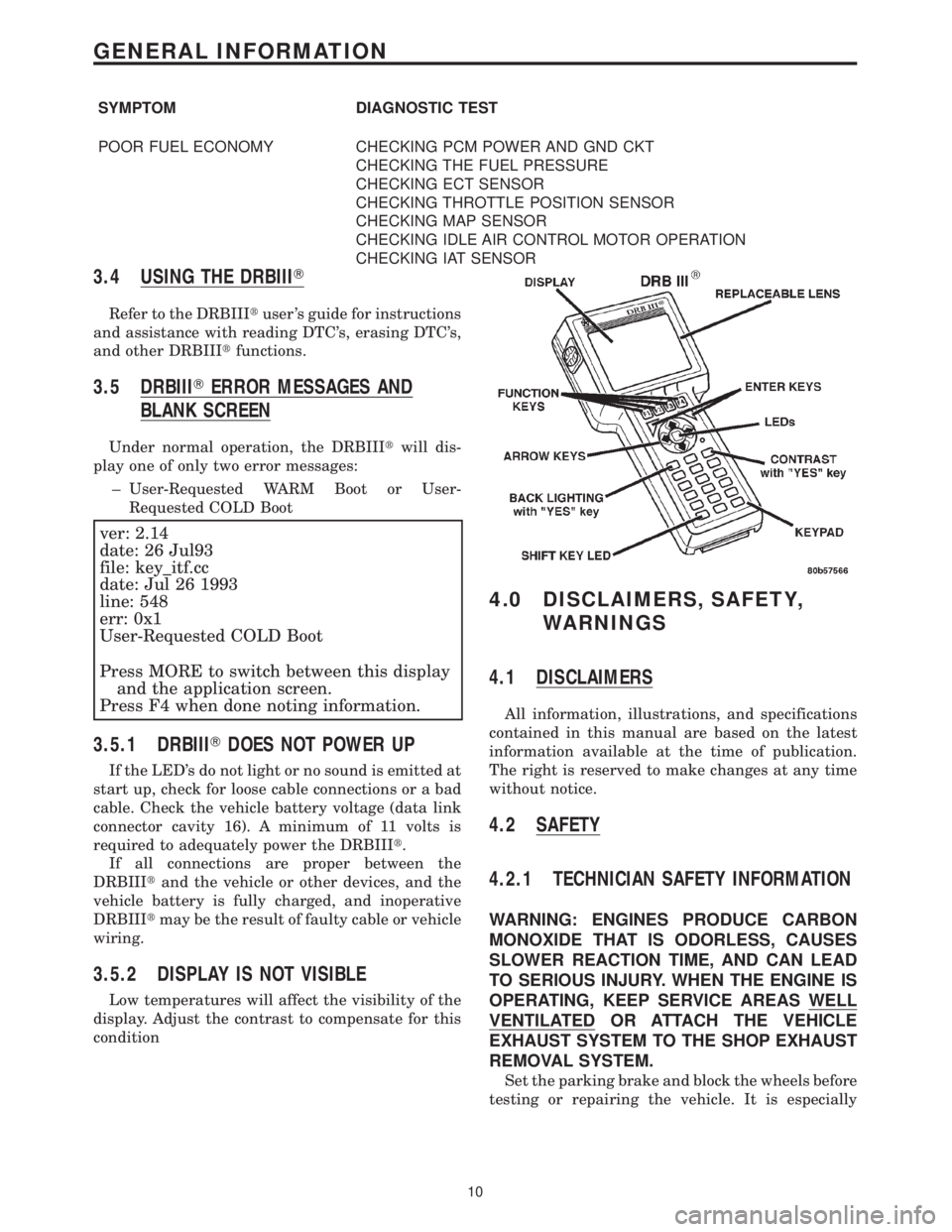
3.4 USING THE DRBIIIT
Refer to the DRBIIItuser 's guide for instructions
and assistance with reading DTC's, erasing DTC's,
and other DRBIIItfunctions.
3.5 DRBIIITERROR MESSAGES AND
BLANK SCREEN
Under normal operation, the DRBIIItwill dis-
play one of only two error messages:
± User-Requested WARM Boot or User-
Requested COLD Boot
ver: 2.14
date: 26 Jul93
file: key_itf.cc
date: Jul 26 1993
line: 548
err: 0x1
User-Requested COLD Boot
Press MORE to switch between this display
and the application screen.
Press F4 when done noting information.
3.5.1 DRBIIITDOES NOT POWER UP
If the LED's do not light or no sound is emitted at
start up, check for loose cable connections or a bad
cable. Check the vehicle battery voltage (data link
connector cavity 16). A minimum of 11 volts is
required to adequately power the DRBIIIt.
If all connections are proper between the
DRBIIItand the vehicle or other devices, and the
vehicle battery is fully charged, and inoperative
DRBIIItmay be the result of faulty cable or vehicle
wiring.
3.5.2 DISPLAY IS NOT VISIBLE
Low temperatures will affect the visibility of the
display. Adjust the contrast to compensate for this
condition
4.0 DISCLAIMERS, SAFETY,
WARNINGS
4.1 DISCLAIMERS
All information, illustrations, and specifications
contained in this manual are based on the latest
information available at the time of publication.
The right is reserved to make changes at any time
without notice.
4.2 SAFETY
4.2.1 TECHNICIAN SAFETY INFORMATION
WARNING: ENGINES PRODUCE CARBON
MONOXIDE THAT IS ODORLESS, CAUSES
SLOWER REACTION TIME, AND CAN LEAD
TO SERIOUS INJURY. WHEN THE ENGINE IS
OPERATING, KEEP SERVICE AREAS WELL
VENTILATED OR ATTACH THE VEHICLE
EXHAUST SYSTEM TO THE SHOP EXHAUST
REMOVAL SYSTEM.
Set the parking brake and block the wheels before
testing or repairing the vehicle. It is especially
10
GENERAL INFORMATION
Page 3812 of 4284
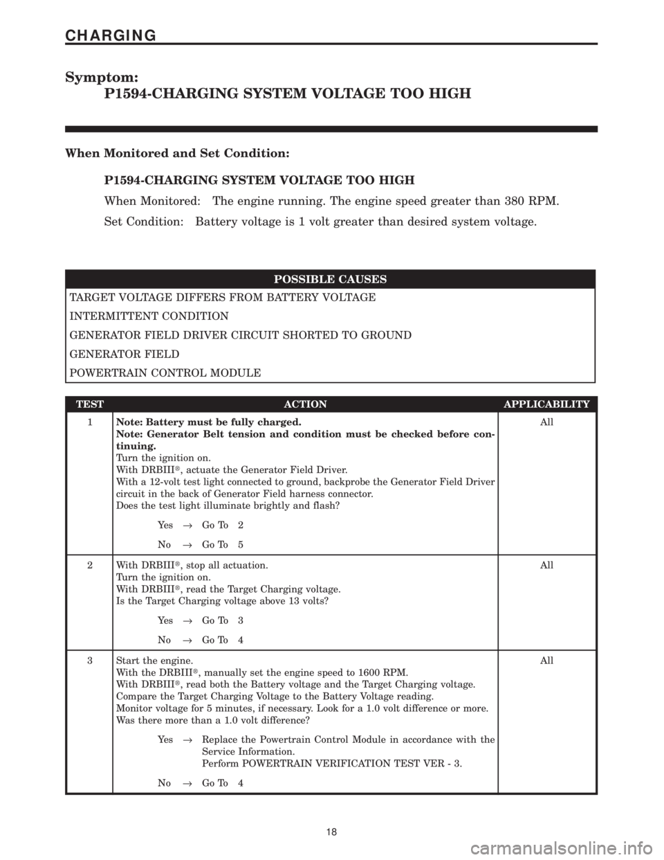
Symptom:
P1594-CHARGING SYSTEM VOLTAGE TOO HIGH
When Monitored and Set Condition:
P1594-CHARGING SYSTEM VOLTAGE TOO HIGH
When Monitored: The engine running. The engine speed greater than 380 RPM.
Set Condition: Battery voltage is 1 volt greater than desired system voltage.
POSSIBLE CAUSES
TARGET VOLTAGE DIFFERS FROM BATTERY VOLTAGE
INTERMITTENT CONDITION
GENERATOR FIELD DRIVER CIRCUIT SHORTED TO GROUND
GENERATOR FIELD
POWERTRAIN CONTROL MODULE
TEST ACTION APPLICABILITY
1Note: Battery must be fully charged.
Note: Generator Belt tension and condition must be checked before con-
tinuing.
Turn the ignition on.
With DRBIIIt, actuate the Generator Field Driver.
With a 12-volt test light connected to ground, backprobe the Generator Field Driver
circuit in the back of Generator Field harness connector.
Does the test light illuminate brightly and flash?All
Ye s®Go To 2
No®Go To 5
2 With DRBIIIt, stop all actuation.
Turn the ignition on.
With DRBIIIt, read the Target Charging voltage.
Is the Target Charging voltage above 13 volts?All
Ye s®Go To 3
No®Go To 4
3 Start the engine.
With the DRBIIIt, manually set the engine speed to 1600 RPM.
With DRBIIIt, read both the Battery voltage and the Target Charging voltage.
Compare the Target Charging Voltage to the Battery Voltage reading.
Monitor voltage for 5 minutes, if necessary. Look for a 1.0 volt difference or more.
Was there more than a 1.0 volt difference?All
Ye s®Replace the Powertrain Control Module in accordance with the
Service Information.
Perform POWERTRAIN VERIFICATION TEST VER - 3.
No®Go To 4
18
CHARGING
Page 3814 of 4284
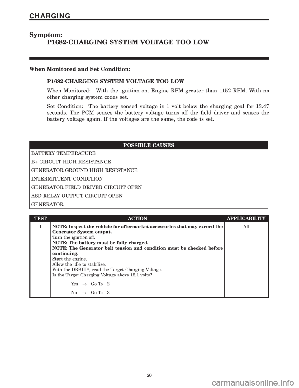
Symptom:
P1682-CHARGING SYSTEM VOLTAGE TOO LOW
When Monitored and Set Condition:
P1682-CHARGING SYSTEM VOLTAGE TOO LOW
When Monitored: With the ignition on. Engine RPM greater than 1152 RPM. With no
other charging system codes set.
Set Condition: The battery sensed voltage is 1 volt below the charging goal for 13.47
seconds. The PCM senses the battery voltage turns off the field driver and senses the
battery voltage again. If the voltages are the same, the code is set.
POSSIBLE CAUSES
BATTERY TEMPERATURE
B+ CIRCUIT HIGH RESISTANCE
GENERATOR GROUND HIGH RESISTANCE
INTERMITTENT CONDITION
GENERATOR FIELD DRIVER CIRCUIT OPEN
ASD RELAY OUTPUT CIRCUIT OPEN
GENERATOR
TEST ACTION APPLICABILITY
1NOTE: Inspect the vehicle for aftermarket accessories that may exceed the
Generator System output.
Turn the ignition off.
NOTE: The battery must be fully charged.
NOTE: The Generator belt tension and condition must be checked before
continuing.
Start the engine.
Allow the idle to stabilize.
With the DRBIIIt, read the Target Charging Voltage.
Is the Target Charging Voltage above 15.1 volts?All
Ye s®Go To 2
No®Go To 3
20
CHARGING