2001 CHRYSLER VOYAGER ESP
[x] Cancel search: ESPPage 3800 of 4284
message the PCM will terminate engine operation,
or allow the engine to continue to operate.
3.2.7 SKIM ON-BOARD DIAGNOSTICS
The SKIM has been programmed to transmit and
monitor many different coded messages as well as
PCI Bus messages. This monitoring is called On
Board Diagnosis.
Certain criteria must be met for a diagnostic
trouble code to be entered into the SKIM memory.
The criteria may be a range of; Input voltage, PCI
Bus message, or coded messages to the SKIM. If all
of the criteria for monitoring a circuit or function
are met and a fault is sensed, a diagnostic trouble
code will be stored in the SKIM memory.
3.2.8 SKIS OPERATION
When ignition power is supplied to the SKIM, the
SKIM performs an internal self-test. After the self-
test is completed, the SKIM energizes the antenna
(this activates the transponder chip) and sends a
challenge to the transponder chip. The transponder
chip responds to the challenge by generating an
encrypted response message using the following:
Secret Key -This is an electronically stored
value (identification number) that is unique to each
SKIS. The secret key is stored in the SKIM, PCM
and all ignition key transponders.
Challenge- This is a random number that is
generated by the SKIM at each ignition key cycle.
The secret key and challenge are the two vari-
ables used in the algorithm that produces the
encrypted response message. The transponder uses
the crypto algorithm to receive, decode and respond
to the message sent by the SKIM. After responding
to the coded message, the transponder sends a
transponder I.D. message to the SKIM. The SKIM
compares the transponder I.D. to the available valid
key codes in the SKIM memory (8 key maximum at
any one time). After validating the key ignition the
SKIM sends a PCI Bus message called a Seed
Request to the engine controller then waits for a
PCM response. If the PCM does not respond, the
SKIM will send the seed request again. After three
failed attempts the SKIM will stop sending the seed
request and store a trouble code. If the PCM sends
a seed response, the SKIM sends a valid/invalid key
message to the PCM. This is an encrypted message
that is generated using the following:
VIN -Vehicle Identification Number
Seed -This is a random number that is generated
by the PCM at each ignition key cycle.
The VIN and seed are the two variables used in
the rolling code algorithm that encrypts the valid/
invalid key message. The PCM uses the rolling code
algorithm to receive, decode and respond to the
valid/invalid key message sent by the SKIM. Aftersending the valid/invalid key message the SKIM
waits 3.5 seconds for a PCM status message from
the PCM. If the PCM does not respond with a valid
key message to the SKIM, a fault is detected and a
trouble code is stored.
The SKIS incorporates a VTSS LED located on
the instrument panel upper cover. The LED re-
ceives switched ignition voltage and is hardwired to
the body control module. The LED is actuated when
the SKIM sends a PCI Bus message to the body
controller requesting the LED on. The body control-
ler then provides the ground for the LED. The
SKIM will request VTSS LED operation for the
following:
± bulb checks at ignition on
± to alert the vehicle operator to a SKIS mal-
function
± customer key programming mode
For all faults except transponder faults and VTSS
LED remains on steady. In the event of a transpon-
der fault the LED flashes at a rate of 1 Hz (once per
second). If a fault is present the LED will remain on
or flashing for the complete ignition cycle. If a fault
is stored in SKIM memory which prevents the
system from operating properly, the PCM will allow
the engine to start and run (for 2 seconds) up to six
times. After the sixth attempt, the PCM disables
the starter relay until the fault is corrected.
3.2.9 PROGRAMMING THE POWERTRAIN
CONTROL MODULE
Important Note:Before replacing the PCM for a
failed driver, control circuit or ground circuit, be
sure to check the related component/circuit integ-
rity for failures not detected due to a double fault in
the circuit. Most PCM driver/control circuit failures
are caused by internal failure to components (i.e.
12-volt pull-ups, drivers and ground sensors). These
failures are difficult to detect when a double fault
has occurred and only one DTC has set.
NOTE: IF THE PCM AND THE SKIM ARE
REPLACED AT THE SAME TIME, PROGRAM
THE VIN INTO THE PCM FIRST. ALL VEHICLE
KEYS WILL THEN NEED TO BE REPLACED
AND PROGRAMMED TO THE NEW SKIM.
The SKIS Secret Key is an I.D. code that is
unique to each SKIS. This code is programmed and
stored in the SKIM, engine controller and transpon-
der chip (ignition key). When replacing the PCM it
is necessary to program the secret key into the
PCM.
1. Turn the ignition on (transmission in park/
neutral).
2. Use the DRB and select THEFT ALARM, SKIM
then MISCELLANEOUS.
6
GENERAL INFORMATION
Page 3804 of 4284
SYMPTOM DIAGNOSTIC TEST
POOR FUEL ECONOMY CHECKING PCM POWER AND GND CKT
CHECKING THE FUEL PRESSURE
CHECKING ECT SENSOR
CHECKING THROTTLE POSITION SENSOR
CHECKING MAP SENSOR
CHECKING IDLE AIR CONTROL MOTOR OPERATION
CHECKING IAT SENSOR
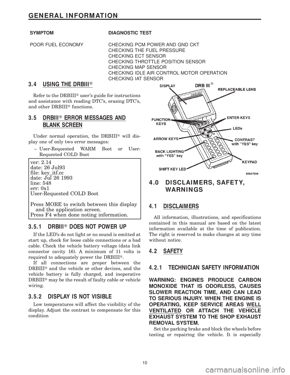
3.4 USING THE DRBIIIT
Refer to the DRBIIItuser 's guide for instructions
and assistance with reading DTC's, erasing DTC's,
and other DRBIIItfunctions.
3.5 DRBIIITERROR MESSAGES AND
BLANK SCREEN
Under normal operation, the DRBIIItwill dis-
play one of only two error messages:
± User-Requested WARM Boot or User-
Requested COLD Boot
ver: 2.14
date: 26 Jul93
file: key_itf.cc
date: Jul 26 1993
line: 548
err: 0x1
User-Requested COLD Boot
Press MORE to switch between this display
and the application screen.
Press F4 when done noting information.
3.5.1 DRBIIITDOES NOT POWER UP
If the LED's do not light or no sound is emitted at
start up, check for loose cable connections or a bad
cable. Check the vehicle battery voltage (data link
connector cavity 16). A minimum of 11 volts is
required to adequately power the DRBIIIt.
If all connections are proper between the
DRBIIItand the vehicle or other devices, and the
vehicle battery is fully charged, and inoperative
DRBIIItmay be the result of faulty cable or vehicle
wiring.
3.5.2 DISPLAY IS NOT VISIBLE
Low temperatures will affect the visibility of the
display. Adjust the contrast to compensate for this
condition
4.0 DISCLAIMERS, SAFETY,
WARNINGS
4.1 DISCLAIMERS
All information, illustrations, and specifications
contained in this manual are based on the latest
information available at the time of publication.
The right is reserved to make changes at any time
without notice.
4.2 SAFETY
4.2.1 TECHNICIAN SAFETY INFORMATION
WARNING: ENGINES PRODUCE CARBON
MONOXIDE THAT IS ODORLESS, CAUSES
SLOWER REACTION TIME, AND CAN LEAD
TO SERIOUS INJURY. WHEN THE ENGINE IS
OPERATING, KEEP SERVICE AREAS WELL
VENTILATED OR ATTACH THE VEHICLE
EXHAUST SYSTEM TO THE SHOP EXHAUST
REMOVAL SYSTEM.
Set the parking brake and block the wheels before
testing or repairing the vehicle. It is especially
10
GENERAL INFORMATION
Page 3806 of 4284
When testing voltage or continuity at any control
module, use the terminal side (not the wire end) of
the connector. Do not probe a wire through the
insulation; this will damage it and eventually cause
it to fail because of corrosion.
Be careful when performing electrical tests so as
to prevent accidental shorting of terminals. Such
mistakes can damage fuses or components. Also, a
second DTC could be set, making diagnosis of the
original problem more difficult.
5.0 REQUIRED TOOLS AND
EQUIPMENT
DRBIIIt(diagnostic read-out box) scan tool
Evaporative System Diagnostic Kit #6917
fuel filler adapter #8382
fuel pressure adapter (C-6631) or #6539
fuel pressure kit (C-4799-B) or #5069
fuel release hose (C-4799-1)
Min Air flow fitting #6714
jumper wires
ohmmeter
oscilloscope
vacuum gauge
voltmeter
12 volt test light minimum 25 ohms resistance
with probe #6801
CAUTION: A 12 VOLT TEST LIGHT SHOULD
NOT BE USED FOR THE FOLLOWING
CIRCUITS, DAMAGE TO THE POWERTRAIN
CONTROLLER WILL OCCUR.
²5 Volt Supply
²8 Volt Supply
²J1850 PCI Bus
²CCD Bus
²CKP Sensor Signal
²CMP Sensor Signal
²Vehicle Speed Sensor Signal
²O2 Sensor Signal
6.0 GLOSSARY OF TERMS
ABSanti-lock brake system
backfire,
popbackfuel ignites in either the intake or
the exhaust system
CKPcrank position sensor
CMPcamshaft position sensorcuts out,
missesa steady pulsation or the inability of
the engine to maintain a consistent
rpm
DLCdata link connector (previously
called engine diagnostic connector)
detona-
tion,
spark
knocka mild to severe ping, especially un-
der loaded engine conditions
ECTengine coolant temperature sensor
EGRexhaust gas recirculation valve
genera-
torpreviously called alternator
hard
startThe engine takes longer than usual
to start, even though it is able to
crank normally.
hesita-
tion, sag,
stumbleThere is a momentary lack of re-
sponse when the throttle is opened.
This can occur at all vehicle speeds.
If it is severe enough, the engine
may stall.
IATintake air temperature sensor
IACidle air control motor
JTECCombined engine and transmission
control module
lack of
power,
sluggishThe engine has less than expected
power, with little or no increase in
vehicle speed when the throttle is
opened.
LDPleak detection pump
MAPmanifold absolute pressure sensor
MILmalfunction indicator lamp
MTVmanifold tuning valve
O2Soxygen sensor
PCIprogrammable communication inter-
face
PCMpowertrain control module
PCVpositive crankcase ventilation
PEPperipheral expansion port
poor fuel
economyThere is significantly less fuel mile-
age than other vehicles of the same
design ad configuration
12
GENERAL INFORMATION
Page 3807 of 4284

rough,
unstable,
or er-
ratic idle
stallingThe engine runs unevenly at idle
and causes the engine to shake if it
is severe enough. The engine idle
rpm may vary (called hunting). This
condition may cause stalling if it is
severe enough.
SBECsingle board engine controller
SKIMsentry key immobilizer module
SKISsentry key immobilizer systemstart &
stallThe engine starts but immediately
dies.
surgeengine rpm fluctuation without cor-
responding change in throttle posi-
tion sensor
TPSthrottle position sensor
TRStransmission range sensor
VSSvehicle speed sensor/signal
13
GENERAL INFORMATION
Page 3830 of 4284
Symptom:
*NO RESPONSE FROM PCM (PCI BUS)
POSSIBLE CAUSES
PCM PCI NO RESPONSE
PCI BUS CIRCUIT OPEN
POWERTRAIN CONTROL MODULE
TEST ACTION APPLICABILITY
1 Turn the ignition on.
NOTE: As soon as one or more module communicates with the DRB, answer
the question.
With the DRB, enter Body then Body Computer.
With the DRB, enter Anti-Lock Brakes.
With the DRB, enter Body then Electro/Mechanical Cluster (MIC).
With the DRB, enter Passive Restraints then Airbag.
Were you able to establish communications with any of the modules?All
Ye s®Go To 2
No®Refer to symptom PCI Bus Communication Failure in the Com-
munications category.
Perform POWERTRAIN VERIFICATION TEST VER-1.
2 With the DRB read PCM Diagnostic Trouble Codes. This is to ensure power and
grounds to the PCM are operational.
NOTE: If the DRB will not read PCM DTC's, follow the NO RESPONSE TO
PCM (SCI only) symptom path, if vehicle will start. For NO START Condi-
tions follow symptom NO RESPONSE in Starting category.
Turn the ignition off.
Disconnect the PCM C2 harness connector.
Use Scope input cable CH7058, Cable to Probe adapter CH7062, and the red and
black test probes.
Connect the scope input cable to the channel one connector on the DRB. Attach the
red and black leads and the cable to probe adapter to the scope input cable.
Select DRB Standalone.
Select lab scope.
Select Live.
Select 12 volt square wave.
Press F2 for Scope.
Press F2 and use the down arrow to set voltage range to 20 volts. Press F2 again
when complete.
Connect the Black lead to the PCM ground. Connect the Red lead to the PCI Bus
circuit in the PCM connector.
Turn the ignition on.
Observe the voltage display on the DRB Lab Scope.
Does the voltage pulse from 0 to approximately 7.5 volts?All
Ye s®Replace the Powertrain Control Module in accordance with the
Service Information.
Perform POWERTRAIN VERIFICATION TEST VER-1.
No®Repair the PCI Bus circuit for an open.
Perform POWERTRAIN VERIFICATION TEST VER-1.
36
COMMUNICATION
Page 3831 of 4284
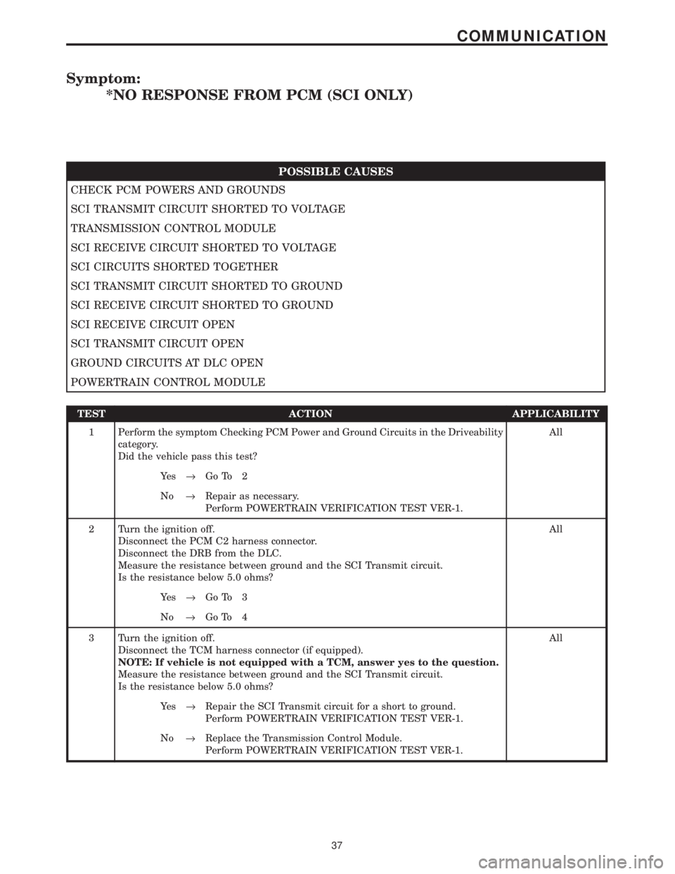
Symptom:
*NO RESPONSE FROM PCM (SCI ONLY)
POSSIBLE CAUSES
CHECK PCM POWERS AND GROUNDS
SCI TRANSMIT CIRCUIT SHORTED TO VOLTAGE
TRANSMISSION CONTROL MODULE
SCI RECEIVE CIRCUIT SHORTED TO VOLTAGE
SCI CIRCUITS SHORTED TOGETHER
SCI TRANSMIT CIRCUIT SHORTED TO GROUND
SCI RECEIVE CIRCUIT SHORTED TO GROUND
SCI RECEIVE CIRCUIT OPEN
SCI TRANSMIT CIRCUIT OPEN
GROUND CIRCUITS AT DLC OPEN
POWERTRAIN CONTROL MODULE
TEST ACTION APPLICABILITY
1 Perform the symptom Checking PCM Power and Ground Circuits in the Driveability
category.
Did the vehicle pass this test?All
Ye s®Go To 2
No®Repair as necessary.
Perform POWERTRAIN VERIFICATION TEST VER-1.
2 Turn the ignition off.
Disconnect the PCM C2 harness connector.
Disconnect the DRB from the DLC.
Measure the resistance between ground and the SCI Transmit circuit.
Is the resistance below 5.0 ohms?All
Ye s®Go To 3
No®Go To 4
3 Turn the ignition off.
Disconnect the TCM harness connector (if equipped).
NOTE: If vehicle is not equipped with a TCM, answer yes to the question.
Measure the resistance between ground and the SCI Transmit circuit.
Is the resistance below 5.0 ohms?All
Ye s®Repair the SCI Transmit circuit for a short to ground.
Perform POWERTRAIN VERIFICATION TEST VER-1.
No®Replace the Transmission Control Module.
Perform POWERTRAIN VERIFICATION TEST VER-1.
37
COMMUNICATION
Page 3832 of 4284
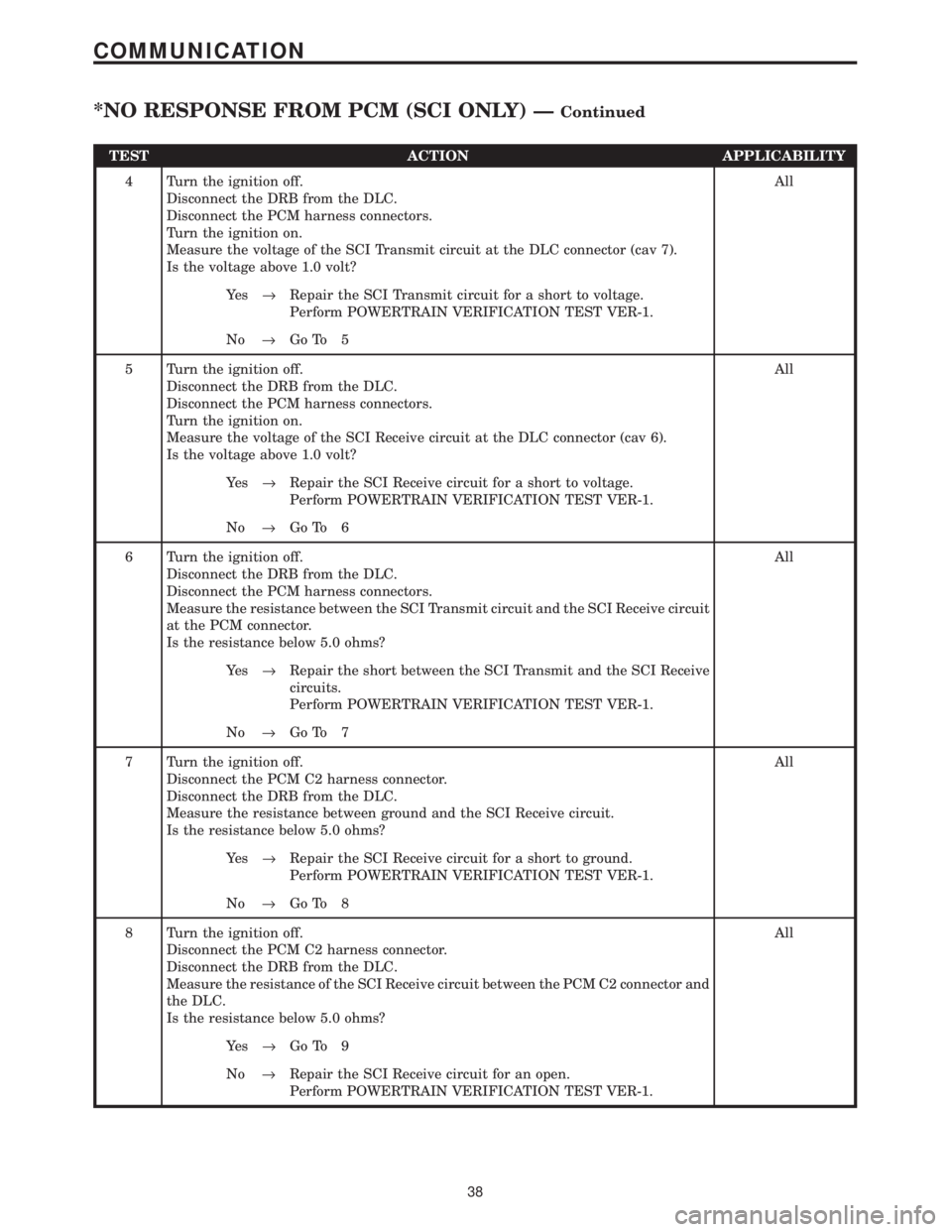
TEST ACTION APPLICABILITY
4 Turn the ignition off.
Disconnect the DRB from the DLC.
Disconnect the PCM harness connectors.
Turn the ignition on.
Measure the voltage of the SCI Transmit circuit at the DLC connector (cav 7).
Is the voltage above 1.0 volt?All
Ye s®Repair the SCI Transmit circuit for a short to voltage.
Perform POWERTRAIN VERIFICATION TEST VER-1.
No®Go To 5
5 Turn the ignition off.
Disconnect the DRB from the DLC.
Disconnect the PCM harness connectors.
Turn the ignition on.
Measure the voltage of the SCI Receive circuit at the DLC connector (cav 6).
Is the voltage above 1.0 volt?All
Ye s®Repair the SCI Receive circuit for a short to voltage.
Perform POWERTRAIN VERIFICATION TEST VER-1.
No®Go To 6
6 Turn the ignition off.
Disconnect the DRB from the DLC.
Disconnect the PCM harness connectors.
Measure the resistance between the SCI Transmit circuit and the SCI Receive circuit
at the PCM connector.
Is the resistance below 5.0 ohms?All
Ye s®Repair the short between the SCI Transmit and the SCI Receive
circuits.
Perform POWERTRAIN VERIFICATION TEST VER-1.
No®Go To 7
7 Turn the ignition off.
Disconnect the PCM C2 harness connector.
Disconnect the DRB from the DLC.
Measure the resistance between ground and the SCI Receive circuit.
Is the resistance below 5.0 ohms?All
Ye s®Repair the SCI Receive circuit for a short to ground.
Perform POWERTRAIN VERIFICATION TEST VER-1.
No®Go To 8
8 Turn the ignition off.
Disconnect the PCM C2 harness connector.
Disconnect the DRB from the DLC.
Measure the resistance of the SCI Receive circuit between the PCM C2 connector and
the DLC.
Is the resistance below 5.0 ohms?All
Ye s®Go To 9
No®Repair the SCI Receive circuit for an open.
Perform POWERTRAIN VERIFICATION TEST VER-1.
38
COMMUNICATION
*NO RESPONSE FROM PCM (SCI ONLY) ÐContinued
Page 3833 of 4284
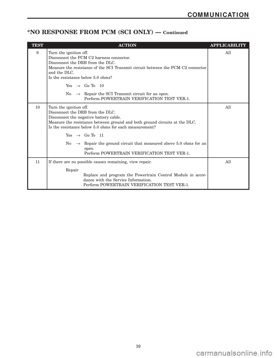
TEST ACTION APPLICABILITY
9 Turn the ignition off.
Disconnect the PCM C2 harness connector.
Disconnect the DRB from the DLC.
Measure the resistance of the SCI Transmit circuit between the PCM C2 connector
and the DLC.
Is the resistance below 5.0 ohms?All
Ye s®Go To 10
No®Repair the SCI Transmit circuit for an open.
Perform POWERTRAIN VERIFICATION TEST VER-1.
10 Turn the ignition off.
Disconnect the DRB from the DLC.
Disconnect the negative battery cable.
Measure the resistance between ground and both ground circuits at the DLC.
Is the resistance below 5.0 ohms for each measurement?All
Ye s®Go To 11
No®Repair the ground circuit that measured above 5.0 ohms for an
open.
Perform POWERTRAIN VERIFICATION TEST VER-1.
11 If there are no possible causes remaining, view repair. All
Repair
Replace and program the Powertrain Control Module in accor-
dance with the Service Information.
Perform POWERTRAIN VERIFICATION TEST VER-1.
39
COMMUNICATION
*NO RESPONSE FROM PCM (SCI ONLY) ÐContinued