2001 CHRYSLER VOYAGER ESP
[x] Cancel search: ESPPage 4055 of 4284
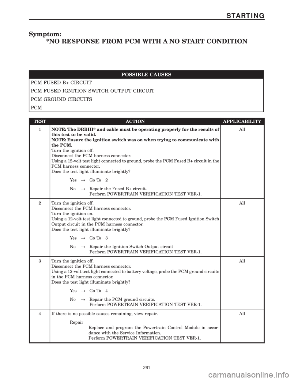
Symptom:
*NO RESPONSE FROM PCM WITH A NO START CONDITION
POSSIBLE CAUSES
PCM FUSED B+ CIRCUIT
PCM FUSED IGNITION SWITCH OUTPUT CIRCUIT
PCM GROUND CIRCUITS
PCM
TEST ACTION APPLICABILITY
1NOTE: The DRBIIItand cable must be operating properly for the results of
this test to be valid.
NOTE: Ensure the ignition switch was on when trying to communicate with
the PCM.
Turn the ignition off.
Disconnect the PCM harness connector.
Using a 12-volt test light connected to ground, probe the PCM Fused B+ circuit in the
PCM harness connector.
Does the test light illuminate brightly?All
Ye s®Go To 2
No®Repair the Fused B+ circuit.
Perform POWERTRAIN VERIFICATION TEST VER-1.
2 Turn the ignition off.
Disconnect the PCM harness connector.
Turn the ignition on.
Using a 12-volt test light connected to ground, probe the PCM Fused Ignition Switch
Output circuit in the PCM harness connector.
Does the test light illuminate brightly?All
Ye s®Go To 3
No®Repair the Ignition Switch Output circuit
Perform POWERTRAIN VERIFICATION TEST VER-1.
3 Turn the ignition off.
Disconnect the PCM harness connector.
Using a 12-volt test light connected to battery voltage, probe the PCM ground circuits
in the PCM harness connector.
Does the test light illuminate brightly?All
Ye s®Go To 4
No®Repair the PCM ground circuits.
Perform POWERTRAIN VERIFICATION TEST VER-1.
4 If there is no possible causes remaining, view repair. All
Repair
Replace and program the Powertrain Control Module in accor-
dance with the Service Information.
Perform POWERTRAIN VERIFICATION TEST VER-1.
261
STARTING
Page 4066 of 4284
Symptom List:
TRANSPONDER COMMUNICATION FAILURE
TRANSPONDER CYCLIC REDUNDANCY CHECK (CRC) FAILURE
TRANSPONDER ID MISMATCH
TRANSPONDER RESPONSE MISMATCH
Test Note: All symptoms listed above are diagnosed using the same tests.
The title for the tests will be TRANSPONDER COMMUNICA-
TION FAILURE.
When Monitored and Set Condition:
TRANSPONDER COMMUNICATION FAILURE
When Monitored: At ignition on and during Key Programming Mode.
Set Condition: When the SKIM does not receive a transponder response after 8 consec-
utive transponder read attempts within 2.0 seconds.
TRANSPONDER CYCLIC REDUNDANCY CHECK (CRC) FAILURE
When Monitored: At ignition on and during Key Programming Mode.
Set Condition: When 5 consecutive transponder signal transmissions are sent to the
SKIM with the correct message format but with invalid data.
TRANSPONDER ID MISMATCH
When Monitored: At ignition on and during Key Programming Mode.
Set Condition: When the transponder ID read by the SKIM does not match any of the
transponder ID's stored in the SKIM's memory.
TRANSPONDER RESPONSE MISMATCH
When Monitored: At ignition on and during Key Programming Mode.
Set Condition: When the transponder's crypto algorithm result fails to match the SKIM's
result.
POSSIBLE CAUSES
CHECKING MULTIPLE KEY OPERATION
SKIM
INTERMITTENT WIRING HARNESS PROBLEM
REPLACE IGNITION KEY
272
VEHICLE THEFT/SECURITY
Page 4071 of 4284
POWERTRAIN VERIFICATION TEST VER - 2 APPLICABILITY
1. NOTE: If the PCM has been replaced and the correct VIN and mileage have not
been programmed, a DTC will be set in the ABS Module, Airbag Module and the
SKIM.
2. NOTE: If the vehicle is equipped with a Sentry Key Immobilizer System, Secret
Key data must be updated. Refer to the Service Information for the PCM, SKIM and
the Transponder (ignition key) for programming information.
3. Inspect the vehicle to ensure that all components related to the repair are connected
properly.
4. With the DRBIIIt, clear DTCs and Reset Memory all engine values.
5. Run the engine for one warm-up cycle to verify proper operation.
6. Road test the vehicle. Use all accessories that may be related to this repair.
7. With the DRBIIIt, confirm that no DTC's or Secondary Indicators are present and that all
components are functioning properly.
8. If this test is being performed after a No Trouble Code test, verify the symptom is no longer
present.
9. If the symptom is still present, or any other symptom or DTC is present refer to the
appropriate category and perform the corresponding symptom.
10. Refer to any Technical Service Bulletins that may apply.
11. If there are no DTCs present and all components are functional properly, the repair is
complete.
Are any DTCs present?All
Ye s®Repair is not complete, refer to appropriate symptom.
No®Repair is complete.
POWERTRAIN VERIFICATION TEST VER - 3 APPLICABILITY
1. NOTE: If the PCM has been replaced and the correct VIN and mileage have not
been programmed, a DTC will be set in the ABS Module, Airbag Module and the
SKIM.
2. NOTE: If the vehicle is equipped with a Sentry Key Immobilizer System, Secret
Key data must be updated. Refer to the Service Information for the PCM, SKIM and
the Transponder (ignition key) for programming information.
3. Inspect the vehicle to ensure that all components related to the repair are connected
properly.
4. With the DRBIIIt, clear DTCs.
5. Perform generator output test. Refer to the appropriate service information as necessary.
6. Start the engine and set engine speed to 2000 RPM for at least thirty seconds.
7. Cycle the ignition key off and on.
8. With the DRBIIIt, read the DTCs. If the DTC returns, or any other symptom or DTC is
present, refer to the appropriate category and perform the corresponding symptom.
9. If there are no DTCs present and all components are functioning properly, the repair is
complete.
Are any DTCs present?All
Ye s®Repair is not complete, refer to appropriate symptom.
No®Repair is complete.
277
VERIFICATION TESTS
VERIFICATION TESTS ÐContinued
Page 4075 of 4284
POWERTRAIN VERIFICATION TEST VER-1 APPLICABILITY
1. NOTE: If the PCM has been replaced and the correct VIN and mileage have not
been programmed, a DTC will be set in the ABS Module, Airbag Module and the
SKIM.
2. NOTE: If the vehicle is equipped with a Sentry Key Immobilizer System, Secret
Key data must be updated. Refer to the Service Information for the PCM, SKIM and
the Transponder (ignition key) for programming information.
3. Inspect the vehicle to ensure that all components related to the repair are connected
properly.
4. Inspect the engine oil for fuel contamination. Replace the oil and filter as necessary.
5. Attempt to start the engine.
6. If the No Start condition is still present, refer to the symptom list and perform the diagnostic
testing as necessary. refer to and Technical Service Bulletins that may apply.
7. Run the engine for one warm-up cycle to verify operation.
8. With the DRBIIIt, confirm that no DTCs or Secondary Indicators are present and that all
components are functioning properly.
9. If a DTC is present, refer to the appropriate category and select the corresponding symptom.
Are any DTCs present?All
Ye s®Repair is not complete, refer to appropriate symptom.
No®Repair is complete.
SKIS VERIFICATION APPLICABILITY
1. Reconnect all previously disconnected components and connectors.
2. Obtain the vehicle's unique Personal Identification Number (PIN) assigned to it's original
SKIM. This number can be obtained from the vehicle's invoice or Chrysler's Customer Center
(1-800-992-1997).
3. NOTE: When entering the PIN, care should be taken because the SKIM will only
allow 3 consecutive attempts to enter the correct PIN. If 3 consecutive incorrect
PIN's are entered the SKIM will Lock Out the DRB III for 1 hour.
4. To exit Lock Out mode, the ignition key must remain in the Run position continually for 1
hour. Turn off all accessories and connect a battery charger if necessary.
5. With the DRB III, select Theft Alarm, SKIM and Miscellaneous. Then select desired
procedure and follow the steps that will be displayed.
6. If the SKIM has been replaced, ensure all of the vehicle ignition keys are programmed to the
new SKIM.
7. NOTE: Prior to returning vehicle to the costumer, perform a module scan to be
sure that all DTC's are erased. Erase any DTC's that are found.
8. With the DRB III erase all DTC's. Perform 5 ignition key cycles leaving the key on for at least
90 seconds per cycle.
9. With the DRB III, read the SKIM DTC's.
Are there any SKIM DTC's?All
Ye s®Repair is not complete, refer to appropriate symptom.
No®Repair is complete.
281
VERIFICATION TESTS
VERIFICATION TESTS ÐContinued
Page 4105 of 4284

1.0 INTRODUCTION
The procedures contained in this manual include
all of the specifications, instructions, and graphics
needed to diagnose 41TE/AE Electronic Automatic
Transaxle (EATX) problems. The diagnostics in this
manual are based on the failure condition or symp-
tom being present at the time of diagnosis.
When repairs are required, refer to the appropri-
ate volume of the service manual for the proper
removal and repair procedure.
Diagnostic procedures change every year. New
diagnostic systems may be added and/or carryover
systems may be enhanced. READ THIS MANUAL
BEFORE TRYING TO DIAGNOSE A VEHICLE
TROUBLE CODE. It is recommended that you
review the entire manual to become familiar with
all new and changed diagnostic procedures.
This book reflects many suggested changes from
readers of past issues. After using this book, if you
have any comments or recommendations, please fill
out the form at the back of the book and mail it back
to us.
1.1 SYSTEM COVERAGE
This diagnostic procedures manual covers all
2001 RG equipped with a 41TE/AE transaxle.
1.2 SIX -STEP TROUBLESHOOTING
PROCEDURE
Diagnosis of the 41TE/AE electronic transaxle is
done in six basic steps:
verification of complaint
verification of any related symptoms
symptom analysis
problem isolation
repair of isolated problem
verification of proper operation
2.0 IDENTIFICATION OF
SYSTEM
RG series vehicles equipped with a 4 speed trans-
mission.
3.0 SYSTEM DESCRIPTION AND
FUNCTIONAL OPERATION
3.1 GENERAL DESCRIPTION
The 41TE/AE electronic transaxle is a conven-
tional transaxle in that it uses hydraulically ap-
plied clutches to shift a planetary gear train. How-
ever, the electronic control system replaces many of
the mechanical and hydraulic components used in
conventional transmission valve bodies.
3.2 FUNCTIONAL OPERATION
The 41TE/AE electronic transaxle has a fully
adaptive control system. The system performs it's
functions based on continuous real-time sensor
feedback information. The control system automat-
ically adapts to changes in engine performance and
friction element variations to provide consistent
shift quality. The control system ensures that clutch
operation during upshifting and downshifting is
more responsive without increased harshness.
The Transmission Control Module (TCM) contin-
uously checks for electrical problems, mechanical
problems, and some hydraulic problems. When a
problem is sensed, the TCM stores a diagnostic
trouble code. Some of these codes cause the tran-
saxle to go into limp-in or default mode.
While in this mode, electrical power is taken
away from the transaxle via the TCM, de-
energizing the transmission control relay, and tak-
ing power from the solenoid pack. When this hap-
pens, the only transaxle mechanical functions are:
Park and Neutral
Reverse
Second Gear
No upshifts or downshifts are possible. The posi-
tion of the manual valve alone allows the three
ranges that are available. Although vehicle perfor-
mance is seriously degraded while in this mode, it
allows the owner to drive the vehicle in for service.
Once the DRBIIItis in the EATX portion of the
diagnostic program, it constantly monitors the
TCM to see if the system is in limp-in mode. If the
transaxle is in limp-in mode, the DRBIIIž will flash
the red LED.
3.2.1 AUTOSTICK FEATURE
This feature allows the driver to manually shift
the transaxle when the shift lever is pulled back
into the AutoStick position. When in AutoStick
mode, the instrument cluster displays the current
gear.
1
GENERAL INFORMATION
Page 4114 of 4284
responding element is applied. If a switch fails to
close, it is retested, If it fails the second test, the
code is set.
Transmission Effects:The MIL illuminates and
the transmission system defaults to Relay Open
limp-in mode.
Possible causes:
> Pressure switch sense circuit shorted to battery
between TCM and solenoid pack.
> Low line pressure
> Solenoid Pack
Name of code:P1791(35) - Loss Of Prime
When monitored:If the transmission is slipping
in any forward gear and the pressure switches are
not indicating pressure, a loss of prime test is run.
Set condition:If the transmission begins to slip in
any forward gear, and the pressure switch or
switches that should be closed for a given gear are
open, a loss of prime test begins. All available
elements (in 1st gear L-R, 2-4 and OD, in 2nd, 3rd,
and 4th gear 2-4 and OD) are turned on by the
Transmission Control Module (TCM) to see if pump
prime exists. The code is set if none of the pressure
switches respond. The TCM will continue to run the
loss of prime test until pump pressure returns.
Theory of operation:The loss of prime test is
used to prevent transmission defaults which can be
caused by a lack of pump prime.
Transmission Effects:Vehicle will not move or
transmission slips. Normal operation will continue
if pump prime returns.
Possible causes:
> Low transmission fluid level
> PRNDL indicates a valid OD code in the hydrau-
lic reverse position
> Transmission fluid filter clogged or damaged
> Transmission fluid filter improperly installed
(Bolts loose or O-ring missing)
> Oil pump - If a customer has a problem when the
transmission is cold whereby he shifts to reverse,
gets reverse, and then shifts to OD and does not
get OD (gets a neutral condition), and then can
not get reverse or OD for between 3-20 seconds,
replace the oil pump. High side clearance in the
oil pump will set a code 35. The pump will prime
upon start-up, but as the torque converter purges
air (drain down) the air will leak across the inner
rotor into the pump suction port and cause a loss
of prime right after the shift into OD. After 3- 20
seconds, pump prime will return and normal
operation will continue. The pump should be
replaced only after all other possible causes
above have been checked and verified.Name of code:P1790(36) - Fault Immediately
After Shift
When monitored:After a gear ratio error is
stored.
Set condition:This code is set if the associated
gear ratio code is stored within 1.3 seconds after a
shift.
Theory of operation:This code will only be stored
along with a 50 series code. If this code is set, it
indicates the problem is mechanical in nature.
When this code exists, diagnosing the transmission
should be based on the associated gear ratio code
and primarily mechanical causes should be consid-
ered.
Transmission Effects:None
Possible causes:
> Mechanical causes as listed under associated
gear ratio code.
Name of code:P1775(37) - Solenoid Switch Valve
Latched in TCC Position
When monitored:During an attempted shift into
1st gear.
Set condition:This code is set if three unsuccess-
ful attempts are made to get into 1st gear in one
given key start.
Theory of operation:The solenoid switch valve
(SSV) controls the direction of the transmission
fluid when the L-R/TCC solenoid is energized. The
SSV will be in the downshifted position in 1st gear,
thus directing the fluid to the L-R clutch circuit. In
2nd, 3rd, and 4th, it will be in the upshifted position
and directs the fluid into the torque converter
clutch (TCC).
When shifting into 1st gear, a special hydraulic
sequence is performed to ensure SSV movement
into the downshifted position. The L-R pressure
switch is monitored to confirm SSV movement. If
movement is not confirmed (the L-R pressure
switch does not close), 2nd gear is substituted for
1st.
Transmission Effects:Transmission will have no
1st gear (2nd gear will be substituted), and no
EMCC operation.
Possible causes:
> PRNDL indicates a valid OD code in the hydrau-
lic reverse position
> Valve body- - Solenoid valve stuck in TCC posi-
tion
> High idle speed
> Solenoid malfunction - L-R pressure switch will
not close
> L-R Pressure Switch Sense circuit shorted to
battery
10
GENERAL INFORMATION
Page 4116 of 4284
the L-R pressure switch does not indicate pressure.
A second detection of L-R pressure results in setting
the code.
Transmission Effects:At speeds above 72 Km/h
(45 MPH), EMCC is inhibited. Once speed falls
below 72 Km/h (45 MPH), the transmission will go
into relay open limp-in mode and the MIL will
illuminate.
Possible causes:
> Valve body - Solenoid valve stuck in L-R position
> Intermittent short to ground or open circuit in
L-R Pressure Switch Sense circuit (with code 24
only)
> Solenoid pack (with code P1784(24) only)
> TCM (with code P1784(24) only)
Name of Code:P1793(48) - Torque Reduction
(TRD) Link Communication Error
Note: The MIL may set on some engines (3.3L, 3.8L,
3.5L)
When Monitored:Whenever the engine is run-
ning
Set condition:This code is set when the TCM
sends multiple torque reduction messages to the
PCM and the TCM does not receive a response from
the PCM.
Theory of Operation:During high torque shifts
the TCM will send a message requesting that the
PCM reduce engine power until the shift is com-
pleted. This message is sent from the TCM to the
Powertrain Control Module across the Torque Man-
agement Request Sense Circuit. The PCM will
acknowledge the TCM request by sending a mes-
sage across the PCI bus within a specific amount of
time. The TRD Link communication is also tested
periodically for operation whenever the engine is
running and the vehicle is not moving with zero
degrees throttle.
Transmission Effects:Maximum throttle angle
used by TCM will be 54 degrees. As a result a
customer my complain about loss of performance or
of short shifting when driving aggressively.
Possible Causes:
> Sticky Throttle Position Sensor (TPS)
> Wiring or Connector problems in the Torque
Management Request Sense Circuit
> PCM
> TCM
Name of code:P0736(50) - Gear Ratio Error in
Reverse
P0731(51) - Gear Ratio Error in 1st
P0732(52) - Gear Ratio Error in 2nd
P0733(53) - Gear Ratio Error in 3rd
P0734(54) - Gear Ratio Error in 4th
P0715(56) - Input Speed Sensor Error
P0720(57) - Output Speed Sensor Error
P1794(58) - Speed Sensor Ground Error
When monitored:The transmission gear ratio is
monitored continuously while the transmission is in
gear.
Set condition:This code is set if the gear ratio is
not correct for a period of time.
± Codes 50 through 54 sets if the ratio of the
input RPM (Nt) to the output RPM (No) does
not match the given gear ratio.
± Code 56 sets if there is an excessive change in
input RPM in any gear
± Code 57 sets if there is an excessive change in
output RPM in any gear
± Code 58 sets after a TCM reset in neutral and
Nt/No equals a ratio of input to output of 2.50
A hard code sets within 3 seconds, an intermit-
tent code sets within 15 seconds.
Theory of operation:The transmission system
uses two speed sensors, one to measure input RPM
and one to measure output RPM. These inputs are
essential for proper transmission operation. There-
fore, the integrity of this data is verified through
the following checks:
1. When in gear, if the gear ratio does not compare
to a known gear ratio, the corresponding in-gear
trouble code is set (codes 50 through 54).
2. An excessive change in input or output speeds
indicating signal intermittent will result in
codes 56 and/or 57 being set.
3. After a TCM reset in neutral, observing erratic
output and input speed sensor signals indicates
a loss of the common speed sensors ground. This
sets a code 58.
Transmission Effects:The transmission will not
go into relay open limp-in mode until three gear
ratio error events occur in a given key start. This
allows for intermittent problems to correct them-
selves without opening the relay. However, if a gear
ratio error develops, a code is always set, but if the
condition corrects itself the transmission will con-
tinue without requiring the ignition key to be cycled
on and off. Many different events could occur given
the range of failures possible for codes 50 through
58. The following are a few examples:
± Codes 51, 52, 53, 54, 56, and 57 at speeds
above 72 Km/h (45 MPH) - The appropriate
code is set, EMCC is aborted and current gear
is maintained. If while still traveling above 72
Km/h (45 MPH), the gear ratio becomes valid
again, EMCC will reengage and normal oper-
ation will resume. If the gear ratio becomes
intermittent and recovers three times in a
given key start, the current gear will be main-
tained and EMCC inhibited, then the trans-
mission will go into relay open limp-in mode if
12
GENERAL INFORMATION
Page 4119 of 4284
then notice harsh bumps when the A/C clutch is
being cycled, but vehicle shudder will be elimi-
nated. After 35 OBDII (EURO STAGE III OBD)
warm-up starts or if the code is cleared, PEMCC
will be reactivated to see if shudder is still present.
If one shudder event occurs, the code will be reset.
Clearing the code and running battery disconnect
with the DRBIIItis the only way to reset the
shudder counter from 20 back to zero.
Transmission Effects:This code does not cause
the transmission to go into limp-in mode. However,
once the code is set, FEMCC to PEMCC operation
before the A/C clutch engagement will be disabled
for 35 OBDII (EURO STAGE III OBD) warm up
starts.
Possible causes:
> Degraded transmission fluid
> Wheels severely out of alignment
> Internal torque converter problem
Name of Code:P1799(74) - Calculated Oil Temper-
ature in Use
When Monitored:When ever the Engine is run-
ning.
Set condition:The code is set if any of the follow-
ing conditions exist for three consecutive key starts:
> The Temperature Sensor voltage is out of range
(below 0.07 volts or greater than 4.94 volts)
> If continuous erratic Temperature Sensor voltage
is sensed.
> The Temperature Sensor temperature stays be-
low 27C (80ÉF) for an extended period of time.
Theory of Operation:The TCM uses a Tempera-
ture Sensor to monitor the transmission sump tem-
perature. This temperature is used to determine
which shift schedule the TCM is to use. (See Trans-
mission Operation and Shift Scheduling at Various
Sump Temperatures in this diagnostic manual) If
the Temperature Sensor circuit fails to operate
properly the TCM will use the calculated oil tem-
perature routine found in prior model year TCM. If
this occurs for three consecutive key starts, the code
will be set. The TCM will then test the Temperature
Sensor circuit after every 35 OBDII (EURO STAGE
III OBD) warm-up starts. If the Temperature Sen-
sor circuit is OK, the Temperature Sensor data is
used in place of the Calculated Oil Temperature
data.
Transmission Effects:If the Temperature Sensor
indicates a temperature below -18C (0É F) or above
115C (240É F) at start up, The TCM compares the
calculated oil temperature to the indicated Temper-
ature Sensor oil temperature. If the calculated oil
temperature differs significantly from the Temper-
ature Sensor value, the calculated oil temperature
will be used for that key start.Possible Causes:
> Wiring or Connector problems in the transmis-
sion temperature sensor signal circuit.
> TRS
> TCM
Name of Code:P1738(75) - High Temperature
Operation Activated.
When Monitored:Whenever the engine is running.
Set Condition:Immediately once the Overheat
Shift Schedule is activated.
Theory of Operation:If the transmission oil tem-
perature rises above 115C (240ÉF), the overheat
shift schedule is activated refer to Transmission
Operation as a function of Transmission Oil Tem-
perature and the code is set. The DTC is an infor-
mation code only and is being set to aid the techni-
cian in determining root cause of a customer
driveability issue. The code is also intended to alert
the technician to determine if a cooling system
malfunction has occurred or if an additional trans-
mission air to oil cooler should be added to the
vehicle if the customer regularly drives in a manner
that overheats the transmission. Extended opera-
tion above 115C (240ÉF) will reduce the durability of
the transmission and should be avoided. Correcting
the cooling system malfunction or installing an
additional transmission oil cooler will improve
transmission durability especially for customers
who operate in city/construction stop and go traffic,
tow trailers regularly, drive aggressively in low gear
or drive regularly in mountainous areas.
Transmission Effects:Information only code. -
Overheat shift schedule was activated, no limp-in
condition occurs. 2nd gear partial EMCC above 40
Km/h (25 MPH), 3rd gear EMCC from 45-69 Km/h
(28-43 MPH), delayed 3-4 upshift at 69 Km/h (43
MPH), early 4-3 coastdown at 66 Km/h (41 MPH),
EMCC operation under all conditions above 40
Km/h (25 MPH) except at closed throttle or 1st gear.
Possible Causes:
± Transmission Overfilled with Oil
± Engine cooling fan failure
± Engine thermostat stuck closed
± Radiator corroded or packed with dirt
± Transmission Oil Cooler Plugged
± Customer driving pattern requires additional
transmission cooling
Name Of Code:P1739(76) - Power-Up at Speed
When Monitored:When TCM (transmission con-
trol module) initially powers-up.
Set Condition:If the TCM powers up while in the
9Drive9position and the vehicle is going above 32
Km/h (20 MPH), the code is set.
Theory of Operation:If a vehicle loses power to
the TCM, the vehicle will go to the 2nd gear mode
15
GENERAL INFORMATION