Page 3511 of 4284
UPPER WINDSHIELD FRAME/ROOF PANEL - LONG WHEEL BASE ONLY
ROOF BOWS/INNER ROOF SIDE RAILS
RSBODY23 - 131
BODY (Continued)
Page 3512 of 4284
OUTER ROOF PANEL - LONG WHEEL BASE ONLY
23 - 132 BODYRS
BODY (Continued)
Page 3516 of 4284
UPPER WINDSHIELD FRAME/OUTER ROOF PANEL - SHORT WHEEL BASE ONLY
23 - 136 BODYRS
BODY (Continued)
Page 3522 of 4284
ROOF BOWS/UPPER LIFTGATE FRAME - LONG WHEEL BASE ONLY
23 - 142 BODYRS
BODY (Continued)
Page 3528 of 4284
ROOF PANEL/ROOF RAIL - SHORT WHEEL BASE ONLY
23 - 148 BODYRS
BODY (Continued)
Page 3529 of 4284

SPECIFICATIONS -
TORQUE SPECIFICATIONS
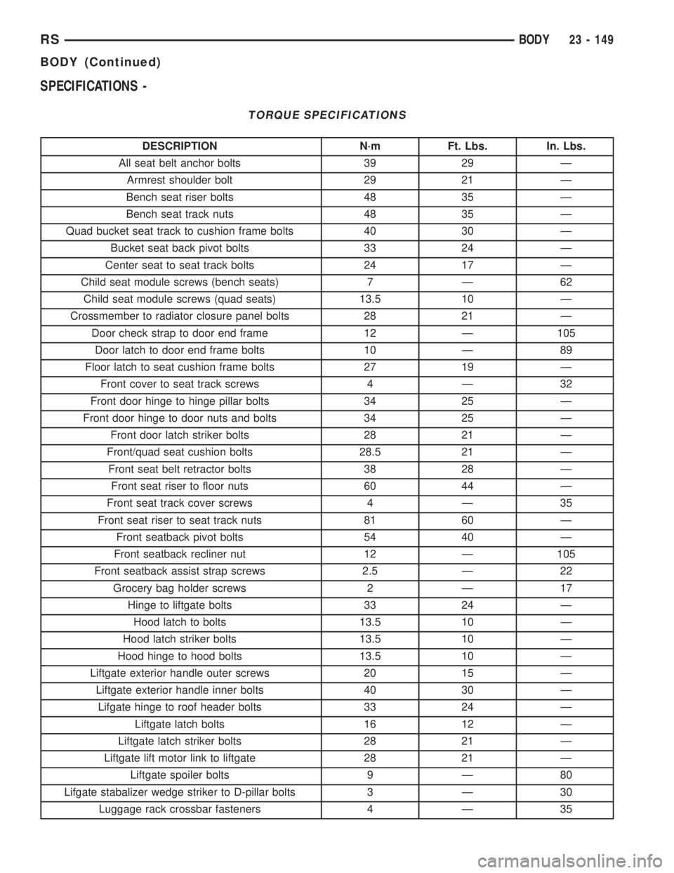
DESCRIPTION N´m Ft. Lbs. In. Lbs.
All seat belt anchor bolts 39 29 Ð
Armrest shoulder bolt 29 21 Ð
Bench seat riser bolts 48 35 Ð
Bench seat track nuts 48 35 Ð
Quad bucket seat track to cushion frame bolts 40 30 Ð
Bucket seat back pivot bolts 33 24 Ð
Center seat to seat track bolts 24 17 Ð
Child seat module screws (bench seats) 7 Ð 62
Child seat module screws (quad seats) 13.5 10 Ð
Crossmember to radiator closure panel bolts 28 21 Ð
Door check strap to door end frame 12 Ð 105
Door latch to door end frame bolts 10 Ð 89
Floor latch to seat cushion frame bolts 27 19 Ð
Front cover to seat track screws 4 Ð 32
Front door hinge to hinge pillar bolts 34 25 Ð
Front door hinge to door nuts and bolts 34 25 Ð
Front door latch striker bolts 28 21 Ð
Front/quad seat cushion bolts 28.5 21 Ð
Front seat belt retractor bolts 38 28 Ð
Front seat riser to floor nuts 60 44 Ð
Front seat track cover screws 4 Ð 35
Front seat riser to seat track nuts 81 60 Ð
Front seatback pivot bolts 54 40 Ð
Front seatback recliner nut 12 Ð 105
Front seatback assist strap screws 2.5 Ð 22
Grocery bag holder screws 2 Ð 17
Hinge to liftgate bolts 33 24 Ð
Hood latch to bolts 13.5 10 Ð
Hood latch striker bolts 13.5 10 Ð
Hood hinge to hood bolts 13.5 10 Ð
Liftgate exterior handle outer screws 20 15 Ð
Liftgate exterior handle inner bolts 40 30 Ð
Lifgate hinge to roof header bolts 33 24 Ð
Liftgate latch bolts 16 12 Ð
Liftgate latch striker bolts 28 21 Ð
Liftgate lift motor link to liftgate 28 21 Ð
Liftgate spoiler bolts 9 Ð 80
Lifgate stabalizer wedge striker to D-pillar bolts 3 Ð 30
Luggage rack crossbar fasteners 4 Ð 35
RSBODY23 - 149
BODY (Continued)
Page 3551 of 4284

(8) Install center roller channel end cover (Fig. 16).
(9) Install center stop on sliding door. (Refer to 23
- BODY/DOORS - SLIDING/STOP BUMPER -
INSTALLATION)
(10) Place upper roller stop bumper in position on
upper roller arm.
(11) Install screw to hold upper roller arm stop
bumper to upper roller arm (Fig. 14).
(12) Remove masking tape from body surfaces.
(13) Verify door operation and fit. Adjust as neces-
sary. (Refer to 23 - BODY/DOORS - SLIDING/SLID-
ING DOOR - ADJUSTMENTS)
SLIDING DOOR ADJUSTMENTS
NOTE: For power sliding door procedures refer to
POWER SLIDING DOOR SYSTEM in the ELECTRI-
CAL section.
PRELIMINARY CHECKS
(1) Close the sliding door, visually checking C-post
striker alignment entry into latch. Striker at this
point must not affect alignment. Striker should go
straight into the latching mechanism.
(2) On vehicles with left sliding doors, check the
fuel door blocker striker entry into latch. Striker at
this point must not affect alignment.
(3) Check C-post and B-post for door to aperture
gaps and door to door gaps. All gaps should be 5 mm
1 mm.
(4) Check door for height using character lines as
a reference. Also check roof contour as a controlling
factor.
Using the procedures noted below, adjust the side
door in the order the individual steps are called out.
DOOR FLUSHNESS ADJUSTMENT
(1) Check sliding door flushness at the C-pillar
striker.
(2) Adjust the C-pillar striker in or out untill the
door is flush.
(3) Check upper B-pillar flushness to A-pillar
cover.
(4) Loosen one nut on upper hinge and adjust door
in or out untill the door is flush.
(5) Check flushness at upper C-pillar.
(6) If upper C-pillar flushness is out of specifica-
tion use a heavy rubber malet on the door assembly
until door is in spec.
DOOR GAP ADJUSTMENT - UP/DOWN
UP/DOWN ADJUSTMENT
(1) Visually inspect the sliding door for fitting low
at the top of the door by checking the alignment of
the top contour of the door to the quarter panel.(2) Fully open the sliding door.
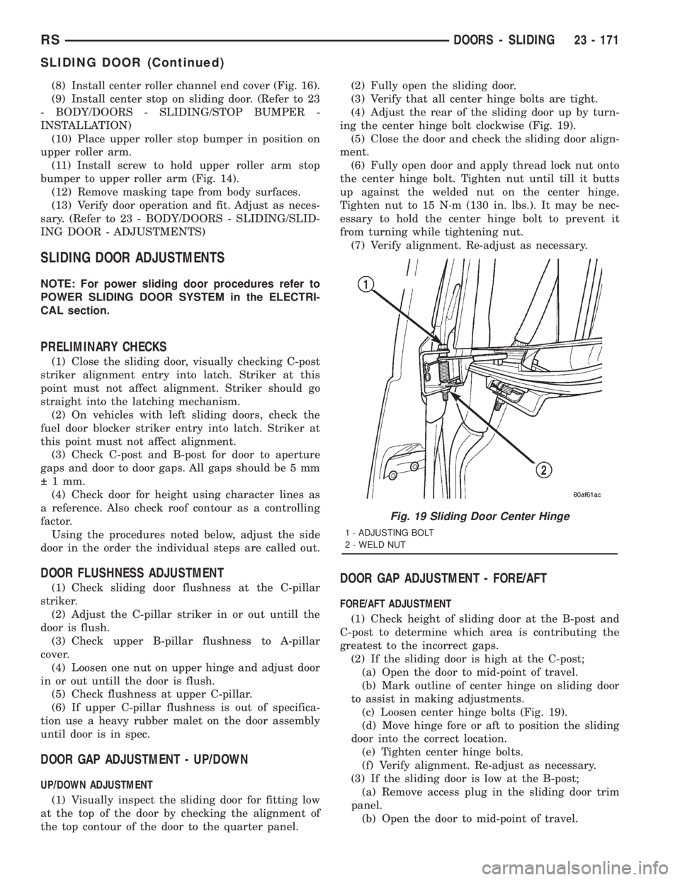
(3) Verify that all center hinge bolts are tight.
(4) Adjust the rear of the sliding door up by turn-
ing the center hinge bolt clockwise (Fig. 19).
(5) Close the door and check the sliding door align-
ment.
(6) Fully open door and apply thread lock nut onto
the center hinge bolt. Tighten nut until till it butts
up against the welded nut on the center hinge.
Tighten nut to 15 N´m (130 in. lbs.). It may be nec-
essary to hold the center hinge bolt to prevent it
from turning while tightening nut.
(7) Verify alignment. Re-adjust as necessary.
DOOR GAP ADJUSTMENT - FORE/AFT
FORE/AFT ADJUSTMENT
(1) Check height of sliding door at the B-post and
C-post to determine which area is contributing the
greatest to the incorrect gaps.
(2) If the sliding door is high at the C-post;
(a) Open the door to mid-point of travel.
(b) Mark outline of center hinge on sliding door
to assist in making adjustments.
(c) Loosen center hinge bolts (Fig. 19).
(d) Move hinge fore or aft to position the sliding
door into the correct location.
(e) Tighten center hinge bolts.
(f) Verify alignment. Re-adjust as necessary.
(3) If the sliding door is low at the B-post;
(a) Remove access plug in the sliding door trim
panel.
(b) Open the door to mid-point of travel.
Fig. 19 Sliding Door Center Hinge
1 - ADJUSTING BOLT
2 - WELD NUT
RSDOORS - SLIDING23 - 171
SLIDING DOOR (Continued)
Page 3557 of 4284

(5) Engage rigging cam to latch/lock control mech-
anism.
(6) Move clip on latch/lock control to bottom of slot
and engage linkage to latch/lock control.
(7) Verify sliding door operation. Adjust as neces-
sary.
(8) Install latch/lock cover.
(9) Place the watershield into position and press
securely to adhesive making sure to properly route
wiring and linkages.
(10) Install sliding door stop bumper. (Refer to 23 -
BODY/DOORS - SLIDING/STOP BUMPER -
INSTALLATION)
(11) Install sliding door trim panel. (Refer to 23 -
BODY/DOORS - SLIDING/TRIM PANEL - INSTAL-
LATION)
UPPER ROLLER
REMOVAL
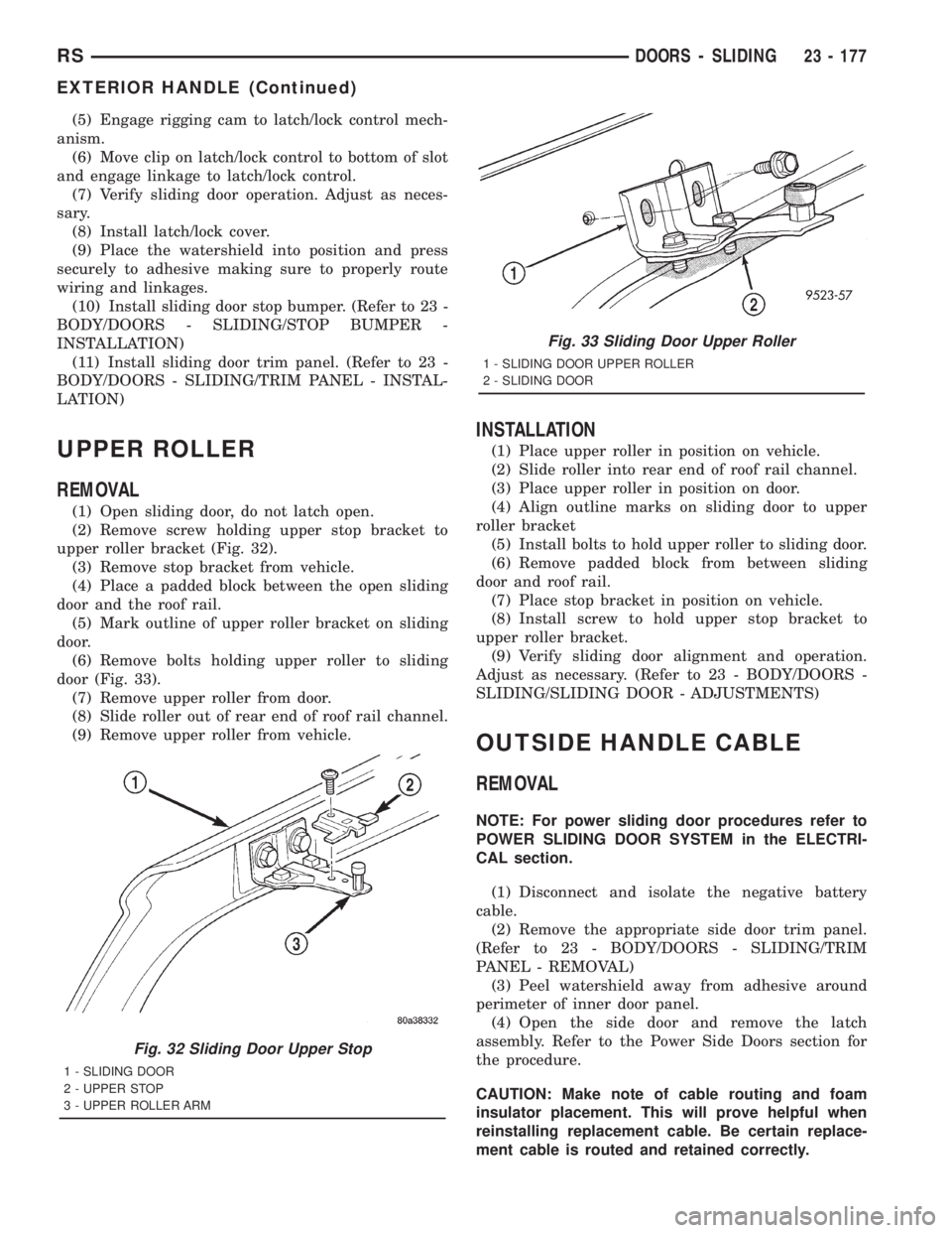
(1) Open sliding door, do not latch open.
(2) Remove screw holding upper stop bracket to
upper roller bracket (Fig. 32).
(3) Remove stop bracket from vehicle.
(4) Place a padded block between the open sliding
door and the roof rail.
(5) Mark outline of upper roller bracket on sliding
door.
(6) Remove bolts holding upper roller to sliding
door (Fig. 33).
(7) Remove upper roller from door.
(8) Slide roller out of rear end of roof rail channel.
(9) Remove upper roller from vehicle.
INSTALLATION
(1) Place upper roller in position on vehicle.
(2) Slide roller into rear end of roof rail channel.
(3) Place upper roller in position on door.
(4) Align outline marks on sliding door to upper
roller bracket
(5) Install bolts to hold upper roller to sliding door.
(6) Remove padded block from between sliding
door and roof rail.
(7) Place stop bracket in position on vehicle.
(8) Install screw to hold upper stop bracket to
upper roller bracket.
(9) Verify sliding door alignment and operation.
Adjust as necessary. (Refer to 23 - BODY/DOORS -
SLIDING/SLIDING DOOR - ADJUSTMENTS)
OUTSIDE HANDLE CABLE
REMOVAL
NOTE: For power sliding door procedures refer to
POWER SLIDING DOOR SYSTEM in the ELECTRI-
CAL section.
(1) Disconnect and isolate the negative battery
cable.
(2) Remove the appropriate side door trim panel.
(Refer to 23 - BODY/DOORS - SLIDING/TRIM
PANEL - REMOVAL)
(3) Peel watershield away from adhesive around
perimeter of inner door panel.
(4) Open the side door and remove the latch
assembly. Refer to the Power Side Doors section for
the procedure.
CAUTION: Make note of cable routing and foam
insulator placement. This will prove helpful when
reinstalling replacement cable. Be certain replace-
ment cable is routed and retained correctly.
Fig. 32 Sliding Door Upper Stop
1 - SLIDING DOOR
2 - UPPER STOP
3 - UPPER ROLLER ARM
Fig. 33 Sliding Door Upper Roller
1 - SLIDING DOOR UPPER ROLLER
2 - SLIDING DOOR
RSDOORS - SLIDING23 - 177
EXTERIOR HANDLE (Continued)