2001 CHRYSLER VOYAGER roof
[x] Cancel search: roofPage 3599 of 4284
SUN VISOR SUPPORT
REMOVAL
(1) Disengage sun visor from support.
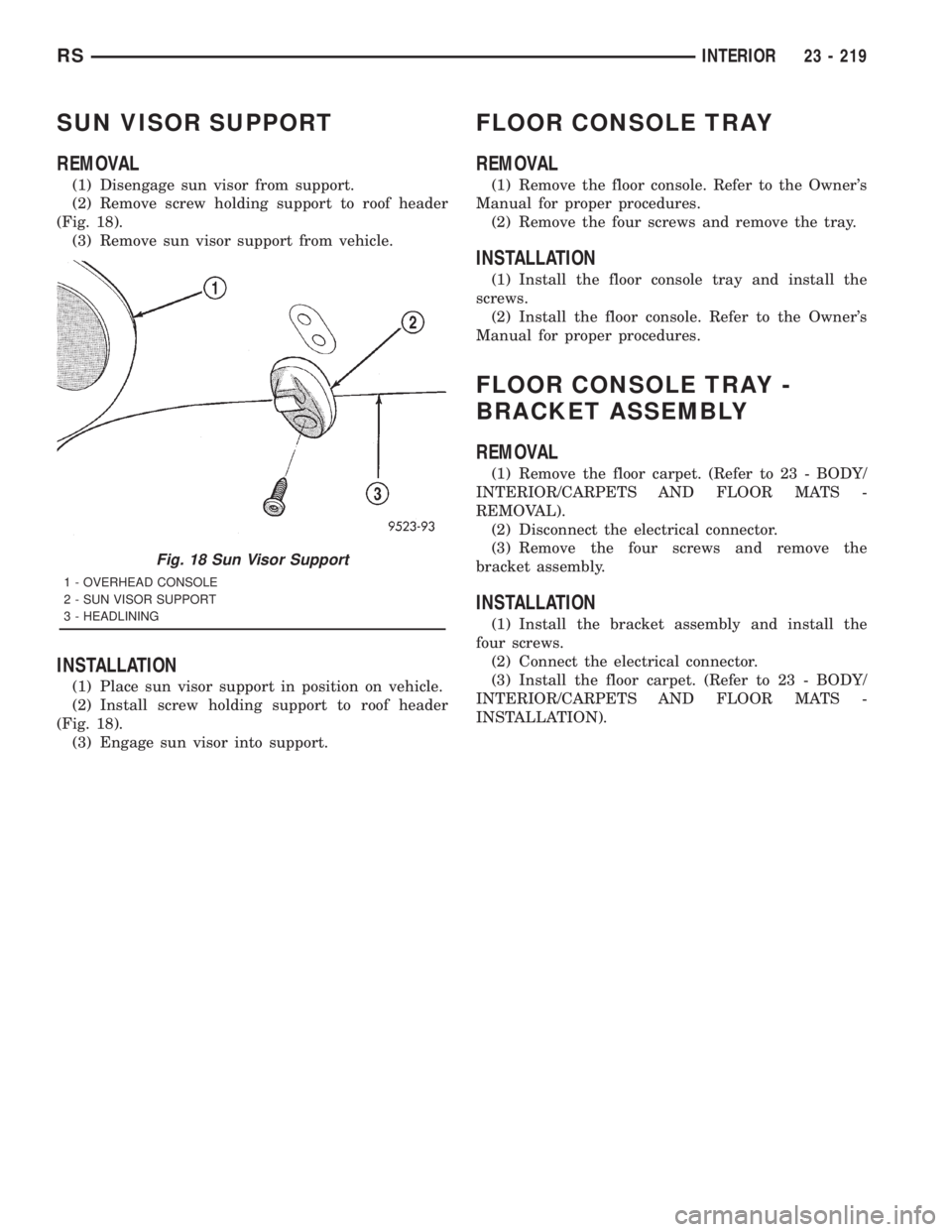
(2) Remove screw holding support to roof header
(Fig. 18).
(3) Remove sun visor support from vehicle.
INSTALLATION
(1) Place sun visor support in position on vehicle.
(2) Install screw holding support to roof header
(Fig. 18).
(3) Engage sun visor into support.
FLOOR CONSOLE TRAY
REMOVAL
(1) Remove the floor console. Refer to the Owner's
Manual for proper procedures.
(2) Remove the four screws and remove the tray.
INSTALLATION
(1) Install the floor console tray and install the
screws.
(2) Install the floor console. Refer to the Owner's
Manual for proper procedures.
FLOOR CONSOLE TRAY -
BRACKET ASSEMBLY
REMOVAL
(1) Remove the floor carpet. (Refer to 23 - BODY/
INTERIOR/CARPETS AND FLOOR MATS -
REMOVAL).
(2) Disconnect the electrical connector.
(3) Remove the four screws and remove the
bracket assembly.
INSTALLATION
(1) Install the bracket assembly and install the
four screws.
(2) Connect the electrical connector.
(3) Install the floor carpet. (Refer to 23 - BODY/
INTERIOR/CARPETS AND FLOOR MATS -
INSTALLATION).
Fig. 18 Sun Visor Support
1 - OVERHEAD CONSOLE
2 - SUN VISOR SUPPORT
3 - HEADLINING
RSINTERIOR23 - 219
Page 3623 of 4284
STATIONARY GLASS
TABLE OF CONTENTS
page page
WINDSHIELD
DESCRIPTION..........................243
WARNING.............................243
REMOVAL.............................243
INSTALLATION..........................244
SLIDING DOOR GLASS
REMOVAL.............................245INSTALLATION..........................245
QUARTER WINDOW
REMOVAL.............................246
INSTALLATION..........................246
REAR DOOR GLASS
REMOVAL.............................246
INSTALLATION..........................246
WINDSHIELD
DESCRIPTION
The windshield is attached to the window frame
with urethane adhesive. The urethane adhesive is
applied cold and seals the surface area between the
window opening and the glass. The primer adheres
the urethane adhesive to the windshield.
It is difficult to salvage a windshield during the
removal operation. The windshield is part of the
structural support for the roof. The urethane bonding
used to secure the windshield to the fence is difficult
to cut or clean from any surface. If the moldings are
set in urethane, it would also be unlikely they could
be salvaged. Before removing the windshield, check
the availability of the windshield and moldings from
the parts supplier.
WINDSHIELD SAFETY PRECAUTIONS
WARNING: DO NOT OPERATE THE VEHICLE
WITHIN 24 HOURS OF WINDSHIELD INSTALLATION.
IT TAKES AT LEAST 24 HOURS FOR URETHANE
ADHESIVE TO CURE. IF IT IS NOT CURED, THE
WINDSHIELD MAY NOT PERFORM PROPERLY IN
AN ACCIDENT.
URETHANE ADHESIVES ARE APPLIED AS A SYS-
TEM. USE GLASS CLEANER, GLASS PREP SOL-
VENT, GLASS PRIMER, PVC (VINYL) PRIMER AND
PINCH WELD (FENCE) PRIMER PROVIDED BY THE
ADHESIVE MANUFACTURER. IF NOT, STRUCTURAL
INTEGRITY COULD BE COMPROMISED.
DAIMLERCHRYSLER DOES NOT RECOMMEND
GLASS ADHESIVE BY BRAND. TECHNICIANS
SHOULD REVIEW PRODUCT LABELS AND TECHNI-
CAL DATA SHEETS, AND USE ONLY ADHESIVES
THAT THEIR MANUFACTURES WARRANT WILL
RESTORE A VEHICLE TO THE REQUIREMENTS OF
FMVSS 212. TECHNICIANS SHOULD ALSO INSURE
THAT PRIMERS AND CLEANERS ARE COMPATIBLEWITH THE PARTICULAR ADHESIVE USED.
BE SURE TO REFER TO THE URETHANE MANU-
FACTURER'S DIRECTIONS FOR CURING TIME
SPECIFICATIONS, AND DO NOT USE ADHESIVE
AFTER ITS EXPIRATION DATE.
VAPORS THAT ARE EMITTED FROM THE URE-
THANE ADHESIVE OR PRIMER COULD CAUSE
PERSONAL INJURY. USE THEM IN A WELL-VENTI-
LATED AREA.
SKIN CONTACT WITH URETHANE ADHESIVE
SHOULD BE AVOIDED. PERSONAL INJURY MAY
RESULT.
ALWAYS WEAR EYE AND HAND PROTECTION
WHEN WORKING WITH GLASS.
CAUTION: Protect all painted and trimmed surfaces
from coming in contact with urethane or primers.
Be careful not to damage painted surfaces when
removing moldings or cutting urethane around
windshield.
REMOVAL
WINDSHIELD REMOVAL ± EXTERIOR METHOD
The urethane adhesive holding the windshield to
the opening pinch weld (fence) can be cut using a
sharp cold knife from the exterior of the vehicle.
Using the cold knife method is effective if the wind-
shield is already broken. If the glass must be sal-
vaged, cutting the urethane adhesive from the
interior of the vehicle using a reciprocating or oscil-
lating power knife is recommended.
(1) Remove inside rear view mirror.
(2) Remove windshield wiper arms.
(3) Remove cowl cover.
(4) Remove A-pillar trim panels.
(5) Disconnect wire connectors to windshield
defroster grid.
RSSTATIONARY GLASS23 - 243
Page 3624 of 4284
(6) Place protective covers over instrument panel
and hood.
(7) Remove windshield molding. Using pliers, pull
outward on molding at the bottom of A-pillars.
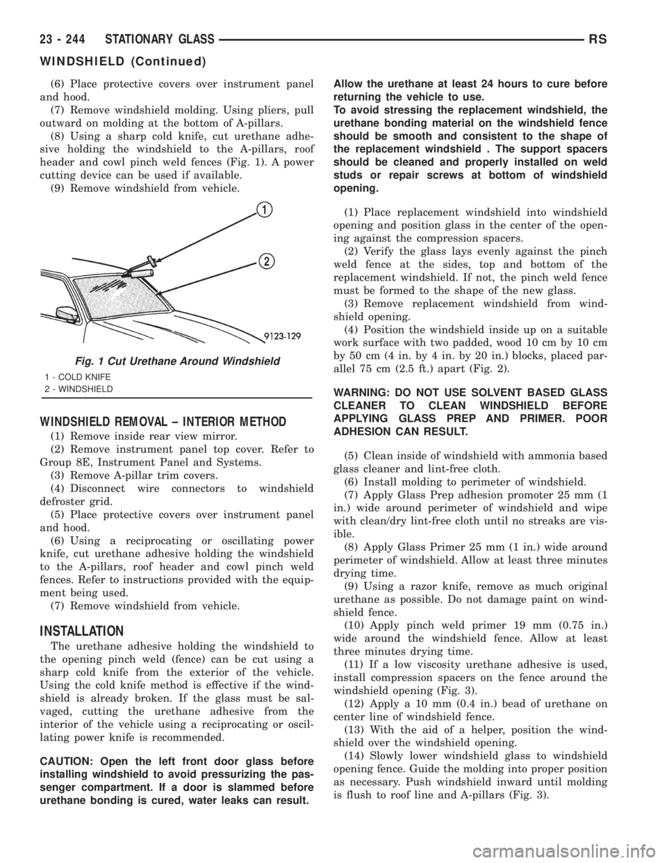
(8) Using a sharp cold knife, cut urethane adhe-
sive holding the windshield to the A-pillars, roof
header and cowl pinch weld fences (Fig. 1). A power
cutting device can be used if available.
(9) Remove windshield from vehicle.
WINDSHIELD REMOVAL ± INTERIOR METHOD
(1) Remove inside rear view mirror.
(2) Remove instrument panel top cover. Refer to
Group 8E, Instrument Panel and Systems.
(3) Remove A-pillar trim covers.
(4) Disconnect wire connectors to windshield
defroster grid.
(5) Place protective covers over instrument panel
and hood.
(6) Using a reciprocating or oscillating power
knife, cut urethane adhesive holding the windshield
to the A-pillars, roof header and cowl pinch weld
fences. Refer to instructions provided with the equip-
ment being used.
(7) Remove windshield from vehicle.
INSTALLATION
The urethane adhesive holding the windshield to
the opening pinch weld (fence) can be cut using a
sharp cold knife from the exterior of the vehicle.
Using the cold knife method is effective if the wind-
shield is already broken. If the glass must be sal-
vaged, cutting the urethane adhesive from the
interior of the vehicle using a reciprocating or oscil-
lating power knife is recommended.
CAUTION: Open the left front door glass before
installing windshield to avoid pressurizing the pas-
senger compartment. If a door is slammed before
urethane bonding is cured, water leaks can result.Allow the urethane at least 24 hours to cure before
returning the vehicle to use.
To avoid stressing the replacement windshield, the
urethane bonding material on the windshield fence
should be smooth and consistent to the shape of
the replacement windshield . The support spacers
should be cleaned and properly installed on weld
studs or repair screws at bottom of windshield
opening.
(1) Place replacement windshield into windshield
opening and position glass in the center of the open-
ing against the compression spacers.
(2) Verify the glass lays evenly against the pinch
weld fence at the sides, top and bottom of the
replacement windshield. If not, the pinch weld fence
must be formed to the shape of the new glass.
(3) Remove replacement windshield from wind-
shield opening.
(4) Position the windshield inside up on a suitable
work surface with two padded, wood 10 cm by 10 cm
by 50 cm (4 in. by 4 in. by 20 in.) blocks, placed par-
allel 75 cm (2.5 ft.) apart (Fig. 2).
WARNING: DO NOT USE SOLVENT BASED GLASS
CLEANER TO CLEAN WINDSHIELD BEFORE
APPLYING GLASS PREP AND PRIMER. POOR
ADHESION CAN RESULT.
(5) Clean inside of windshield with ammonia based
glass cleaner and lint-free cloth.
(6) Install molding to perimeter of windshield.
(7) Apply Glass Prep adhesion promoter 25 mm (1
in.) wide around perimeter of windshield and wipe
with clean/dry lint-free cloth until no streaks are vis-
ible.
(8) Apply Glass Primer 25 mm (1 in.) wide around
perimeter of windshield. Allow at least three minutes
drying time.
(9) Using a razor knife, remove as much original
urethane as possible. Do not damage paint on wind-
shield fence.
(10) Apply pinch weld primer 19 mm (0.75 in.)
wide around the windshield fence. Allow at least
three minutes drying time.
(11) If a low viscosity urethane adhesive is used,
install compression spacers on the fence around the
windshield opening (Fig. 3).
(12) Apply a 10 mm (0.4 in.) bead of urethane on
center line of windshield fence.
(13) With the aid of a helper, position the wind-
shield over the windshield opening.
(14) Slowly lower windshield glass to windshield
opening fence. Guide the molding into proper position
as necessary. Push windshield inward until molding
is flush to roof line and A-pillars (Fig. 3).
Fig. 1 Cut Urethane Around Windshield
1 - COLD KNIFE
2 - WINDSHIELD
23 - 244 STATIONARY GLASSRS
WINDSHIELD (Continued)
Page 3684 of 4284
DISTRIBUTION - REAR
TABLE OF CONTENTS
page page
AIR OUTLETS
DESCRIPTION...........................54
REMOVAL..............................54
INSTALLATION...........................54
A/C DISTRIBUTION DUCT
REMOVAL..............................55
INSTALLATION...........................55
BLOWER MOTOR
DESCRIPTION...........................55
OPERATION.............................55DIAGNOSIS AND TESTING.................56
BLOWER MOTOR......................56
REMOVAL..............................58
INSTALLATION...........................58
REAR HEATER-A/C HOUSING
REMOVAL..............................58
INSTALLATION...........................60
REAR HEATER DISTRIBUTION DUCT
REMOVAL..............................61
INSTALLATION...........................61
AIR OUTLETS
DESCRIPTION
Based upon the system mode selected, conditioned
air can exit the rear heater-A/C unit housing through
one or a combination of the two main housing out-
lets: air conditioner, or heater. Once the conditioned
air exits the unit housing, it is directed through
molded plastic ducts to the various outlets in the
vehicle interior. These outlets and their locations are
as follows:
²Floor Outlets- Three floor outlets with fixed
vanes are located in the right quarter trim panel,
near the floor. These outlets distribute air from the
rear heater distribution duct to the intermediate and
rear seat occupants. The floor outlets are integral to
the right quarter trim panel and, if faulty or dam-
aged, the quarter trim panel must be replaced.
²Overhead Outlets- Four (two right side and
two left side) fully adjustable outlets along the roof
rails distribute air from the rear A/C distribution
duct and the headliner ducts to the intermediate and
rear seat occupants. The headliner ducts are integral
to the headliner panel. Each overhead outlet is
housed in a headliner bezel. The two forward head-
liner bezels also feature a courtesy lamp, a fold-away
coat hook, and a fold-away assist handle. The over-
head outlets can be removed from the headliner
bezels individually for service replacement.
REMOVAL
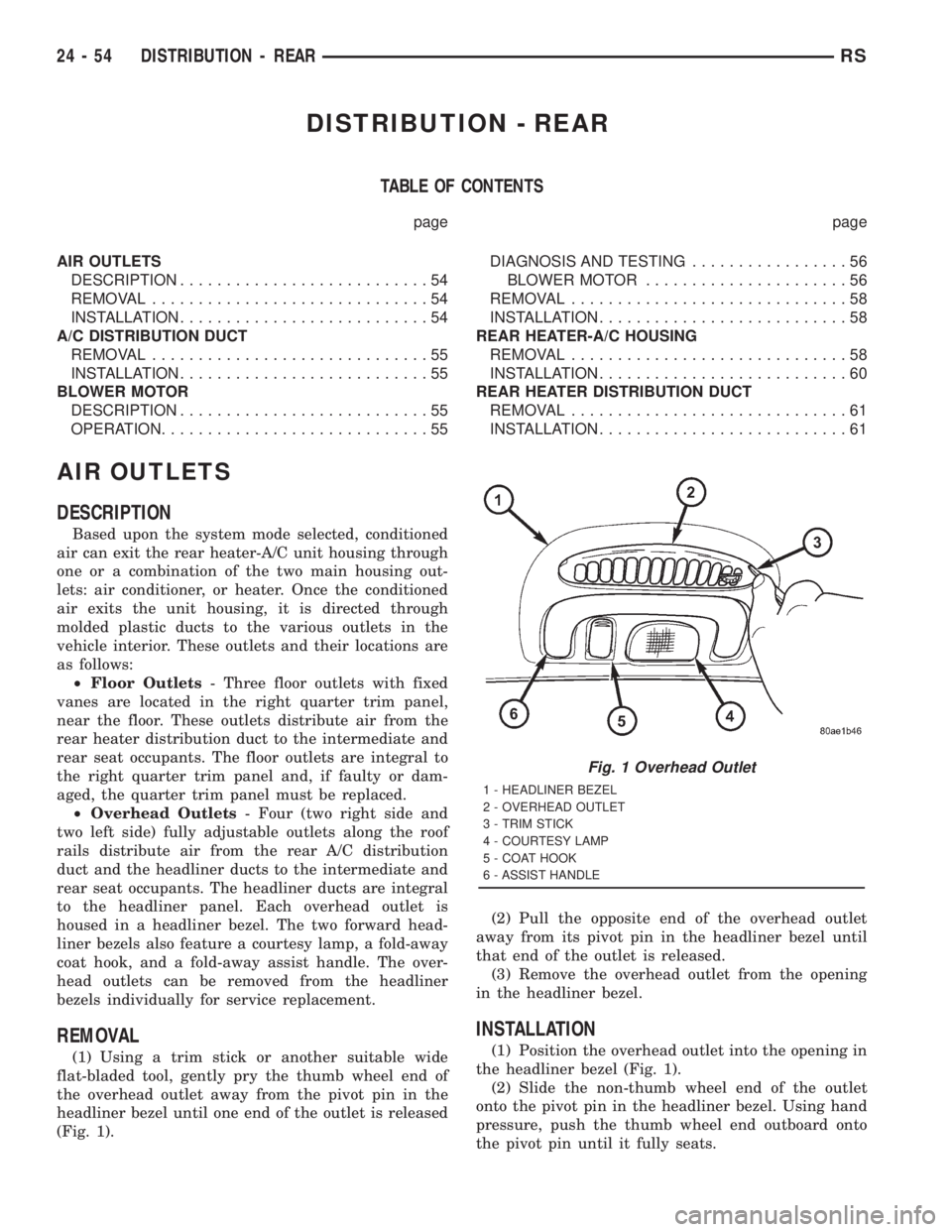
(1) Using a trim stick or another suitable wide
flat-bladed tool, gently pry the thumb wheel end of
the overhead outlet away from the pivot pin in the
headliner bezel until one end of the outlet is released
(Fig. 1).(2) Pull the opposite end of the overhead outlet
away from its pivot pin in the headliner bezel until
that end of the outlet is released.
(3) Remove the overhead outlet from the opening
in the headliner bezel.
INSTALLATION
(1) Position the overhead outlet into the opening in
the headliner bezel (Fig. 1).
(2) Slide the non-thumb wheel end of the outlet
onto the pivot pin in the headliner bezel. Using hand
pressure, push the thumb wheel end outboard onto
the pivot pin until it fully seats.
Fig. 1 Overhead Outlet
1 - HEADLINER BEZEL
2 - OVERHEAD OUTLET
3 - TRIM STICK
4 - COURTESY LAMP
5 - COAT HOOK
6 - ASSIST HANDLE
24 - 54 DISTRIBUTION - REARRS
Page 3689 of 4284
(2) Drain the engine cooling system. (Refer to 7 -
COOLING - STANDARD PROCEDURE - COOLING
SYSTEM DRAIN).
(3) Disconnect and isolate the battery negative
cable.
(4) Raise and support the vehicle.
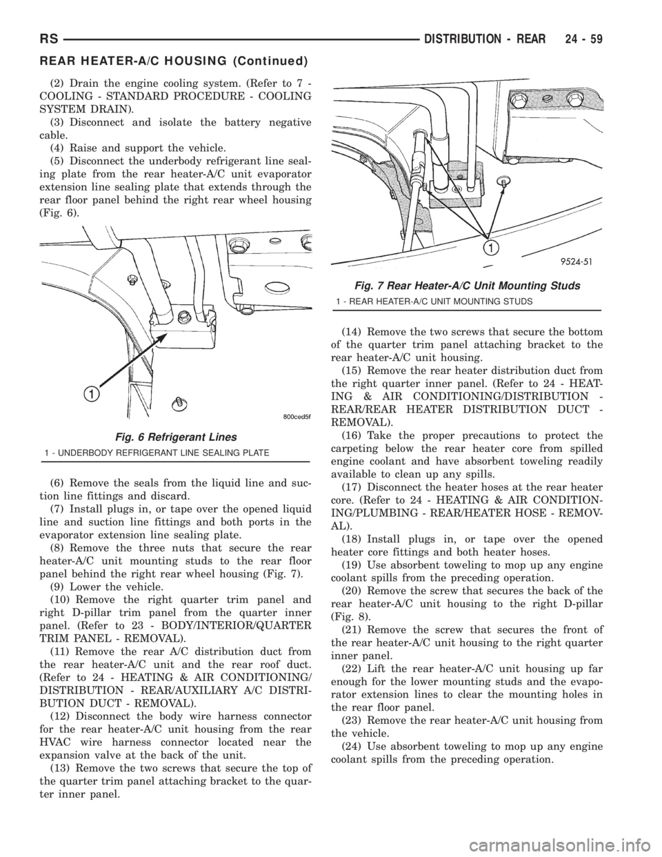
(5) Disconnect the underbody refrigerant line seal-
ing plate from the rear heater-A/C unit evaporator
extension line sealing plate that extends through the
rear floor panel behind the right rear wheel housing
(Fig. 6).
(6) Remove the seals from the liquid line and suc-
tion line fittings and discard.
(7) Install plugs in, or tape over the opened liquid
line and suction line fittings and both ports in the
evaporator extension line sealing plate.
(8) Remove the three nuts that secure the rear
heater-A/C unit mounting studs to the rear floor
panel behind the right rear wheel housing (Fig. 7).
(9) Lower the vehicle.
(10) Remove the right quarter trim panel and
right D-pillar trim panel from the quarter inner
panel. (Refer to 23 - BODY/INTERIOR/QUARTER
TRIM PANEL - REMOVAL).
(11) Remove the rear A/C distribution duct from
the rear heater-A/C unit and the rear roof duct.
(Refer to 24 - HEATING & AIR CONDITIONING/
DISTRIBUTION - REAR/AUXILIARY A/C DISTRI-
BUTION DUCT - REMOVAL).
(12) Disconnect the body wire harness connector
for the rear heater-A/C unit housing from the rear
HVAC wire harness connector located near the
expansion valve at the back of the unit.
(13) Remove the two screws that secure the top of
the quarter trim panel attaching bracket to the quar-
ter inner panel.(14) Remove the two screws that secure the bottom
of the quarter trim panel attaching bracket to the
rear heater-A/C unit housing.
(15) Remove the rear heater distribution duct from
the right quarter inner panel. (Refer to 24 - HEAT-
ING & AIR CONDITIONING/DISTRIBUTION -
REAR/REAR HEATER DISTRIBUTION DUCT -
REMOVAL).
(16) Take the proper precautions to protect the
carpeting below the rear heater core from spilled
engine coolant and have absorbent toweling readily
available to clean up any spills.
(17) Disconnect the heater hoses at the rear heater
core. (Refer to 24 - HEATING & AIR CONDITION-
ING/PLUMBING - REAR/HEATER HOSE - REMOV-
AL).
(18) Install plugs in, or tape over the opened
heater core fittings and both heater hoses.
(19) Use absorbent toweling to mop up any engine
coolant spills from the preceding operation.
(20) Remove the screw that secures the back of the
rear heater-A/C unit housing to the right D-pillar
(Fig. 8).
(21) Remove the screw that secures the front of
the rear heater-A/C unit housing to the right quarter
inner panel.
(22) Lift the rear heater-A/C unit housing up far
enough for the lower mounting studs and the evapo-
rator extension lines to clear the mounting holes in
the rear floor panel.
(23) Remove the rear heater-A/C unit housing from
the vehicle.
(24) Use absorbent toweling to mop up any engine
coolant spills from the preceding operation.
Fig. 6 Refrigerant Lines
1 - UNDERBODY REFRIGERANT LINE SEALING PLATE
Fig. 7 Rear Heater-A/C Unit Mounting Studs
1 - REAR HEATER-A/C UNIT MOUNTING STUDS
RSDISTRIBUTION - REAR24-59
REAR HEATER-A/C HOUSING (Continued)
Page 3691 of 4284
(8) Install and tighten the two screws that secure
the bottom of the quarter trim panel attaching
bracket to the rear heater-A/C unit housing. Tighten
the screws to 1.7 N´m (15 in. lbs.).
(9) Install and tighten the two screws that secure
the top of the quarter trim panel attaching bracket to
the quarter inner panel.
(10) Reconnect the body wire harness connector for
the rear heater-A/C unit housing to the rear HVAC
wire harness connector located near the expansion
valve at the back of the unit.
(11) Reinstall the auxiliary A/C distribution duct
onto the rear heater-A/C unit and the rear roof duct.
(Refer to 24 - HEATING & AIR CONDITIONING/
DISTRIBUTION - REAR/AUXILIARY A/C DISTRI-
BUTION DUCT - INSTALLATION).
(12) Reinstall the right quarter trim panel and
right D-pillar trim panel onto the quarter inner
panel. (Refer to 23 - BODY/INTERIOR/QUARTER
TRIM PANEL - INSTALLATION).
(13) Raise and support the vehicle.
(14) Install and tighten the three nuts that secure
the rear heater-A/C unit mounting studs to the rear
floor panel behind the right rear wheel housing (Fig.
7). Tighten the nuts to 9 N´m (80 in. lbs.).
(15) Remove the tape or plugs from the underbody
liquid line and suction line fittings and both ports in
the rear heater-A/C unit evaporator extension line
sealing plate that extends through the rear floor
panel behind the right rear wheel housing.
(16) Lubricate new rubber O-ring seals with clean
refrigerant oil and install them on the liquid line and
suction line fittings.
(17) Reconnect the underbody refrigerant line seal-
ing plate to the evaporator extension line sealing
plate (Fig. 6).
(18) Install and tighten the screw that secures the
underbody refrigerant line sealing plate to the evap-
orator extension line sealing plate. Tighten the screw
to 23 N´m (17 ft. lbs.).
(19) Lower the vehicle.
(20) Reconnect the battery negative cable.
(21) Refill the engine cooling system. (Refer to 7 -
COOLING - STANDARD PROCEDURE - COOLING
SYSTEM REFILL).
(22) Evacuate the refrigerant system. (Refer to 24
- HEATING & AIR CONDITIONING/PLUMBING -
FRONT/REFRIGERANT - STANDARD PROCE-
DURE - REFRIGERANT SYSTEM EVACUATE).
(23) Charge the refrigerant system. (Refer to 24 -
HEATING & AIR CONDITIONING/PLUMBING -
FRONT/REFRIGERANT - STANDARD PROCE-
DURE - REFRIGERANT SYSTEM CHARGE).REAR HEATER DISTRIBUTION
DUCT
REMOVAL
(1) Remove the trim from the right quarter inner
panel. (Refer to 23 - BODY/INTERIOR/RIGHT
QUARTER TRIM PANEL - REMOVAL).
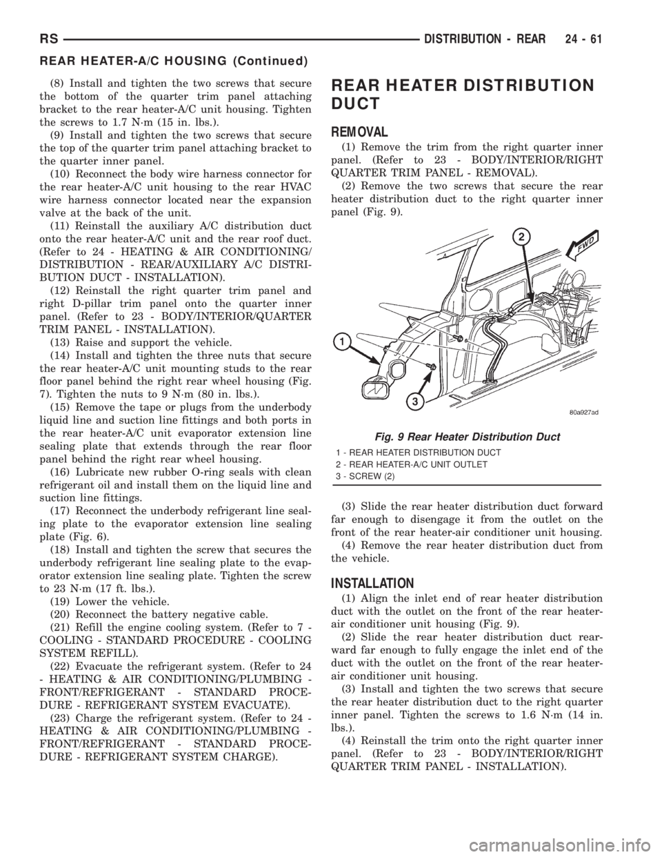
(2) Remove the two screws that secure the rear
heater distribution duct to the right quarter inner
panel (Fig. 9).
(3) Slide the rear heater distribution duct forward
far enough to disengage it from the outlet on the
front of the rear heater-air conditioner unit housing.
(4) Remove the rear heater distribution duct from
the vehicle.
INSTALLATION
(1) Align the inlet end of rear heater distribution
duct with the outlet on the front of the rear heater-
air conditioner unit housing (Fig. 9).
(2) Slide the rear heater distribution duct rear-
ward far enough to fully engage the inlet end of the
duct with the outlet on the front of the rear heater-
air conditioner unit housing.
(3) Install and tighten the two screws that secure
the rear heater distribution duct to the right quarter
inner panel. Tighten the screws to 1.6 N´m (14 in.
lbs.).
(4) Reinstall the trim onto the right quarter inner
panel. (Refer to 23 - BODY/INTERIOR/RIGHT
QUARTER TRIM PANEL - INSTALLATION).
Fig. 9 Rear Heater Distribution Duct
1 - REAR HEATER DISTRIBUTION DUCT
2 - REAR HEATER-A/C UNIT OUTLET
3 - SCREW (2)
RSDISTRIBUTION - REAR24-61
REAR HEATER-A/C HOUSING (Continued)