2001 CHRYSLER VOYAGER fuel tank removal
[x] Cancel search: fuel tank removalPage 2884 of 4284
(9) Fill fuel tank, replace cap, and connect battery
negative cable.
(10) Use the DRBIIItscan tool to pressurize the
fuel system. Check for leaks.
FUEL TANK FILLER TUBE
REMOVAL
(1) Disconnect the negative battery cable.
(2) Remove the 3 screws at the filler door.
(3) Raise and support vehicle
(4) Remove the left rear tire.
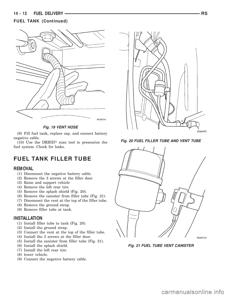
(5) Remove the splash shield (Fig. 20).
(6) Remove the canister from filler tube (Fig. 21).
(7) Disconnect the vent at the top of the filler tube.
(8) Remove the ground strap.
(9) Remove filler tube at tank.
INSTALLATION
(1) Install filler tube to tank (Fig. 20).
(2) Install the ground strap.
(3) Connect the vent at the top of the filler tube.
(4) Install the 3 screws at the filler door.
(5) Install the canister from filler tube (Fig. 21).
(6) Install the splash shield.
(7) Install the left rear tire.
(8) lower vehicle.
(9) Connect the negative battery cable.
Fig. 19 VENT HOSE
Fig. 20 FUEL FILLER TUBE AND VENT TUBE
Fig. 21 FUEL TUBE VENT CANISTER
14 - 12 FUEL DELIVERYRS
FUEL TANK (Continued)
Page 2885 of 4284
INLET FILTER
REMOVAL
(1) Remove fuel pump module. Refer to Fuel Pump
Module Removal in this section.
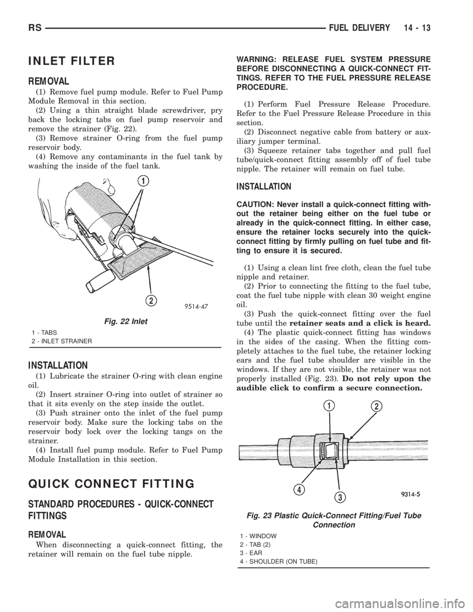
(2) Using a thin straight blade screwdriver, pry
back the locking tabs on fuel pump reservoir and
remove the strainer (Fig. 22).
(3) Remove strainer O-ring from the fuel pump
reservoir body.
(4) Remove any contaminants in the fuel tank by
washing the inside of the fuel tank.
INSTALLATION
(1) Lubricate the strainer O-ring with clean engine
oil.
(2) Insert strainer O-ring into outlet of strainer so
that it sits evenly on the step inside the outlet.
(3) Push strainer onto the inlet of the fuel pump
reservoir body. Make sure the locking tabs on the
reservoir body lock over the locking tangs on the
strainer.
(4) Install fuel pump module. Refer to Fuel Pump
Module Installation in this section.
QUICK CONNECT FITTING
STANDARD PROCEDURES - QUICK-CONNECT
FITTINGS
REMOVAL
When disconnecting a quick-connect fitting, the
retainer will remain on the fuel tube nipple.WARNING: RELEASE FUEL SYSTEM PRESSURE
BEFORE DISCONNECTING A QUICK-CONNECT FIT-
TINGS. REFER TO THE FUEL PRESSURE RELEASE
PROCEDURE.
(1) Perform Fuel Pressure Release Procedure.
Refer to the Fuel Pressure Release Procedure in this
section.
(2) Disconnect negative cable from battery or aux-
iliary jumper terminal.
(3) Squeeze retainer tabs together and pull fuel
tube/quick-connect fitting assembly off of fuel tube
nipple. The retainer will remain on fuel tube.
INSTALLATION
CAUTION: Never install a quick-connect fitting with-
out the retainer being either on the fuel tube or
already in the quick-connect fitting. In either case,
ensure the retainer locks securely into the quick-
connect fitting by firmly pulling on fuel tube and fit-
ting to ensure it is secured.
(1) Using a clean lint free cloth, clean the fuel tube
nipple and retainer.
(2) Prior to connecting the fitting to the fuel tube,
coat the fuel tube nipple with clean 30 weight engine
oil.
(3) Push the quick-connect fitting over the fuel
tube until theretainer seats and a click is heard.
(4) The plastic quick-connect fitting has windows
in the sides of the casing. When the fitting com-
pletely attaches to the fuel tube, the retainer locking
ears and the fuel tube shoulder are visible in the
windows. If they are not visible, the retainer was not
properly installed (Fig. 23).Do not rely upon the
audible click to confirm a secure connection.
Fig. 22 Inlet
1 - TABS
2 - INLET STRAINER
Fig. 23 Plastic Quick-Connect Fitting/Fuel Tube
Connection
1 - WINDOW
2-TAB(2)
3 - EAR
4 - SHOULDER (ON TUBE)
RSFUEL DELIVERY14-13
Page 2887 of 4284
PLASTIC RETAINER RING TYPE FITTING
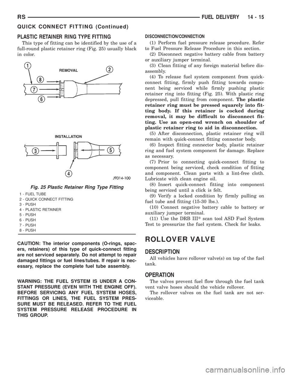
This type of fitting can be identified by the use of a
full-round plastic retainer ring (Fig. 25) usually black
in color.
CAUTION: The interior components (O-rings, spac-
ers, retainers) of this type of quick-connect fitting
are not serviced separately. Do not attempt to repair
damaged fittings or fuel lines/tubes. If repair is nec-
essary, replace the complete fuel tube assembly.
WARNING: THE FUEL SYSTEM IS UNDER A CON-
STANT PRESSURE (EVEN WITH THE ENGINE OFF).
BEFORE SERVICING ANY FUEL SYSTEM HOSES,
FITTINGS OR LINES, THE FUEL SYSTEM PRES-
SURE MUST BE RELEASED. REFER TO THE FUEL
SYSTEM PRESSURE RELEASE PROCEDURE IN
THIS GROUP.DISCONNECTION/CONNECTION
(1) Perform fuel pressure release procedure. Refer
to Fuel Pressure Release Procedure in this section.
(2) Disconnect negative battery cable from battery
or auxiliary jumper terminal.
(3) Clean fitting of any foreign material before dis-
assembly.
(4) To release fuel system component from quick-
connect fitting, firmly push fitting towards compo-
nent being serviced while firmly pushing plastic
retainer ring into fitting (Fig. 25). With plastic ring
depressed, pull fitting from component.The plastic
retainer ring must be pressed squarely into fit-
ting body. If this retainer is cocked during
removal, it may be difficult to disconnect fit-
ting. Use an open-end wrench on shoulder of
plastic retainer ring to aid in disconnection.
(5) After disconnection, plastic retainer ring will
remain with quick-connect fitting connector body.
(6) Inspect fitting connector body, plastic retainer
ring and fuel system component for damage. Replace
as necessary.
(7) Prior to connecting quick-connect fitting to
component being serviced, check condition of fitting
and component. Clean parts with a lint-free cloth.
Lubricate with clean engine oil.
(8) Insert quick-connect fitting into component
being serviced until a click is felt.
(9) Verify a locked condition by firmly pulling on
fuel tube and fitting (15-30 lbs.).
(10) Connect negative battery cable to battery or
auxiliary jumper terminal.
(11) Use the DRB IIItscan tool ASD Fuel System
Test to pressurize the fuel system. Check for leaks.
ROLLOVER VALVE
DESCRIPTION
All vehicles have rollover valve(s) on top of the fuel
tank.
OPERATION
The valves prevent fuel flow through the fuel tank
vent valve hoses should the vehicle rollover.
The rollover valves on the fuel tank are not ser-
viceable.
Fig. 25 Plastic Retainer Ring Type Fitting
1 - FUEL TUBE
2 - QUICK CONNECT FITTING
3 - PUSH
4 - PLASTIC RETAINER
5 - PUSH
6 - PUSH
7 - PUSH
8 - PUSH
RSFUEL DELIVERY14-15
QUICK CONNECT FITTING (Continued)
Page 2913 of 4284
Refer to the maintenance schedules for the recom-
mended fuel filter replacement intervals.
For draining of water from canister, refer to Fuel
Filter/Water Separator Removal/Installation section.
A Water-In-Fuel (WIF) sensor is part of the fuel fil-
ter cap. Refer to Water-In-Fuel Sensor Description/
Operation.
The fuel heater is installed into the filter/separator
housing above the fuel filter. Refer to Fuel Heater
Description/Operation.
FUEL LINES
DESCRIPTION
All fuel lines up to the fuel injection pump are con-
sidered low-pressure. This includes the fuel lines
from: the fuel tank to the fuel transfer pump, and
the fuel transfer pump to the fuel injection pump.
The fuel return lines and the fuel drain lines are also
considered low-pressure lines. High-pressure lines
are used between the fuel injection pump and the
fuel injectors. Also refer to High-Pressure Fuel Lines
Description/Operation.
DESCRIPTIONÐHIGH PRESSURE FUEL LINES
The high-pressure fuel lines are the 4 lines located
between the fuel injection pump and the fuel injec-
torsctor tubes. All other fuel lines are considered low-
pressure lines.
OPERATIONÐHIGH PRESSURE FUEL LINES
CAUTION: The high-pressure fuel lines cannot con-
tact each other or other components. Do not
attempt to weld high-pressure fuel lines or to repair
lines that are damaged. If lines are ever kinked or
bent, they must be replaced. Use only the recom-
mended lines when replacement of high-pressure
fuel line is necessary.
High-pressure fuel lines deliver fuel under
extremely high pressure from the injection pump to
the fuel injectors. The lines expand and contract from
the high-pressure fuel pulses generated during the
injection process. All high-pressure fuel lines are of
the same length and inside diameter. Correct high-
pressure fuel line usage and installation is critical to
smooth engine operation.
WARNING: USE EXTREME CAUTION WHEN
INSPECTING FOR HIGH-PRESSURE FUEL LEAKS.
INSPECT FOR HIGH-PRESSURE FUEL LEAKS WITH
A SHEET OF CARDBOARD. HIGH FUEL INJECTION
PRESSURE CAN CAUSE PERSONAL INJURY IF
CONTACT IS MADE WITH THE SKIN.
DIAGNOSIS AND TESTING - HIGH-PRESSURE
FUEL LINE LEAKS
High-pressure fuel line leaks can cause starting
problems and poor engine performance.
WARNING: DUE TO EXTREME FUEL PRESSURES,
USE EXTREME CAUTION WHEN INSPECTING FOR
HIGH-PRESSURE FUEL LEAKS. DO NOT GET YOUR
HAND NEAR A SUSPECTED LEAK. INSPECT FOR
HIGH-PRESSURE FUEL LEAKS WITH A SHEET OF
CARDBOARD. HIGH FUEL INJECTION PRESSURE
CAN CAUSE PERSONAL INJURY IF CONTACT IS
MADE WITH THE SKIN.
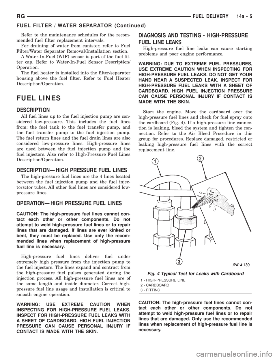
Start the engine. Move the cardboard over the
high-pressure fuel lines and check for fuel spray onto
the cardboard (Fig. 4). If a high-pressure line connec-
tion is leaking, bleed the system and tighten the con-
nection. Refer to the Air Bleed Procedure in this
group for procedures. Replace damaged, restricted or
leaking high-pressure fuel lines with the correct
replacement line.
CAUTION: The high-pressure fuel lines cannot con-
tact each other or other components. Do not
attempt to weld high-pressure fuel lines or to repair
lines that are damaged. Only use the recommended
lines when replacement of high-pressure fuel line is
necessary.
Fig. 4 Typical Test for Leaks with Cardboard
1 - HIGH-PRESSURE LINE
2 - CARDBOARD
3 - FITTING
RGFUEL DELIVERY14a-5
FUEL FILTER / WATER SEPARATOR (Continued)
Page 2914 of 4284
FUEL TRANSFER PUMP
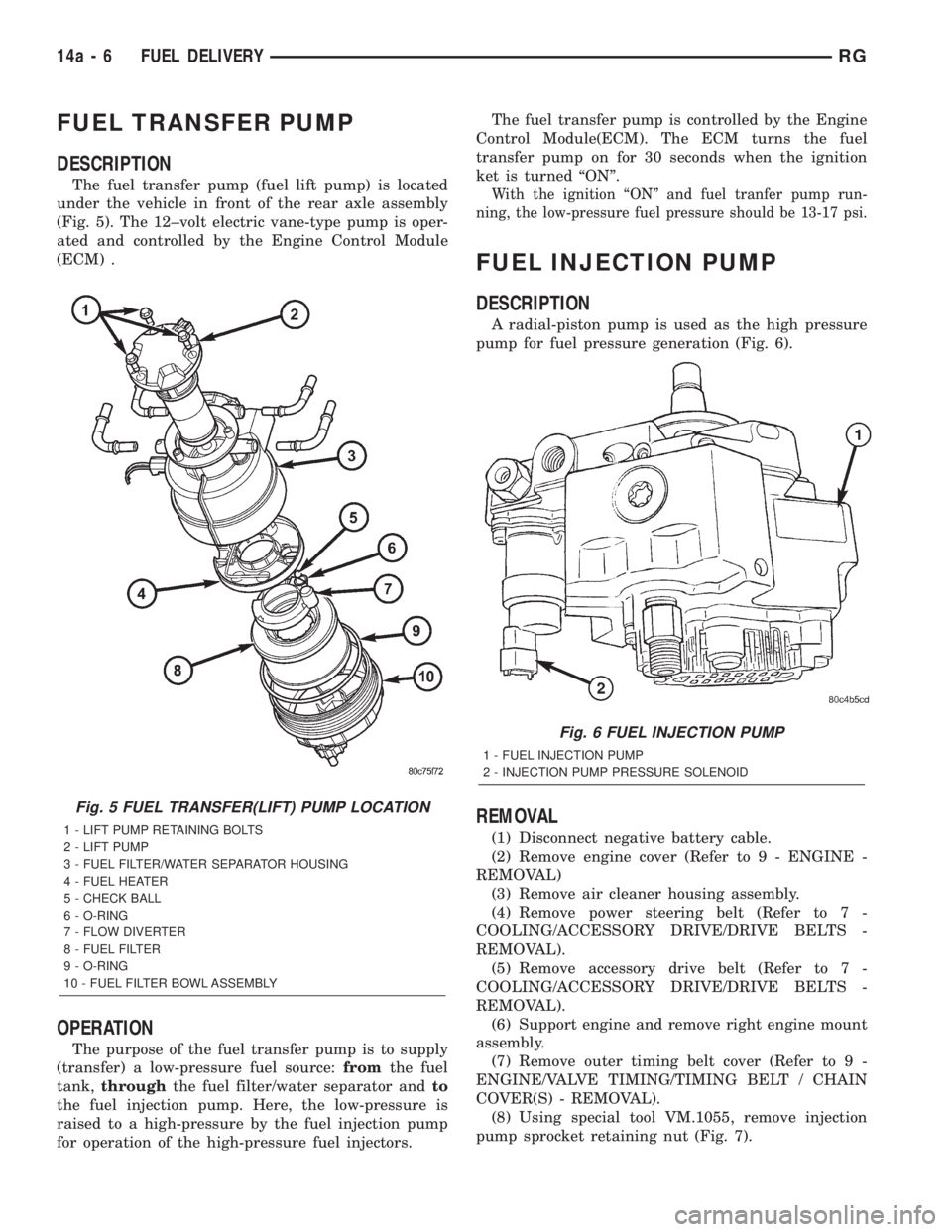
DESCRIPTION
The fuel transfer pump (fuel lift pump) is located
under the vehicle in front of the rear axle assembly
(Fig. 5). The 12±volt electric vane-type pump is oper-
ated and controlled by the Engine Control Module
(ECM) .
OPERATION
The purpose of the fuel transfer pump is to supply
(transfer) a low-pressure fuel source:fromthe fuel
tank,throughthe fuel filter/water separator andto
the fuel injection pump. Here, the low-pressure is
raised to a high-pressure by the fuel injection pump
for operation of the high-pressure fuel injectors.The fuel transfer pump is controlled by the Engine
Control Module(ECM). The ECM turns the fuel
transfer pump on for 30 seconds when the ignition
ket is turned ªONº.
With the ignition ªONº and fuel tranfer pump run-
ning, the low-pressure fuel pressure should be 13-17 psi.
FUEL INJECTION PUMP
DESCRIPTION
A radial-piston pump is used as the high pressure
pump for fuel pressure generation (Fig. 6).
REMOVAL
(1) Disconnect negative battery cable.
(2) Remove engine cover (Refer to 9 - ENGINE -
REMOVAL)
(3) Remove air cleaner housing assembly.
(4) Remove power steering belt (Refer to 7 -
COOLING/ACCESSORY DRIVE/DRIVE BELTS -
REMOVAL).
(5) Remove accessory drive belt (Refer to 7 -
COOLING/ACCESSORY DRIVE/DRIVE BELTS -
REMOVAL).
(6) Support engine and remove right engine mount
assembly.
(7) Remove outer timing belt cover (Refer to 9 -
ENGINE/VALVE TIMING/TIMING BELT / CHAIN
COVER(S) - REMOVAL).
(8) Using special tool VM.1055, remove injection
pump sprocket retaining nut (Fig. 7).
Fig. 5 FUEL TRANSFER(LIFT) PUMP LOCATION
1 - LIFT PUMP RETAINING BOLTS
2 - LIFT PUMP
3 - FUEL FILTER/WATER SEPARATOR HOUSING
4 - FUEL HEATER
5 - CHECK BALL
6 - O-RING
7 - FLOW DIVERTER
8 - FUEL FILTER
9 - O-RING
10 - FUEL FILTER BOWL ASSEMBLY
Fig. 6 FUEL INJECTION PUMP
1 - FUEL INJECTION PUMP
2 - INJECTION PUMP PRESSURE SOLENOID
14a - 6 FUEL DELIVERYRG
Page 2919 of 4284
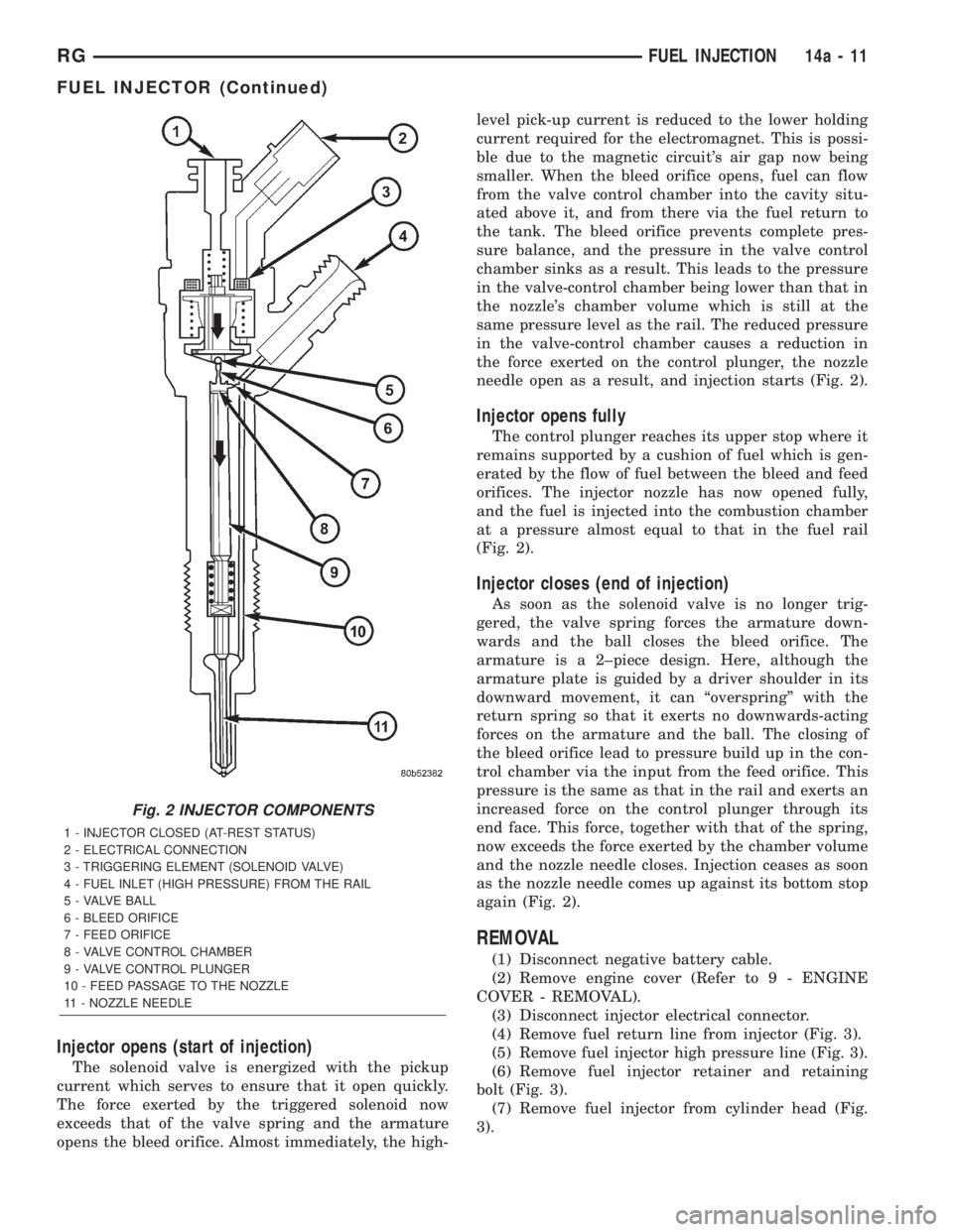
Injector opens (start of injection)
The solenoid valve is energized with the pickup
current which serves to ensure that it open quickly.
The force exerted by the triggered solenoid now
exceeds that of the valve spring and the armature
opens the bleed orifice. Almost immediately, the high-level pick-up current is reduced to the lower holding
current required for the electromagnet. This is possi-
ble due to the magnetic circuit's air gap now being
smaller. When the bleed orifice opens, fuel can flow
from the valve control chamber into the cavity situ-
ated above it, and from there via the fuel return to
the tank. The bleed orifice prevents complete pres-
sure balance, and the pressure in the valve control
chamber sinks as a result. This leads to the pressure
in the valve-control chamber being lower than that in
the nozzle's chamber volume which is still at the
same pressure level as the rail. The reduced pressure
in the valve-control chamber causes a reduction in
the force exerted on the control plunger, the nozzle
needle open as a result, and injection starts (Fig. 2).
Injector opens fully
The control plunger reaches its upper stop where it
remains supported by a cushion of fuel which is gen-
erated by the flow of fuel between the bleed and feed
orifices. The injector nozzle has now opened fully,
and the fuel is injected into the combustion chamber
at a pressure almost equal to that in the fuel rail
(Fig. 2).
Injector closes (end of injection)
As soon as the solenoid valve is no longer trig-
gered, the valve spring forces the armature down-
wards and the ball closes the bleed orifice. The
armature is a 2±piece design. Here, although the
armature plate is guided by a driver shoulder in its
downward movement, it can ªoverspringº with the
return spring so that it exerts no downwards-acting
forces on the armature and the ball. The closing of
the bleed orifice lead to pressure build up in the con-
trol chamber via the input from the feed orifice. This
pressure is the same as that in the rail and exerts an
increased force on the control plunger through its
end face. This force, together with that of the spring,
now exceeds the force exerted by the chamber volume
and the nozzle needle closes. Injection ceases as soon
as the nozzle needle comes up against its bottom stop
again (Fig. 2).
REMOVAL
(1) Disconnect negative battery cable.
(2) Remove engine cover (Refer to 9 - ENGINE
COVER - REMOVAL).
(3) Disconnect injector electrical connector.
(4) Remove fuel return line from injector (Fig. 3).
(5) Remove fuel injector high pressure line (Fig. 3).
(6) Remove fuel injector retainer and retaining
bolt (Fig. 3).
(7) Remove fuel injector from cylinder head (Fig.
3).
Fig. 2 INJECTOR COMPONENTS
1 - INJECTOR CLOSED (AT-REST STATUS)
2 - ELECTRICAL CONNECTION
3 - TRIGGERING ELEMENT (SOLENOID VALVE)
4 - FUEL INLET (HIGH PRESSURE) FROM THE RAIL
5 - VALVE BALL
6 - BLEED ORIFICE
7 - FEED ORIFICE
8 - VALVE CONTROL CHAMBER
9 - VALVE CONTROL PLUNGER
10 - FEED PASSAGE TO THE NOZZLE
11 - NOZZLE NEEDLE
RGFUEL INJECTION14a-11
FUEL INJECTOR (Continued)
Page 3591 of 4284
(2) Place B-pillar trim cover in position on vehicle.
(3) Engage hidden clips attaching trim cover to
B-pillar.
(4) Install screw attaching trim cover to B-pillar
inside bezel cavity.
(5) Install shoulder belt bezel into trim cover.
(6) Install height adjuster knob.
(7) Install shoulder belt turning loop onto height
adjuster. Tighten bolt to 39 N´m (29 ft. lbs.) torque.
(8) Place seat anchor in position on floor so web-
bing is pointed rearward and slightly outboard.
(9) Install bolt attaching lower seat belt anchor to
floor. Tighten seat belt bolt to 39 N´m (29 ft. lbs.)
torque.
CARPETS AND FLOOR MATS
REMOVAL
(1) Remove front seats. (Refer to 23 - BODY/
SEATS/SEAT - REMOVAL).
(2) Remove front center console.
(3) Remove the remaining seats. Refer to the Own-
er's Manual for the proper procedures.
(4) Remove front cowl panels and sill plates.
(5) Remove sliding door sill plates. (Refer to 23 -
BODY/INTERIOR/SLIDING DOOR SILL PLATE -
REMOVAL).
(6) Remove the cargo organizer, if equipped.
(7) Remove liftgate scuff plate. (Refer to 23 -
BODY/INTERIOR/LIFTGATE SCUFF PLATE -
REMOVAL).
(8) Remove lower B-pillar trim covers.
(9) Remove D-pillar trim covers.
(10) Remove Quarter trim panels.
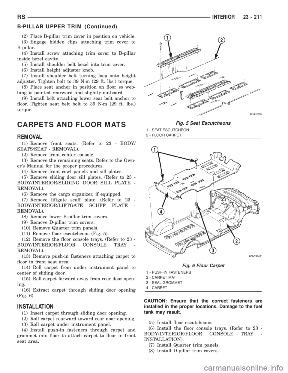
(11) Remove floor escutcheons (Fig. 5).
(12) Remove the floor console trays. (Refer to 23 -
BODY/INTERIOR/FLOOR CONSOLE TRAY -
REMOVAL).
(13) Remove push-in fasteners attaching carpet to
floor in front seat area.
(14) Roll carpet from under instrument panel to
center of sliding door.
(15) Roll carpet forward away from rear door open-
ing.
(16) Extract carpet through sliding door opening
(Fig. 6).
INSTALLATION
(1) Insert carpet through sliding door opening.
(2) Roll carpet rearward toward rear door opening.
(3) Roll carpet under instrument panel.
(4) Install push-in fasteners through carpet and
grommet into floor to attach carpet to floor in front
seat area.CAUTION: Ensure that the correct fasteners are
installed in the proper locations. Damage to the fuel
tank may result.
(5) Install floor escutcheons.
(6) Install the floor console trays. (Refer to 23 -
BODY/INTERIOR/FLOOR CONSOLE TRAY -
INSTALLATION).
(7) Install Quarter trim panels.
(8) Install D-pillar trim covers.
Fig. 5 Seat Escutcheons
1 - SEAT ESCUTCHEON
2 - FLOOR CARPET
Fig. 6 Floor Carpet
1 - PUSH-IN FASTENERS
2 - CARPET MAT
3 - SEAL GROMMET
4 - CARPET
RSINTERIOR23 - 211
B-PILLAR UPPER TRIM (Continued)
Page 3745 of 4284
INSTALLATION
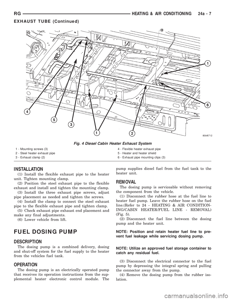
(1) Install the flexible exhaust pipe to the heater
unit. Tighten mounting clamp.
(2) Position the steel exhaust pipe to the flexible
exhaust and install and tighten the mounting clamp.
(3) Install the three exhaust pipe screws, adjust
pipe placement as needed and tighten the screws.
(4) Install the clamp to connect the steel exhaust
pipe to the flexible exhaust pipe and tighten clamp.
(5) Check exhaust pipe exhaust end placement and
make any final adjustments.
(6) Lower vehicle from lift.
FUEL DOSING PUMP
DESCRIPTION
The dosing pump is a combined delivery, dosing
and shut-off system for the fuel supply to the heater
from the vehicles fuel tank.
OPERATION
The dosing pump is an electrically operated pump
that receives its operation instructions from the sup-
plemental heater electronic control module. Thepump supplies diesel fuel from the fuel tank to the
heater unit.
REMOVAL
The dosing pump is serviceable without removing
the component from the vehicle.
(1) Disconnect the rubber hose at the fuel line to
heater fuel pump. Leave the rubber hose on the fuel
line.(Refer to 24 - HEATING & AIR CONDITION-
ING/CABIN HEATER/FUEL LINE - REMOVAL)
(Fig. 5).
(2) Disconnect the fuel line between the dosing
pump and the heater unit.
NOTE: Position and retain heater fuel line to pre-
vent fuel leakage while servicing dosing pump.
NOTE: Utilize an approved fuel storage container to
catch any residual fuel.
(3) Disconnect the electrical connector to the fuel
pump by depressing the integral spring and pulling
the connector away from the pump.
(4) Remove the dosing pump from the rubber iso-
lation.
Fig. 4 Diesel Cabin Heater Exhaust System
1 - Mounting screws (3)
2 - Steel heater exhaust pipe
3 - Exhaust clamp (2)4 - Flexible heater exhaust pipe
5 - Heater and heater shield
6 - Exhaust pipe mounting clips (3)
RGHEATING & AIR CONDITIONING24a-7
EXHAUST TUBE (Continued)