2001 CHRYSLER VOYAGER fuel pressure
[x] Cancel search: fuel pressurePage 1218 of 4284
TABLE OF CONTENTS - Continued
SERIAL LINK EXTERNAL FAULT.........................................216
ROLLING CODE FAILURE...............................................218
VIN MISMATCH........................................................218
TRANSPONDER COMMUNICATION FAILURE..............................220
TRANSPONDER CYCLIC REDUNDANCY CHECK (CRC) FAILURE.............220
TRANSPONDER ID MISMATCH..........................................220
TRANSPONDER RESPONSE MISMATCH..................................220
VERIFICATION TESTS
VERIFICATION TESTS..................................................223
8.0 COMPONENT LOCATIONS..............................................227
8.1CONTROL MODULES.............................................227
8.2CONTROLS AND SOLENOIDS......................................227
8.3DATA LINK CONNECTOR..........................................227
8.4FUEL SYSTEM...................................................228
8.5RELAYS.........................................................228
8.6SENSORS.......................................................229
8.7SWITCHES......................................................230
9.0 CONNECTOR PINOUTS................................................231
A/C COMPRESSOR CLUTCH - LT. GRAY 2 WAY............................231
A/C PRESSURE SENSOR - GRAY 4 WAY..................................231
ACCELERATOR PEDAL POSITION SENSOR (DIESEL) - BLACK 10 WAY........231
BATTERY TEMPERATURE SENSOR (DIESEL) - BLACK 2 WAY................231
BOOST PRESSURE SENSOR (DIESEL) - BLACK 4 WAY.....................232
BRAKE LAMP SWITCH - BLACK 6 WAY...................................232
CAMSHAFT POSITION SENSOR (DIESEL) - BLACK 3 WAY...................232
CLUTCH PEDAL UPSTOP SWITCH (DIESEL) - RED 2 WAY...................232
CRANKSHAFT POSITION SENSOR (DIESEL) - BLACK 3 WAY................232
DATA LINK CONNECTOR - BLACK 16 WAY................................233
EGR SOLENOID (DIESEL) - LT. GRAY 2 WAY...............................233
ENGINE CONTROL MODULE C1 (DIESEL) - BLACK 81 WAY..................234
ENGINE CONTROL MODULE C1 (DIESEL) - BLACK 81 WAY..................235
ENGINE CONTROL MODULE C2 (DIESEL) - BLACK 40 WAY..................236
ENGINE COOLANT TEMP SENSOR (DIESEL) - BLUE 2 WAY.................236
ENGINE OIL PRESSURE SENSOR (DIESEL) - BLACK 3 WAY.................237
ENGINE OIL TEMPERATURE SENSOR (DIESEL) - BLACK 2 WAY.............237
FUEL HEATER (DIESEL) - BLACK 2 WAY..................................237
FUEL INJECTOR NO. 1 (DIESEL) - BLACK 2 WAY...........................237
FUEL INJECTOR NO. 2 (DIESEL) - BLACK 2 WAY...........................237
FUEL INJECTOR NO. 3 (DIESEL) - BLACK 2 WAY...........................238
FUEL INJECTOR NO. 4 (DIESEL) - BLACK 2 WAY...........................238
FUEL PRESSURE SENSOR (DIESEL) - BLACK 3 WAY.......................238
FUEL PRESSURE SOLENOID (DIESEL) - BLACK 2 WAY.....................238
GENERATOR - BLACK 2 WAY...........................................238
GLOW PLUG RELAY (DIESEL) - BLACK 4 WAY.............................239
INTELLIGENT POWER MODULE C3 (DIESEL) - YELLOW/RED 20 WAY.........239
LEFT SPEED CONTROL SWITCH - WHITE 2 WAY..........................239
LIFT PUMP MOTOR (DIESEL) - BLACK 2 WAY..............................239
MASS AIR FLOW SENSOR (DIESEL) - ORANGE 5 WAY......................240
v
Page 1223 of 4284
check the shared circuits for possible problems
before continuing (i.e. Sensor Grounds or 5-Volt
Supply circuits). Refer to the appropriate wiring
diagrams to identify shared circuits.
MASS AIR FLOW SENSOR SIGNAL VOLTAGE
TOO HIGH
MASS AIR FLOW SENSOR SIGNAL VOLTAGE
TOO LOW
MASS AIR FLOW SENSOR SUPPLY VOLTAGE
TOO HIGH OR LOW
MASS AIR FLOW SENSOR PLAUSIBILITY
MASS AIR FLOW SENSOR SIGNAL PLAUSI-
BILITY POSITIVE AREA
BAROMETRIC PRESSURE CIRCUIT SIGNAL
VOLTAGE TOO HIGH
BAROMETRIC PRESSURE CIRCUIT SIGNAL
VOLTAGE TOO LOW
INTAKE AIR TEMP SENSOR SIGNAL VOLT-
AGE TOO HIGH
INTAKE AIR TEMP SENSOR SIGNAL VOLT-
AGE TOO LOW
ENGINE COOLANT TEMP SENSOR SIGNAL
VOLTAGE TOO HIGH
ENGINE COOLANT TEMP SENSOR SIGNAL
VOLTAGE TOO LOW
FUEL PRESS SENSOR CIRCUIT MALF SIG-
NAL VOLTAGE TOO HIGH
FUEL PRESS SENSOR CIRCUIT MALF SIG-
NAL VOLTAGE TOO LOW
FUEL PRESS SENSOR CIRCUIT MALF SUP-
PLY VOLTAGE TOO HIGH OR LOW
OIL TEMP SENSOR CIRCUIT MALF SIGNAL
VOLTAGE TOO HIGH
OIL TEMP SENSOR CIRCUIT MALF SIGNAL
VOLTAGE TOO LOW
CYLINDER 1-INJECTOR CIRCUIT OVERCUR-
RENT HIGH SIDE
CYLINDER 1-INJECTOR CIRCUIT OVERCUR-
RENT LOW SIDE
CYLINDER 1-INJECTOR CIRCUIT LOAD
DROP
CYLINDER 1-INJECTOR CIRCUIT CURRENT
DECREASE
CYLINDER 2-INJECTOR CIRCUIT OVERCUR-
RENT HIGH SIDE
CYLINDER 2-INJECTOR CIRCUIT OVERCUR-
RENT LOW SIDE
CYLINDER 2-INJECTOR CIRCUIT LOAD
DROP
CYLINDER 2-INJECTOR CIRCUIT CURRENT
DECREASE
CYLINDER 3-INJECTOR CIRCUIT OVERCUR-
RENT HIGH SIDE
CYLINDER 3-INJECTOR CIRCUIT OVERCUR-
RENT LOW SIDE
CYLINDER 3-INJECTOR CIRCUIT LOAD
DROPCYLINDER 3-INJECTOR CIRCUIT CURRENT
DECREASE
CYLINDER 4-INJECTOR CIRCUIT OVERCUR-
RENT HIGH SIDE
CYLINDER 4-INJECTOR CIRCUIT OVERCUR-
RENT LOW SIDE
CYLINDER 4-INJECTOR CIRCUIT LOAD
DROP
CYLINDER 4-INJECTOR CIRCUIT CURRENT
DECREASE
BOOST PRESSURE SENSOR SIGNAL VOLT-
AGE TOO HIGH
BOOST PRESSURE SENSOR SIGNAL VOLT-
AGE TOO LOW
BOOST PRESSURE SENSOR SUPPLY VOLT-
AGE TOO HIGH OR LOW
BOOST PRESSURE SENSOR PLAUSIBILITY
CKP POSITION SENSOR CIRCUIT OVER-
SPEED RECOGNITION
CKP POSITION SENSOR CIRCUIT DYNAMIC
PLAUSIBILITY
CKP POSITION SENSOR CIRCUIT STATIC
PLAUSIBILITY
CMP POSITION SENSOR CIRCUIT CMP/CKP
SYNC FAILURE
CMP POSITION SENSOR CIRCUIT DYNAMIC
PLAUSIBILITY
CMP POSITION SENSOR CIRCUIT STATIC
PLAUSIBILITY
CMP POSITION SENSOR CIRCUIT SIGNAL
FREQUENCY TOO HIGH
CMP POSITION SENSOR CIRCUIT FUEL
SHUT-OFF ACTIVATED
GLOW PLUG CIRCUIT A SHORT CIRCUIT
GLOW PLUG CIRCUIT A OPEN CIRCUIT
EGR SOLENOID CIRCUIT OPEN CIRCUIT
EGR SOLENOID CIRCUIT SHORT CIRCUIT
EGR SOLENOID CIRCUIT IMPROPER FLOW
FAN 1 CONTROL CIRCUIT OPEN CIRCUIT
FAN 1 CONTROL CIRCUIT SHORT CIRCUIT
FAN 2 CONTROL CIRCUIT OPEN CIRCUIT
FAN 2 CONTROL CIRCUIT SHORT CIRCUIT
VEHICLE SPEED SENSOR SIGNAL VOLTAGE
TOO HIGH
VEHICLE SPEED SENSOR FREQUENCY TOO
HIGH
VEHICLE SPEED SENSOR HIGH LEVEL DU-
RATION
VEHICLE SPEED SENSOR PLAUSIBILITY
BATTERY TEMP SENSOR SIGNAL VOLTAGE
TOO HIGH
BATTERY TEMP SENSOR SIGNAL VOLTAGE
TOO LOW
OIL PRESS SENSOR CKT MALF PLAUSIBIL-
ITY
4
GENERAL INFORMATION
Page 1224 of 4284
A/C PRESSURE SENSOR CIRCUIT SIGNAL
VOLTAGE TOO HIGH
A/C PRESSURE SENSOR CIRCUIT SIGNAL
VOLTAGE TOO LOW
A/C PRESSURE SENSOR CIRCUIT SUPPLY
VOLTAGE TOO HIGH OR LOW
A/C PRESSURE SENSOR CIRCUIT PLAUSI-
BILITY
SYSTEM VOLTAGE TOO HIGH
SYSTEM VOLTAGE TOO LOW
S/C SWITCH SIGNAL CIRCUIT SIGNAL VOLT-
AGE TOO HIGH
S/C SWITCH SIGNAL CIRCUIT SIGNAL VOLT-
AGE TOO LOW
S/C SWITCH SIGNAL CIRCUIT PLAUSIBILITY
ECM ERROR RECOVERY HAS OCCURRED
ECM ERROR REDUNDANT OVERRUN MONI-
TORING
ECM ERROR GATE ARRAY - QUANTITY STOP
ECM ERROR GATE ARRAY - COMMUNICA-
TION
ECM ERROR - COMMUNICATION NOT VERI-
FIED
STARTER RELAY CIRCUIT OPEN CIRCUIT
STARTER RELAY CIRCUIT SHORT CIRCUIT
GENERATOR FIELD CONTROL MALF BAT-
TERY VOLTAGE TOO HIGH
GENERATOR FIELD CONTROL MALF BAT-
TERY VOLTAGE TOO LOW
GENERATOR FIELD CONTROL MALF OPEN
CIRCUIT
GENERATOR FIELD CONTROL MALF SHORT
CIRCUIT
GENERATOR FIELD CONTROL MALF
CHARGING VOLTS TOO LOW
GENERATOR FIELD CONTROL MALF BAT-
TERY VOLTAGE DEVIATION TOO HIGH
GENERATOR FIELD CONTROL MALF BAT-
TERY VOLTAGE DEVIATION TOO LOW
GENERATOR FIELD CONTROL MALF UN-
STABLE CURRENT
SENSOR REFERENCE VOLTAGE A CKT VOLT-
AGE TOO HIGH
SENSOR REFERENCE VOLTAGE A CKT VOLT-
AGE TOO LOW
SENSOR REFERENCE VOLTAGE B CKT
VOLTAGE TOO HIGH
SENSOR REFERENCE VOLTAGE B CKT
VOLTAGE TOO LOW
A/C CLUTCH RELAY CIRCUIT OPEN CIRCUIT
A/C CLUTCH RELAY CIRCUIT SHORT CIR-
CUIT
ECM/PCM RELAY CONTROL CIRCUIT SHUTS
OFF TOO EARLY
ECM/PCM RELAY CONTROL CIRCUIT SHUTS
OFF TOO LATE
BRAKE SWITCH SIGNAL CIRCUITS INCOR-
RECT CAN MESSAGEBRAKE SWITCH SIGNAL CIRCUITS PLAUSI-
BILITY WITH REDUNDANT CONTACT
BRAKE SWITCH SIGNAL CIRCUITS PLAUSI-
BILITY WITH REDUNDANT CONTACT AFTER
INITIALIZATION
CLUTCH UPSTOP SWITCH PERF PLAUSIBIL-
ITY
CLUTCH UPSTOP SWITCH PERF PLAUSIBIL-
ITY WITH P/N SWITCH
FUEL RAIL PRESSURE MALFUNCTION
PRESSURE TOO HIGH - LIMITATION
FUEL RAIL PRESSURE MALFUNCTION
PRESSURE TOO LOW
FUEL RAIL PRESSURE MALFUNCTION SO-
LENOID OPEN
FUEL RAIL PRESSURE MALFUNCTION
LEAKAGE DETECTED
FUEL PRESSURE SOLENOID OPEN CIRCUIT
FUEL PRESSURE SOLENOID SHORT CIR-
CUIT
FUEL PRESSURE SOLENOID PLAUSIBILITY
IN AFTER-RUN
CALCULATED INJECTOR VOLTAGE - VOLT-
AGE 1 TOO LOW
CALCULATED INJECTOR VOLTAGE - VOLT-
AGE 2 TOO LOW
BATTERY SENSE LINE 1 VOLTAGE TOO
HIGH
BATTERY SENSE LINE 1 VOLTAGE TOO LOW
FUEL PRESS REG CURRENT CONTROL SIG-
NAL TOO HIGH
FUEL PRESS REG CURRENT CONTROL SIG-
NAL TOO LOW
GENERATOR FIELD CURRENT TOO HIGH
GENERATOR FIELD CURRENT TOO LOW
CAPACITOR VOLTAGE 1 VOLTAGE TOO HIGH
CAPACITOR VOLTAGE 1 VOLTAGE TOO LOW
CAPACITOR VOLTAGE 2 VOLTAGE TOO HIGH
CAPACITOR VOLTAGE 2 VOLTAGE TOO LOW
IGNITION SWITCH PLAUSIBILITY
AFTER RUN SHUT OFF ERROR - ZERO
QUANTITY
AFTERRUN SHUT OFF ERROR - INJ. POWER-
STAGE
VOLTAGE REGULATOR SIGNAL VOLTAGE
TOO HIGH
VOLTAGE REGULATOR SIGNAL VOLTAGE
TOO LOW
MIL/DIAG LAMP VIA J1850 BUS IN FRAME
RESPONSE ERROR
MIL/DIAG LAMP VIA J1850 BUS - STATUS
ERROR
J1850 COMMUNICATION BUS SHORT TO
VOLTAGE
J1850 COMMUNICATION BUS SHORT TO
GROUND
J1850 COMMUNICATION BUS TRANSMIT
BUFFER OVERRUN
5
GENERAL INFORMATION
Page 1227 of 4284
4.3 WARNINGS AND CAUTIONS
4.3.1 ROAD TEST WARNINGS
Some complaints will require a test drive as part
of the repair verification procedure. The purpose of
the test drive is to try to duplicate the diagnostic
code or symptom condition.
CAUTION: BEFORE ROAD TESTING A
VEHICLE, BE SURE THAT ALL
COMPONENTS ARE REASSEMBLED. DUR-
ING THE TEST DRIVE, DO NOT HANG THE
DRBIIITFROM THE REAR VIEW MIRROR. DO
NOT ATTEMPT TO READ THE DRBIIITWHILE
DRIVING. HAVE AN ASSISTANT AVAILABLE
TO OPERATE THE DRBIIIT.
4.3.2 VEHICLE DAMAGE CAUTIONS
Before disconnecting any control module, make
sure the ignition is off. Failure to do so could
damage the module. When testing voltage or circuit
integrity at any control module, use the terminal
side (not the wire end) of the harness connector. Do
not probe through the insulation; this will damage
it and eventually cause it to fail because of corro-
sion.
Be careful when performing electrical test so as to
prevent accidental shorting of terminals. Such a
mistake can damage fuses or components. Also, a
second code could be set, making diagnosis of the
original problem more difficult.
5.0 REQUIRED TOOLS AND
EQUIPMENT
DRBIIIt(diagnostic read-out box) scan tool
vacuum gauge
ammeter
ohmmeter
jumper wires and probes
oscilloscope
6.0 GLOSSARY OF TERMS
A/Cair conditioning
APPaccelerator pedal position (sensor)
backfire,
popbackfuel ignites in either the intake or
the exhaust system
BCMbody control module
BPboost pressure (sensor)CKPcrankshaft position (sensor)
CMPcamshaft position (sensor)
cuts out,
missesa steady pulsation or the inability of
the engine to maintain a consistent
rpm
DLCdata link connector
detona-
tion,
spark
knocka mild to severe ping, especially un-
der loaded engine conditions
ECMengine control module
ECTengine coolant temperature (sensor)
EGRexhaust gas recirculation
(solenoid/valve)
hard
startthe engine takes longer than usual
to start, even though it is able to
crank at normal speed.
IATintake air temperature (sensor)
IPMintelligent power module
lack of
power,
sluggishthe engine power output has been
reduced
MAFmass air flow (sensor)
MILmalfunction indicator lamp
msmillisecond(s)
PDCpower distribution center
poor fuel
economythere is significantly less fuel mile-
age than other vehicles of the same
design and configuration
runs
rough/
unstable
idlethe engine runs unevenly at idle
causing the engine to shake if it is
severe enough
S/Cspeed control
SKIMsentry key immobilizer module
SKISsentry key immobilizer system
start and
stallThe engine starts but immediately
dies (stalls)
surgeengine rpm fluctuation without cor-
responding change in accelerator
pedal position
SRCsignal range check
WIFwater in fuel (sensor)
VSSvehicle speed sensor
8
GENERAL INFORMATION
Page 1237 of 4284
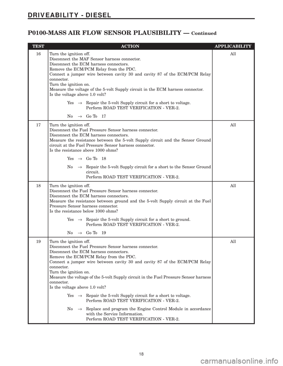
TEST ACTION APPLICABILITY
16 Turn the ignition off.
Disconnect the MAF Sensor harness connector.
Disconnect the ECM harness connectors.
Remove the ECM/PCM Relay from the PDC.
Connect a jumper wire between cavity 30 and cavity 87 of the ECM/PCM Relay
connector.
Turn the ignition on.
Measure the voltage of the 5-volt Supply circuit in the ECM harness connector.
Is the voltage above 1.0 volt?All
Ye s®Repair the 5-volt Supply circuit for a short to voltage.
Perform ROAD TEST VERIFICATION - VER-2.
No®Go To 17
17 Turn the ignition off.
Disconnect the Fuel Pressure Sensor harness connector.
Disconnect the ECM harness connectors.
Measure the resistance between the 5-volt Supply circuit and the Sensor Ground
circuit at the Fuel Pressure Sensor harness connector.
Is the resistance above 1000 ohms?All
Ye s®Go To 18
No®Repair the 5-volt Supply circuit for a short to the Sensor Ground
circuit.
Perform ROAD TEST VERIFICATION - VER-2.
18 Turn the ignition off.
Disconnect the Fuel Pressure Sensor harness connector.
Disconnect the ECM harness connectors.
Measure the resistance between ground and the 5-volt Supply circuit at the Fuel
Pressure Sensor harness connector.
Is the resistance below 1000 ohms?All
Ye s®Repair the 5-volt Supply circuit for a short to ground.
Perform ROAD TEST VERIFICATION - VER-2.
No®Go To 19
19 Turn the ignition off.
Disconnect the Fuel Pressure Sensor harness connector.
Disconnect the ECM harness connectors.
Remove the ECM/PCM Relay from the PDC.
Connect a jumper wire between cavity 30 and cavity 87 of the ECM/PCM Relay
connector.
Turn the ignition on.
Measure the voltage of the 5-volt Supply circuit in the Fuel Pressure Sensor harness
connector.
Is the voltage above 1.0 volt?All
Ye s®Repair the 5-volt Supply circuit for a short to voltage.
Perform ROAD TEST VERIFICATION - VER-2.
No®Replace and program the Engine Control Module in accordance
with the Service Information.
Perform ROAD TEST VERIFICATION - VER-2.
18
DRIVEABILITY - DIESEL
P0100-MASS AIR FLOW SENSOR PLAUSIBILITY ÐContinued
Page 1253 of 4284
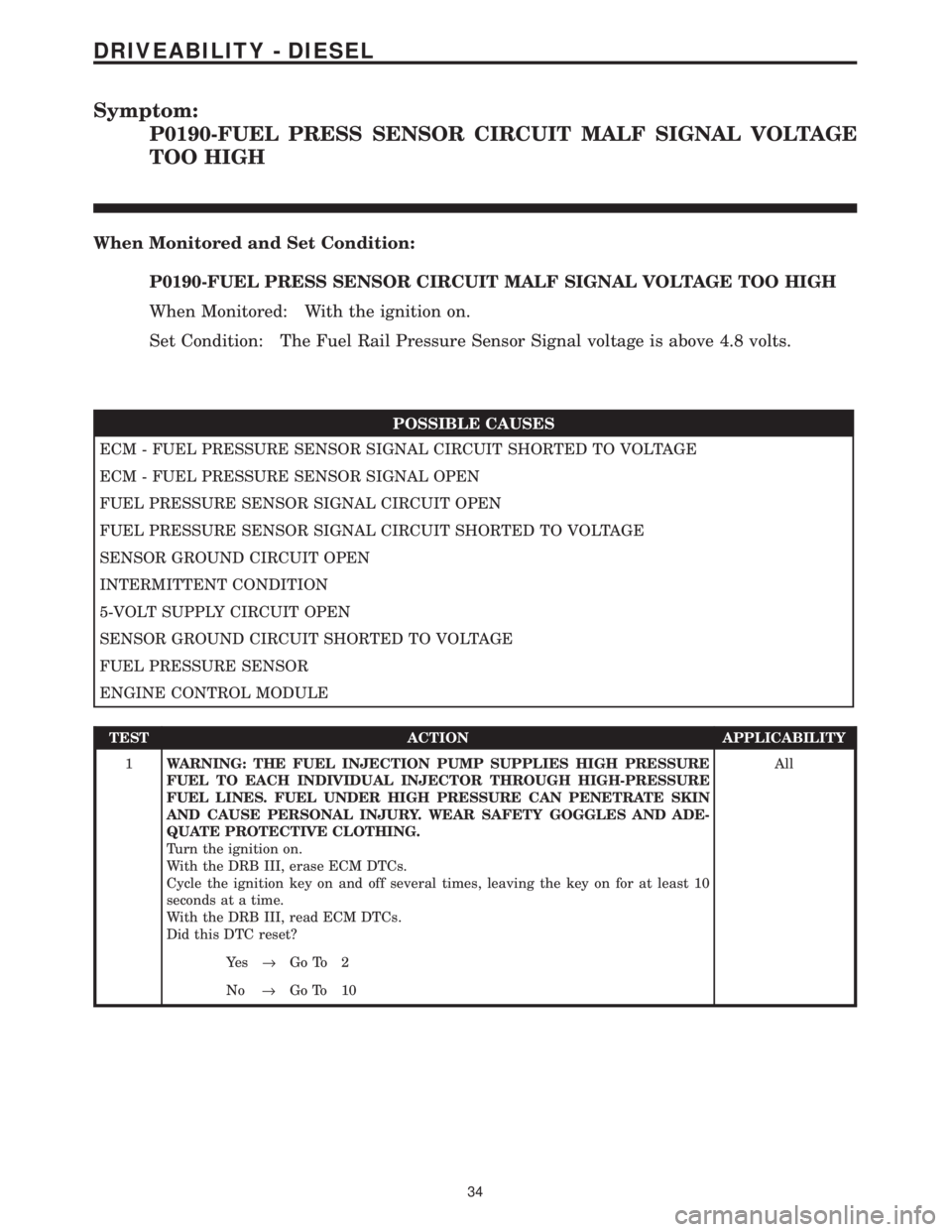
Symptom:
P0190-FUEL PRESS SENSOR CIRCUIT MALF SIGNAL VOLTAGE
TOO HIGH
When Monitored and Set Condition:
P0190-FUEL PRESS SENSOR CIRCUIT MALF SIGNAL VOLTAGE TOO HIGH
When Monitored: With the ignition on.
Set Condition: The Fuel Rail Pressure Sensor Signal voltage is above 4.8 volts.
POSSIBLE CAUSES
ECM - FUEL PRESSURE SENSOR SIGNAL CIRCUIT SHORTED TO VOLTAGE
ECM - FUEL PRESSURE SENSOR SIGNAL OPEN
FUEL PRESSURE SENSOR SIGNAL CIRCUIT OPEN
FUEL PRESSURE SENSOR SIGNAL CIRCUIT SHORTED TO VOLTAGE
SENSOR GROUND CIRCUIT OPEN
INTERMITTENT CONDITION
5-VOLT SUPPLY CIRCUIT OPEN
SENSOR GROUND CIRCUIT SHORTED TO VOLTAGE
FUEL PRESSURE SENSOR
ENGINE CONTROL MODULE
TEST ACTION APPLICABILITY
1WARNING: THE FUEL INJECTION PUMP SUPPLIES HIGH PRESSURE
FUEL TO EACH INDIVIDUAL INJECTOR THROUGH HIGH-PRESSURE
FUEL LINES. FUEL UNDER HIGH PRESSURE CAN PENETRATE SKIN
AND CAUSE PERSONAL INJURY. WEAR SAFETY GOGGLES AND ADE-
QUATE PROTECTIVE CLOTHING.
Turn the ignition on.
With the DRB III, erase ECM DTCs.
Cycle the ignition key on and off several times, leaving the key on for at least 10
seconds at a time.
With the DRB III, read ECM DTCs.
Did this DTC reset?All
Ye s®Go To 2
No®Go To 10
34
DRIVEABILITY - DIESEL
Page 1254 of 4284
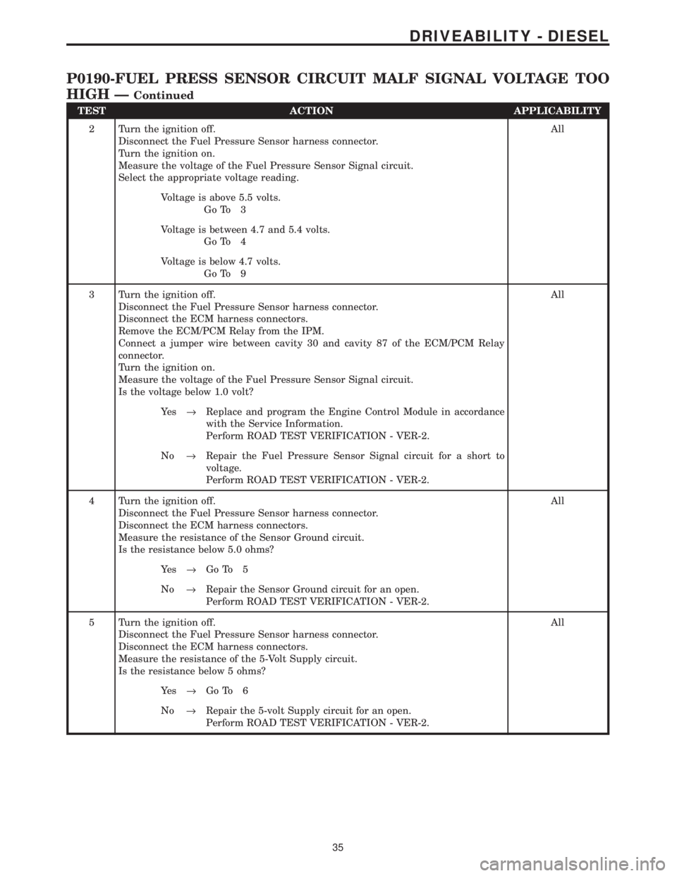
TEST ACTION APPLICABILITY
2 Turn the ignition off.
Disconnect the Fuel Pressure Sensor harness connector.
Turn the ignition on.
Measure the voltage of the Fuel Pressure Sensor Signal circuit.
Select the appropriate voltage reading.All
Voltage is above 5.5 volts.
Go To 3
Voltage is between 4.7 and 5.4 volts.
Go To 4
Voltage is below 4.7 volts.
Go To 9
3 Turn the ignition off.
Disconnect the Fuel Pressure Sensor harness connector.
Disconnect the ECM harness connectors.
Remove the ECM/PCM Relay from the IPM.
Connect a jumper wire between cavity 30 and cavity 87 of the ECM/PCM Relay
connector.
Turn the ignition on.
Measure the voltage of the Fuel Pressure Sensor Signal circuit.
Is the voltage below 1.0 volt?All
Ye s®Replace and program the Engine Control Module in accordance
with the Service Information.
Perform ROAD TEST VERIFICATION - VER-2.
No®Repair the Fuel Pressure Sensor Signal circuit for a short to
voltage.
Perform ROAD TEST VERIFICATION - VER-2.
4 Turn the ignition off.
Disconnect the Fuel Pressure Sensor harness connector.
Disconnect the ECM harness connectors.
Measure the resistance of the Sensor Ground circuit.
Is the resistance below 5.0 ohms?All
Ye s®Go To 5
No®Repair the Sensor Ground circuit for an open.
Perform ROAD TEST VERIFICATION - VER-2.
5 Turn the ignition off.
Disconnect the Fuel Pressure Sensor harness connector.
Disconnect the ECM harness connectors.
Measure the resistance of the 5-Volt Supply circuit.
Is the resistance below 5 ohms?All
Ye s®Go To 6
No®Repair the 5-volt Supply circuit for an open.
Perform ROAD TEST VERIFICATION - VER-2.
35
DRIVEABILITY - DIESEL
P0190-FUEL PRESS SENSOR CIRCUIT MALF SIGNAL VOLTAGE TOO
HIGH Ð
Continued
Page 1255 of 4284
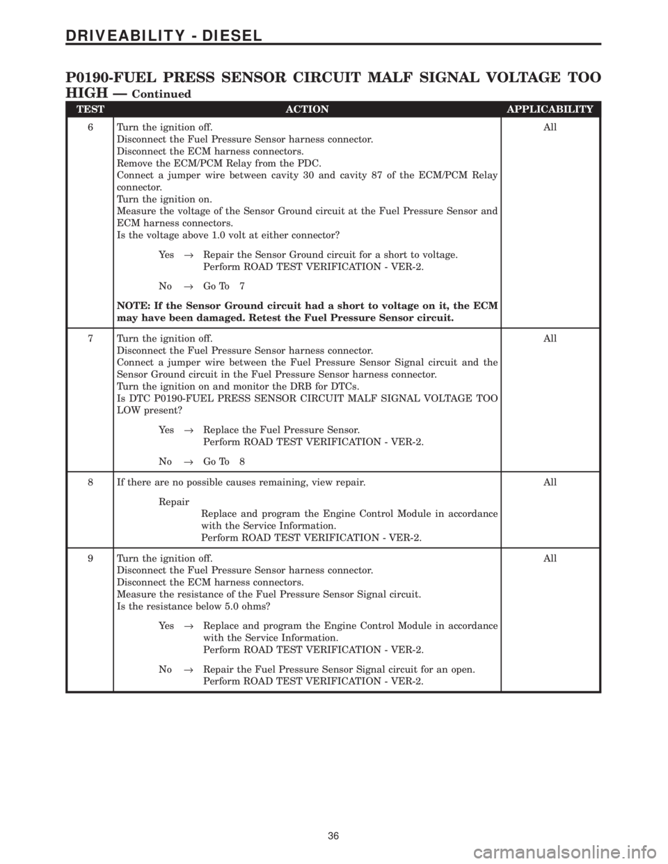
TEST ACTION APPLICABILITY
6 Turn the ignition off.
Disconnect the Fuel Pressure Sensor harness connector.
Disconnect the ECM harness connectors.
Remove the ECM/PCM Relay from the PDC.
Connect a jumper wire between cavity 30 and cavity 87 of the ECM/PCM Relay
connector.
Turn the ignition on.
Measure the voltage of the Sensor Ground circuit at the Fuel Pressure Sensor and
ECM harness connectors.
Is the voltage above 1.0 volt at either connector?All
Ye s®Repair the Sensor Ground circuit for a short to voltage.
Perform ROAD TEST VERIFICATION - VER-2.
No®Go To 7
NOTE: If the Sensor Ground circuit had a short to voltage on it, the ECM
may have been damaged. Retest the Fuel Pressure Sensor circuit.
7 Turn the ignition off.
Disconnect the Fuel Pressure Sensor harness connector.
Connect a jumper wire between the Fuel Pressure Sensor Signal circuit and the
Sensor Ground circuit in the Fuel Pressure Sensor harness connector.
Turn the ignition on and monitor the DRB for DTCs.
Is DTC P0190-FUEL PRESS SENSOR CIRCUIT MALF SIGNAL VOLTAGE TOO
LOW present?All
Ye s®Replace the Fuel Pressure Sensor.
Perform ROAD TEST VERIFICATION - VER-2.
No®Go To 8
8 If there are no possible causes remaining, view repair. All
Repair
Replace and program the Engine Control Module in accordance
with the Service Information.
Perform ROAD TEST VERIFICATION - VER-2.
9 Turn the ignition off.
Disconnect the Fuel Pressure Sensor harness connector.
Disconnect the ECM harness connectors.
Measure the resistance of the Fuel Pressure Sensor Signal circuit.
Is the resistance below 5.0 ohms?All
Ye s®Replace and program the Engine Control Module in accordance
with the Service Information.
Perform ROAD TEST VERIFICATION - VER-2.
No®Repair the Fuel Pressure Sensor Signal circuit for an open.
Perform ROAD TEST VERIFICATION - VER-2.
36
DRIVEABILITY - DIESEL
P0190-FUEL PRESS SENSOR CIRCUIT MALF SIGNAL VOLTAGE TOO
HIGH Ð
Continued