2001 CHRYSLER VOYAGER fuel pressure
[x] Cancel search: fuel pressurePage 1567 of 4284
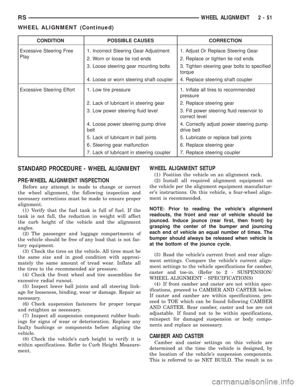
CONDITION POSSIBLE CAUSES CORRECTION
Excessive Steering Free
Play1. Incorrect Steering Gear Adjustment 1. Adjust Or Replace Steering Gear
2. Worn or loose tie rod ends 2. Replace or tighten tie rod ends
3. Loose steering gear mounting bolts 3. Tighten steering gear bolts to specified
torque
4. Loose or worn steering shaft coupler 4. Replace steering shaft coupler
Excessive Steering Effort 1. Low tire pressure 1. Inflate all tires to recommended
pressure
2. Lack of lubricant in steering gear 2. Replace steering gear
3. Low power steering fluid level 3. Fill power steering fluid reservoir to
correct level
4. Loose power steering pump drive
belt4. Correctly adjust power steering pump
drive belt
5. Lack of lubricant in ball joints 5. Lubricate or replace ball joints
6. Steering gear malfunction 6. Replace steering gear
7. Lack of lubricant in steering coupler 7. Replace steering coupler
STANDARD PROCEDURE - WHEEL ALIGNMENT
PRE-WHEEL ALIGNMENT INSPECTION
Before any attempt is made to change or correct
the wheel alignment, the following inspection and
necessary corrections must be made to ensure proper
alignment.
(1) Verify that the fuel tank is full of fuel. If the
tank is not full, the reduction in weight will affect
the curb height of the vehicle and the alignment
angles.
(2) The passenger and luggage compartments of
the vehicle should be free of any load that is not fac-
tory equipment.
(3) Check the tires on the vehicle. All tires must be
the same size and in good condition with approxi-
mately the same amount of tread wear. Inflate all
the tires to the recommended air pressure.
(4) Check the front wheel and tire assemblies for
excessive radial runout.
(5) Inspect lower ball joints and all steering link-
age for looseness, binding, wear or damage. Repair as
necessary.
(6) Check suspension fasteners for proper torque
and retighten as necessary.
(7) Inspect all suspension component rubber bush-
ings for signs of wear or deterioration. Replace any
faulty bushings or components before aligning the
vehicle.
(8) Check the vehicle's curb height to verify it is
within specifications. Refer to Curb Height Measure-
ment.
WHEEL ALIGNMENT SETUP
(1) Position the vehicle on an alignment rack.
(2) Install all required alignment equipment on
the vehicle per the alignment equipment manufactur-
er's instructions. On this vehicle, a four-wheel align-
ment is recommended.
NOTE: Prior to reading the vehicle's alignment
readouts, the front and rear of vehicle should be
jounced. Induce jounce (rear first, then front) by
grasping the center of the bumper and jouncing
each end of vehicle an equal number of times. The
bumper should always be released when vehicle is
at the bottom of the jounce cycle.
(3) Read the vehicle's current front and rear align-
ment settings. Compare the vehicle's current align-
ment settings to the vehicle specifications for camber,
caster and toe-in. (Refer to 2 - SUSPENSION/
WHEEL ALIGNMENT - SPECIFICATIONS)
(4) If front camber and caster are not within spec-
ifications, proceed to CAMBER AND CASTER below.
If caster and camber are within specifications, pro-
ceed to TOE which can be found following CAMBER
AND CASTER. Rear camber, caster and toe are not
adjustable. If found not to be within specifications,
reinspect for damaged suspension or body compo-
nents and replace as necessary.
CAMBER AND CASTER
Camber and caster settings on this vehicle are
determined at the time the vehicle is designed, by
the location of the vehicle's suspension components.
This is referred to as NET BUILD. The result is no
RSWHEEL ALIGNMENT2-51
WHEEL ALIGNMENT (Continued)
Page 1570 of 4284
CAUTION: Do not twist front inner tie rod to steer-
ing gear rubber boots during front wheel Toe
adjustment.
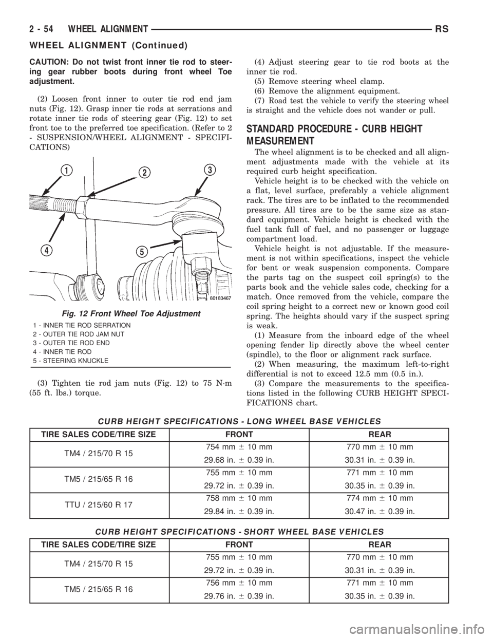
(2) Loosen front inner to outer tie rod end jam
nuts (Fig. 12). Grasp inner tie rods at serrations and
rotate inner tie rods of steering gear (Fig. 12) to set
front toe to the preferred toe specification. (Refer to 2
- SUSPENSION/WHEEL ALIGNMENT - SPECIFI-
CATIONS)
(3) Tighten tie rod jam nuts (Fig. 12) to 75 N´m
(55 ft. lbs.) torque.(4) Adjust steering gear to tie rod boots at the
inner tie rod.
(5) Remove steering wheel clamp.
(6) Remove the alignment equipment.
(7)
Road test the vehicle to verify the steering wheel
is straight and the vehicle does not wander or pull.
STANDARD PROCEDURE - CURB HEIGHT
MEASUREMENT
The wheel alignment is to be checked and all align-
ment adjustments made with the vehicle at its
required curb height specification.
Vehicle height is to be checked with the vehicle on
a flat, level surface, preferably a vehicle alignment
rack. The tires are to be inflated to the recommended
pressure. All tires are to be the same size as stan-
dard equipment. Vehicle height is checked with the
fuel tank full of fuel, and no passenger or luggage
compartment load.
Vehicle height is not adjustable. If the measure-
ment is not within specifications, inspect the vehicle
for bent or weak suspension components. Compare
the parts tag on the suspect coil spring(s) to the
parts book and the vehicle sales code, checking for a
match. Once removed from the vehicle, compare the
coil spring height to a correct new or known good coil
spring. The heights should vary if the suspect spring
is weak.
(1) Measure from the inboard edge of the wheel
opening fender lip directly above the wheel center
(spindle), to the floor or alignment rack surface.
(2) When measuring, the maximum left-to-right
differential is not to exceed 12.5 mm (0.5 in.).
(3) Compare the measurements to the specifica-
tions listed in the following CURB HEIGHT SPECI-
FICATIONS chart.
CURB HEIGHT SPECIFICATIONS - LONG WHEEL BASE VEHICLES
TIRE SALES CODE/TIRE SIZE FRONT REAR
TM4 / 215/70 R 15754 mm610 mm 770 mm610 mm
29.68 in.60.39 in. 30.31 in.60.39 in.
TM5 / 215/65 R 16755 mm610 mm 771 mm610 mm
29.72 in.60.39 in. 30.35 in.60.39 in.
TTU / 215/60 R 17758 mm610 mm 774 mm610 mm
29.84 in.60.39 in. 30.47 in.60.39 in.
CURB HEIGHT SPECIFICATIONS - SHORT WHEEL BASE VEHICLES
TIRE SALES CODE/TIRE SIZE FRONT REAR
TM4 / 215/70 R 15755 mm610 mm 770 mm610 mm
29.72 in.60.39 in. 30.31 in.60.39 in.
TM5 / 215/65 R 16756 mm610 mm 771 mm610 mm
29.76 in.60.39 in. 30.35 in.60.39 in.
Fig. 12 Front Wheel Toe Adjustment
1 - INNER TIE ROD SERRATION
2 - OUTER TIE ROD JAM NUT
3 - OUTER TIE ROD END
4 - INNER TIE ROD
5 - STEERING KNUCKLE
2 - 54 WHEEL ALIGNMENTRS
WHEEL ALIGNMENT (Continued)
Page 1575 of 4284
WHEEL ALIGNMENT
TABLE OF CONTENTS
page page
WHEEL ALIGNMENT
STANDARD PROCEDURE...................3CURB HEIGHT MEASUREMENT............3
WHEEL ALIGNMENT
STANDARD PROCEDURE - CURB HEIGHT
MEASUREMENT
The wheel alignment is to be checked and all align-
ment adjustments made with the vehicle at its
required curb height specification.
Vehicle height is to be checked with the vehicle on
a flat, level surface, preferably a vehicle alignment
rack. The tires are to be inflated to the recommended
pressure. All tires are to be the same size as stan-
dard equipment. Vehicle height is checked with the
fuel tank full of fuel, and no passenger or luggage
compartment load.
Vehicle height is not adjustable. If the measure-
ment is not within specifications, inspect the vehiclefor bent or weak suspension components. Compare
the parts tag on the suspect coil spring(s) to the
parts book and the vehicle sales code, checking for a
match. Once removed from the vehicle, compare the
coil spring height to a correct new or known good coil
spring. The heights should vary if the suspect spring
is weak.
(1) Measure from the inboard edge of the wheel
opening fender lip directly above the wheel center
(spindle), to the floor or alignment rack surface.
(2) When measuring, the maximum left-to-right
differential is not to exceed 12.5 mm (0.5 in.).
(3) Compare the measurements to the specifica-
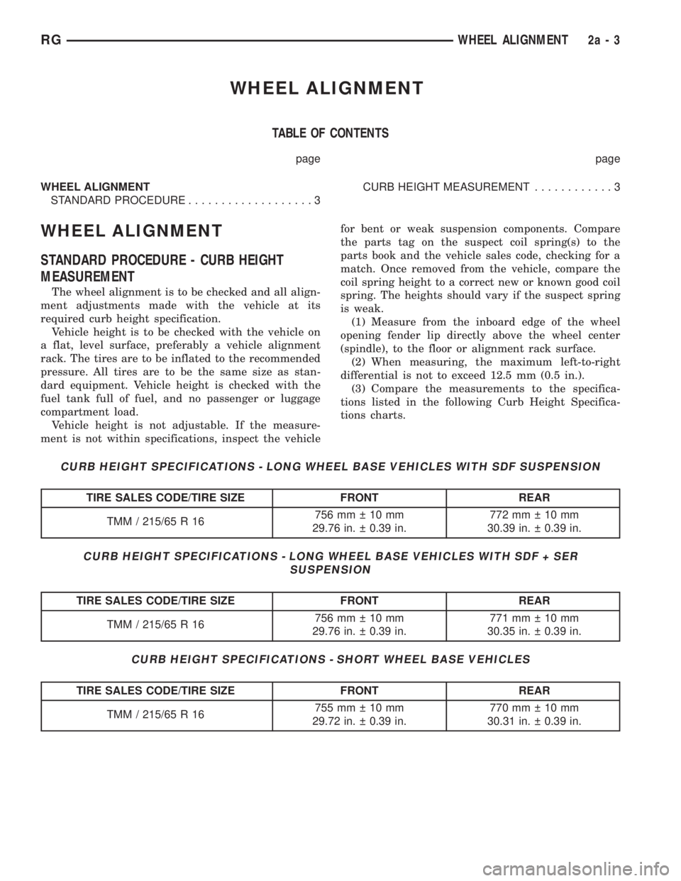
tions listed in the following Curb Height Specifica-
tions charts.
CURB HEIGHT SPECIFICATIONS - LONG WHEEL BASE VEHICLES WITH SDF SUSPENSION
TIRE SALES CODE/TIRE SIZE FRONT REAR
TMM / 215/65 R 16756mm 10mm
29.76 in. 0.39 in.772mm 10mm
30.39 in. 0.39 in.
CURB HEIGHT SPECIFICATIONS - LONG WHEEL BASE VEHICLES WITH SDF + SER
SUSPENSION
TIRE SALES CODE/TIRE SIZE FRONT REAR
TMM / 215/65 R 16756mm 10mm
29.76 in. 0.39 in.771mm 10mm
30.35 in. 0.39 in.
CURB HEIGHT SPECIFICATIONS - SHORT WHEEL BASE VEHICLES
TIRE SALES CODE/TIRE SIZE FRONT REAR
TMM / 215/65 R 16755mm 10mm
29.72 in. 0.39 in.770mm 10mm
30.31 in. 0.39 in.
RGWHEEL ALIGNMENT2a-3
Page 1621 of 4284
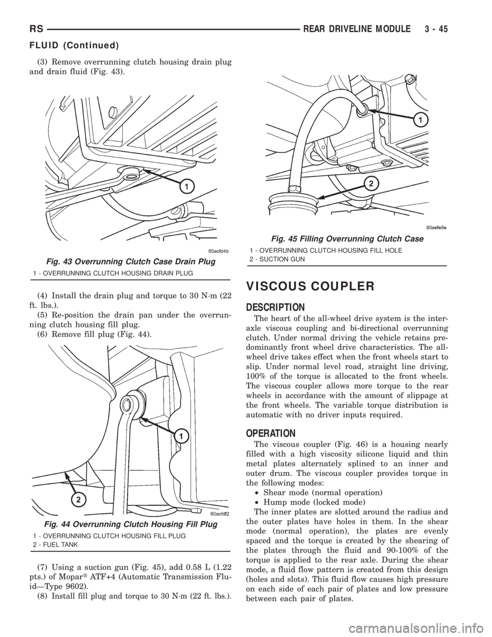
(3) Remove overrunning clutch housing drain plug
and drain fluid (Fig. 43).
(4) Install the drain plug and torque to 30 N´m (22
ft. lbs.).
(5) Re-position the drain pan under the overrun-
ning clutch housing fill plug.
(6) Remove fill plug (Fig. 44).
(7) Using a suction gun (Fig. 45), add 0.58 L (1.22
pts.) of MopartATF+4 (Automatic Transmission Flu-
idÐType 9602).
(8)
Install fill plug and torque to 30 N´m (22 ft. lbs.).
VISCOUS COUPLER
DESCRIPTION
The heart of the all-wheel drive system is the inter-
axle viscous coupling and bi-directional overrunning
clutch. Under normal driving the vehicle retains pre-
dominantly front wheel drive characteristics. The all-
wheel drive takes effect when the front wheels start to
slip. Under normal level road, straight line driving,
100% of the torque is allocated to the front wheels.
The viscous coupler allows more torque to the rear
wheels in accordance with the amount of slippage at
the front wheels. The variable torque distribution is
automatic with no driver inputs required.
OPERATION
The viscous coupler (Fig. 46) is a housing nearly
filled with a high viscosity silicone liquid and thin
metal plates alternately splined to an inner and
outer drum. The viscous coupler provides torque in
the following modes:
²Shear mode (normal operation)
²Hump mode (locked mode)
The inner plates are slotted around the radius and
the outer plates have holes in them. In the shear
mode (normal operation), the plates are evenly
spaced and the torque is created by the shearing of
the plates through the fluid and 90-100% of the
torque is applied to the rear axle. During the shear
mode, a fluid flow pattern is created from this design
(holes and slots). This fluid flow causes high pressure
on each side of each pair of plates and low pressure
between each pair of plates.
Fig. 43 Overrunning Clutch Case Drain Plug
1 - OVERRUNNING CLUTCH HOUSING DRAIN PLUG
Fig. 44 Overrunning Clutch Housing Fill Plug
1 - OVERRUNNING CLUTCH HOUSING FILL PLUG
2 - FUEL TANK
Fig. 45 Filling Overrunning Clutch Case
1 - OVERRUNNING CLUTCH HOUSING FILL HOLE
2 - SUCTION GUN
RSREAR DRIVELINE MODULE3-45
FLUID (Continued)
Page 1755 of 4284
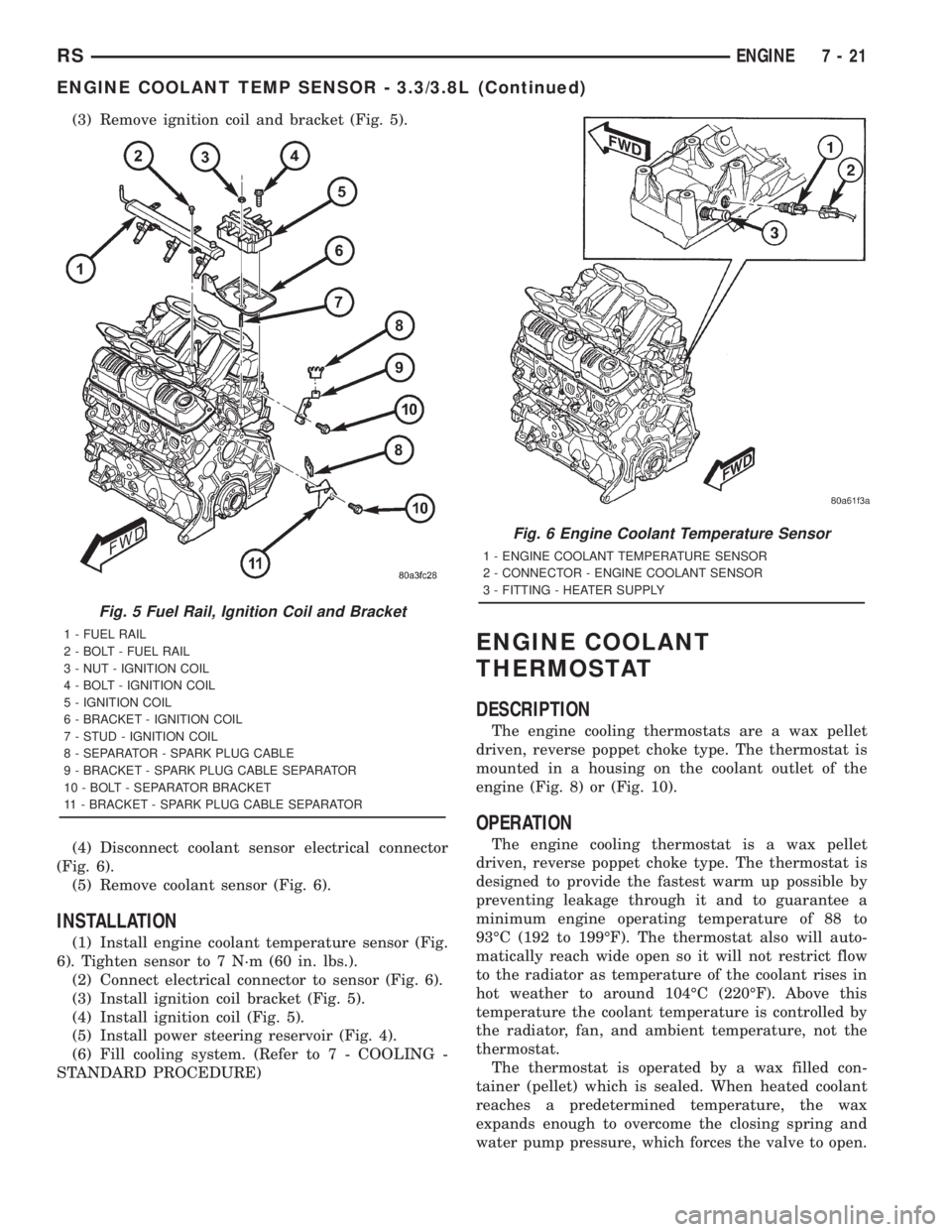
(3) Remove ignition coil and bracket (Fig. 5).
(4) Disconnect coolant sensor electrical connector
(Fig. 6).
(5) Remove coolant sensor (Fig. 6).
INSTALLATION
(1) Install engine coolant temperature sensor (Fig.
6). Tighten sensor to 7 N´m (60 in. lbs.).
(2) Connect electrical connector to sensor (Fig. 6).
(3) Install ignition coil bracket (Fig. 5).
(4) Install ignition coil (Fig. 5).
(5) Install power steering reservoir (Fig. 4).
(6) Fill cooling system. (Refer to 7 - COOLING -
STANDARD PROCEDURE)
ENGINE COOLANT
THERMOSTAT
DESCRIPTION
The engine cooling thermostats are a wax pellet
driven, reverse poppet choke type. The thermostat is
mounted in a housing on the coolant outlet of the
engine (Fig. 8) or (Fig. 10).
OPERATION
The engine cooling thermostat is a wax pellet
driven, reverse poppet choke type. The thermostat is
designed to provide the fastest warm up possible by
preventing leakage through it and to guarantee a
minimum engine operating temperature of 88 to
93ÉC (192 to 199ÉF). The thermostat also will auto-
matically reach wide open so it will not restrict flow
to the radiator as temperature of the coolant rises in
hot weather to around 104ÉC (220ÉF). Above this
temperature the coolant temperature is controlled by
the radiator, fan, and ambient temperature, not the
thermostat.
The thermostat is operated by a wax filled con-
tainer (pellet) which is sealed. When heated coolant
reaches a predetermined temperature, the wax
expands enough to overcome the closing spring and
water pump pressure, which forces the valve to open.
Fig. 5 Fuel Rail, Ignition Coil and Bracket
1 - FUEL RAIL
2 - BOLT - FUEL RAIL
3 - NUT - IGNITION COIL
4 - BOLT - IGNITION COIL
5 - IGNITION COIL
6 - BRACKET - IGNITION COIL
7 - STUD - IGNITION COIL
8 - SEPARATOR - SPARK PLUG CABLE
9 - BRACKET - SPARK PLUG CABLE SEPARATOR
10 - BOLT - SEPARATOR BRACKET
11 - BRACKET - SPARK PLUG CABLE SEPARATOR
Fig. 6 Engine Coolant Temperature Sensor
1 - ENGINE COOLANT TEMPERATURE SENSOR
2 - CONNECTOR - ENGINE COOLANT SENSOR
3 - FITTING - HEATER SUPPLY
RSENGINE7-21
ENGINE COOLANT TEMP SENSOR - 3.3/3.8L (Continued)
Page 1821 of 4284
²Engine running at 420 to 480 rpm for 10 sec-
onds
²Oil pressure switch closed to ground for (1 sec-
ond minimum, 2 seconds maximum)
Chime rate: 168 to 192 chimes per minute.
DIAGNOSIS AND TESTING - SEAT BELT CHIME
The seat belt chime will sound for 4 to 8 seconds,
when the ignition is turned on and the driver's seat
belt is not buckled (seat belt switch is closed to
ground). This is a reminder to the driver to buckle
the seat belt. The seat belt lamp is controlled by the
ORC. The cluster will also bulb check the seat belt
warning lamp for 6 seconds. Buckling the driver's
seat belt before the time out has expired will cause
the chime to stop immediately. Chime rate: 38 to 62
chimes per minute but the lamp will remain on until
6 seconds have expired.
To test the seat belt warning system, the ignition
switch must be in the OFF position for 1 minute
before starting the test. Turn the ignition switch to
the on position with the driver's seat belt not buck-
led. The seat belt warning lamp should light and the
chime should sound 4 to 8 seconds.
DIAGNOSIS AND TESTING - SEAT BELT LAMP
The seat belt lamp in the instrument cluster sig-
nals the vehicle passengers to fasten their seat belts.
The seat belt lamp is illuminated directly by the
instrument cluster for 6 seconds after the instrument
cluster receives the message from the ORC. The seat
belt lamp is therefore illuminated for 6 seconds
whenever the ignition switch is moved to run/start
position.
(1) While ignition is off, the seat belt lamp will not
be illuminated.
(2) The ignition power feed status will be updated
every 250 milliseconds or on change.
(3) This lamp will be checked by the instrument
cluster for 6 seconds with every run/start cycle of the
ignition switch.
DIAGNOSIS AND TESTING - TURN SIGNAL ON
CHIME
The turn signal on chime will warn the driver that
the turn signals have been left on. When the body
control module receives a turn signal input for 1/4.0
mile, vehicle speed is greater than 24 km/h (15 mph),
the chime will sound continuously until the turn sig-nal is turned OFF. If vehicle speed drops below 24
km/h (15 mph) prior to the warning being activated,
the accumulated distance traveled will be reset. The
turn signal chime is not activated when the emer-
gency flashers are turned on. Chime rate: 50612
chimes per minute.
For the turn signal warning system to operate:
²Must have input from either the right or left
turn signal lamps. Creates a voltage change between
0 and battery voltage.
²The vehicle speed sensor sends a message to the
Powertrain Control Module that vehicle has exceeded
24 km/h (15 mph) for 1/4.0 mile).
²When the above two conditions are met, the
chime will sound. The chime will stop when no fur-
ther voltage change is detected.
²If hazard warning signals are pulsing, no chime
will sound.
²If speed drops below 24 km/h (15 mph) before
the warning is issued, the warning will not be issued
and the distance counter will be reset.
²If turn signal lamps are not working properly,
the chime will not sound.
²When using the scan tool, refer to the proper
Body Diagnostic Manual for the procedure.
DIAGNOSIS AND TESTING - WARNING LAMP
ANNOUNCEMENT CHIME
The warning lamp announcement chime will warn
the driver to scan the instrument cluster to observe
which warning lamp is illuminated. Whenever the
volts, low fuel, airbag, door ajar or gate ajar lamps
are first illuminated, the chime will sound one tone.
The door/liftgate ajar warning lamp announcement
chime sounds only if the vehicle speed is above 4
m.p.h.
Two seconds after ignition switch is turned ON or
until the seat belt warning chime ends, all warning
announcement chimes will be consolidated into one
warning announcement. This will occur 2 seconds
after the seat belt warning chime ends. If a warning
announcement should occur while another warning
chime in progress (turn signal, low oil pressure or
high speed warnings), no additional chimes will
sound after the chime in progress ends. All associ-
ated lamps will be illuminated, and the active chime
will be the warning announcement.
RSCHIME/BUZZER8B-3
CHIME/BUZZER (Continued)
Page 1833 of 4284
²Throttle Position Sensor
²Torque Management Input (From TCM)
²Transaxle Control Module (TCM)
²Transaxle Gear Engagement (From TCM)
²Vehicle Speed (from transmission control mod-
ule)
NOTE: PCM Outputs:
²Air Conditioning Clutch Relay
²Automatic Shut Down (ASD) and Fuel Pump
Relays
²Data Link Connector (PCI and SCI Transmit)
²Double Start Override
²EGR Solenoid
²Fuel Injectors
²Generator Field
²High Speed Fan Relay
²Idle Air Control Motor
²Ignition Coils
²Leak Detection Pump
²Low Speed Fan Relay
²MTV Actuator
²Proportional Purge Solenoid
²SRV Valve
²Speed Control Relay
²Speed Control Vent Relay
²Speed Control Vacuum Relay
²8 Volt Output
²5 Volt Output
Based on inputs it receives, the powertrain control
module (PCM) adjusts fuel injector pulse width, idle
speed, ignition timing, and canister purge operation.
The PCM regulates the cooling fans, air conditioning
and speed control systems. The PCM changes gener-
ator charge rate by adjusting the generator field.
The PCM adjusts injector pulse width (air-fuel
ratio) based on the following inputs.
²Battery Voltage
²Intake Air Temperature Sensor
²Engine Coolant Temperature
²Engine Speed (crankshaft position sensor)
²Exhaust Gas Oxygen Content (heated oxygen
sensors)
²Manifold Absolute Pressure
²Throttle Position
The PCM adjusts engine idle speed through the
idle air control motor based on the following inputs.
²Brake Switch
²Engine Coolant Temperature
²Engine Speed (crankshaft position sensor)
²Park/Neutral (transmission gear selection)
²Transaxle Gear Engagement
²Throttle Position
²Vehicle Speed (from Transmission Control Mod-
ule)The PCM adjusts ignition timing based on the fol-
lowing inputs.
²Intake Air Temperature
²Engine Coolant Temperature
²Engine Speed (crankshaft position sensor)
²Knock Sensor
²Manifold Absolute Pressure
²Park/Neutral (transmission gear selection)
²Transaxle Gear Engagement
²Throttle Position
The automatic shut down (ASD) and fuel pump
relays are mounted externally, but turned on and off
by the powertrain control module through the same
circuit.
The camshaft and crankshaft signals are sent to
the powertrain control module. If the PCM does not
receive both signals within approximately one second
of engine cranking, it deactivates the ASD and fuel
pump relays. When these relays are deactivated,
power is shut off to the fuel injectors, ignition coils,
fuel pump and the heating element in each oxygen
sensor.
The PCM contains a voltage converter that
changes battery voltage to a regulated 8.0 volts. The
8.0 volts power the camshaft position sensor, crank-
shaft position sensor and vehicle speed sensor. The
PCM also provides a 5.0 volts supply for the engine
coolant temperature sensor, intake air temperature
sensor, manifold absolute pressure sensor and throt-
tle position sensor.
The PCM engine control strategy prevents reduced
idle speeds until after the engine operates for 320 km
(200 miles). If the PCM is replaced after 320 km (200
miles) of usage, update the mileage in new PCM. Use
the DRB scan tool to change the mileage in the PCM.
Refer to the appropriate Powertrain Diagnostic Man-
ual and the DRB scan tool.
DIAGNOSTIC TROUBLE CODE
DESCRIPTION
A Diagnostic Trouble Code (DTC) indicates the
PCM has recognized an abnormal condition in the
system.
Remember that DTC's are the results of a sys-
tem or circuit failure, but do not directly iden-
tify the failed component or components.
NOTE: For a list of DTC's, refer to the charts in this
section.
RSELECTRONIC CONTROL MODULES8E-9
POWERTRAIN CONTROL MODULE (Continued)
Page 1834 of 4284
(M) Check Engine Lamp (MIL) will illuminate during engine operation if this Diagnostic Trouble Code was recorded.
(G) Generator Lamp Illuminated
GENERIC SCAN
TOOL CODEDRB SCAN TOOL DISPLAY DESCRIPTION OF DIAGNOSTIC TROUBLE CODE
P0071 Ambient Temp Sensor Preformance Ambient change less than 3É C in 200 Miles
P0106 (M) Barometric Pressure Out of Range MAP sensor input voltage out of an acceptable range
detected during reading of barometric pressure at key-on.
P0107 (M) Map Sensor Voltage Too Low MAP sensor input below minimum acceptable voltage.
P0108 (M) Map Sensor Voltage Too High MAP sensor input above maximum acceptable voltage.
P0111 (M) Intake Air Temp Sensor Preformance Intake Air change less than 3É C in 200 Miles
P0112 (M) Intake Air Temp Sensor Voltage Low Intake air (charge) temperature sensor input below the
minimum acceptable voltage.
P0113 (M) Intake Air Temp Sensor Voltage High Intake air (charge) temperature sensor input above the
maximum acceptable voltage.
P0116 Engine Coolant Temp Performance A rationatilty error has been detected in the coolant temp
sensor.
P0117 (M) ECT Sensor Voltage Too Low Engine coolant temperature sensor input below the minimum
acceptable voltage.
P0118 (M) ECT Sensor Voltage Too High Engine coolant temperature sensor input above the
maximum acceptable voltage.
P0121 (M) TPS Voltage Does Not Agree With
MAPTPS signal does not correlate to MAP sensor signal.
P0122 (M) Throttle Position Sensor Voltage
LowThrottle position sensor input below the acceptable voltage
range.
P0123 (M) Throttle Position Sensor Voltage
HighThrottle position sensor input above the maximum
acceptable voltage.
P0125 (M) Engine Coolant Temp Not Reached Time to enter Closed Loop Operation (Fuel Control) is
excessive.
P0130 1/1 O2 Sensor Heater Relay Circuit An open or shorted condition detected in the ASD or CNG
shutoff relay control ckt.
P0131 (M) 1/1 O2 Sensor Shorted To Ground Oxygen sensor input voltage maintained below normal
operating range.
P0132 (M) 1/1 O2 Sensor Shorted To Voltage Oxygen sensor input voltage maintained above normal
operating range.
P0133 (M) 1/1 O2 Sensor Slow Response Oxygen sensor response slower than minimum required
switching frequency.
P0134 (M) 1/1 O2 Sensor Stays at Center Neither rich or lean condition is detected from the oxygen
sensor input.
P0135 (M) 1/1 O2 Sensor Heater Failure Oxygen sensor heater element malfunction.
P0136 1/2 O2 Sensor Heater Relay Circuit An open or shorted condition detected in the ASD or CNG
shutoff relay control ckt.
P0137 (M) 1/2 O2 Sensor Shorted To Ground Oxygen sensor input voltage maintained below normal
operating range.
P0138 (M) 1/2 O2 Sensor Shorted To Voltage Oxygen sensor input voltage maintained above normal
operating range.
P0139 (M) 1/2 O2 Sensor Slow Response Oxygen sensor response not as expected.
8E - 10 ELECTRONIC CONTROL MODULESRS
POWERTRAIN CONTROL MODULE (Continued)