2001 CHRYSLER VOYAGER engine coolant
[x] Cancel search: engine coolantPage 1020 of 4284
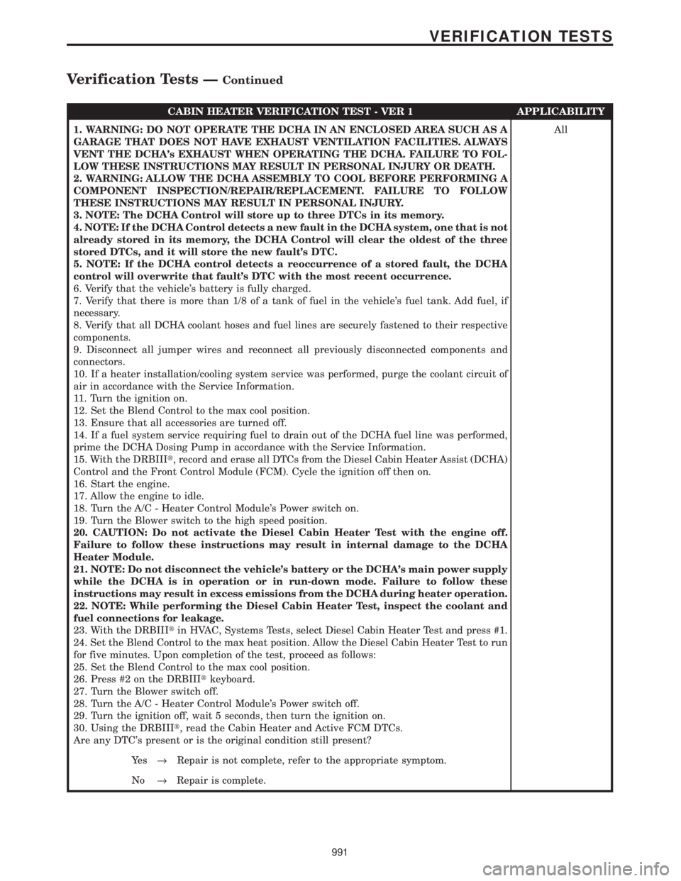
CABIN HEATER VERIFICATION TEST - VER 1 APPLICABILITY
1. WARNING: DO NOT OPERATE THE DCHA IN AN ENCLOSED AREA SUCH AS A
GARAGE THAT DOES NOT HAVE EXHAUST VENTILATION FACILITIES. ALWAYS
VENT THE DCHA's EXHAUST WHEN OPERATING THE DCHA. FAILURE TO FOL-
LOW THESE INSTRUCTIONS MAY RESULT IN PERSONAL INJURY OR DEATH.
2. WARNING: ALLOW THE DCHA ASSEMBLY TO COOL BEFORE PERFORMING A
COMPONENT INSPECTION/REPAIR/REPLACEMENT. FAILURE TO FOLLOW
THESE INSTRUCTIONS MAY RESULT IN PERSONAL INJURY.
3. NOTE: The DCHA Control will store up to three DTCs in its memory.
4. NOTE: If the DCHA Control detects a new fault in the DCHA system, one that is not
already stored in its memory, the DCHA Control will clear the oldest of the three
stored DTCs, and it will store the new fault's DTC.
5. NOTE: If the DCHA control detects a reoccurrence of a stored fault, the DCHA
control will overwrite that fault's DTC with the most recent occurrence.
6. Verify that the vehicle's battery is fully charged.
7. Verify that there is more than 1/8 of a tank of fuel in the vehicle's fuel tank. Add fuel, if
necessary.
8. Verify that all DCHA coolant hoses and fuel lines are securely fastened to their respective
components.
9. Disconnect all jumper wires and reconnect all previously disconnected components and
connectors.
10. If a heater installation/cooling system service was performed, purge the coolant circuit of
air in accordance with the Service Information.
11. Turn the ignition on.
12. Set the Blend Control to the max cool position.
13. Ensure that all accessories are turned off.
14. If a fuel system service requiring fuel to drain out of the DCHA fuel line was performed,
prime the DCHA Dosing Pump in accordance with the Service Information.
15. With the DRBIIIt, record and erase all DTCs from the Diesel Cabin Heater Assist (DCHA)
Control and the Front Control Module (FCM). Cycle the ignition off then on.
16. Start the engine.
17. Allow the engine to idle.
18. Turn the A/C - Heater Control Module's Power switch on.
19. Turn the Blower switch to the high speed position.
20. CAUTION: Do not activate the Diesel Cabin Heater Test with the engine off.
Failure to follow these instructions may result in internal damage to the DCHA
Heater Module.
21. NOTE: Do not disconnect the vehicle's battery or the DCHA's main power supply
while the DCHA is in operation or in run-down mode. Failure to follow these
instructions may result in excess emissions from the DCHA during heater operation.
22. NOTE: While performing the Diesel Cabin Heater Test, inspect the coolant and
fuel connections for leakage.
23. With the DRBIIItin HVAC, Systems Tests, select Diesel Cabin Heater Test and press #1.
24. Set the Blend Control to the max heat position. Allow the Diesel Cabin Heater Test to run
for five minutes. Upon completion of the test, proceed as follows:
25. Set the Blend Control to the max cool position.
26. Press #2 on the DRBIIItkeyboard.
27. Turn the Blower switch off.
28. Turn the A/C - Heater Control Module's Power switch off.
29. Turn the ignition off, wait 5 seconds, then turn the ignition on.
30. Using the DRBIIIt, read the Cabin Heater and Active FCM DTCs.
Are any DTC's present or is the original condition still present?All
Ye s®Repair is not complete, refer to the appropriate symptom.
No®Repair is complete.
991
VERIFICATION TESTS
Verification Tests ÐContinued
Page 1068 of 4284
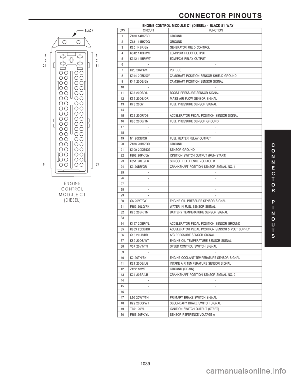
ENGINE CONTROL MODULE C1 (DIESEL) - BLACK 81 WAYCAV CIRCUIT FUNCTION
1 Z130 14BK/BR GROUND
2 Z131 14BK/DG GROUND
3 K20 14BR/GY GENERATOR FIELD CONTROL
4 K342 14BR/WT ECM/PCM RELAY OUTPUT
5 K342 14BR/WT ECM/PCM RELAY OUTPUT
6- -
7 D25 20WT/VT PCI BUS
8 K944 20BK/GY CAMSHAFT POSITION SENSOR SHIELD GROUND
9 K44 20DB/GY CAMSHAFT POSITION SENSOR SIGNAL
10 - -
11 K37 20DB/YL BOOST PRESSURE SENSOR SIGNAL
12 K55 20DB/OR MASS AIR FLOW SENSOR SIGNAL
13 K78 20GY FUEL PRESSURE SENSOR SIGNAL
14 - -
15 K22 20OR/DB ACCELERATOR PEDAL POSITION SENSOR SIGNAL
16 K80 20DB/TN FUEL PRESSURE SENSOR GROUND
17 - -
18 - -
19 N1 20DB/OR FUEL HEATER RELAY OUTPUT
20 Z138 20BK/OR GROUND
21 K900 20DB/DG SENSOR GROUND
22 F202 20PK/GY IGNITION SWITCH OUTPUT (RUN-START)
23 F851 20LB/PK SENSOR REFERENCE VOLTAGE B
24 K3 20BR/OR CRANKSHAFT POSITION SENSOR SIGNAL NO. 1
25 - -
26 - -
27 - -
28 - -
29 - -
30 G6 20VT/GY ENGINE OIL PRESSURE SENSOR SIGNAL
31 F853 20LG/PK WATER IN FUEL SENSOR SIGNAL
32 K25 20BR/TN BATTERY TEMPERATURE SENSOR SIGNAL
33 - -
34 K167 20BR/YL ACCELERATOR PEDAL POSITION SENSOR GROUND
35 K853 20DB/BR ACCELERATOR PEDAL POSITION SENSOR 5 VOLT SUPPLY
36 C18 20LB/BR A/C PRESSURE SENSOR SIGNAL
37 K89 20DB/WT ENGINE OIL TEMPERATURE SENSOR SIGNAL
38 V37 20VT/TN SPEED CONTROL SWITCH SIGNAL
39 - -
40 K2 20TN/BK ENGINE COOLANT TEMPERATURE SENSOR SIGNAL
41 K21 20DB/LG INTAKE AIR TEMPERATURE SENSOR SIGNAL
42 Z122 18WT GROUND (DRAIN)
43 K24 20BR/LB CRANKSHAFT POSITION SENSOR SIGNAL NO. 2
44 - -
45 - -
46 - -
47 L50 20WT/TN PRIMARY BRAKE SWITCH SIGNAL
48 B29 20DG/WT SECONDARY BRAKE SWITCH SIGNAL
49 T751 20YL IGNITION SWITCH OUTPUT (START)
50 F855 20PK/YL SENSOR REFERENCE VOLTAGE A
C
O
N
N
E
C
T
O
R
P
I
N
O
U
T
S
1039
CONNECTOR PINOUTS
Page 1100 of 4284
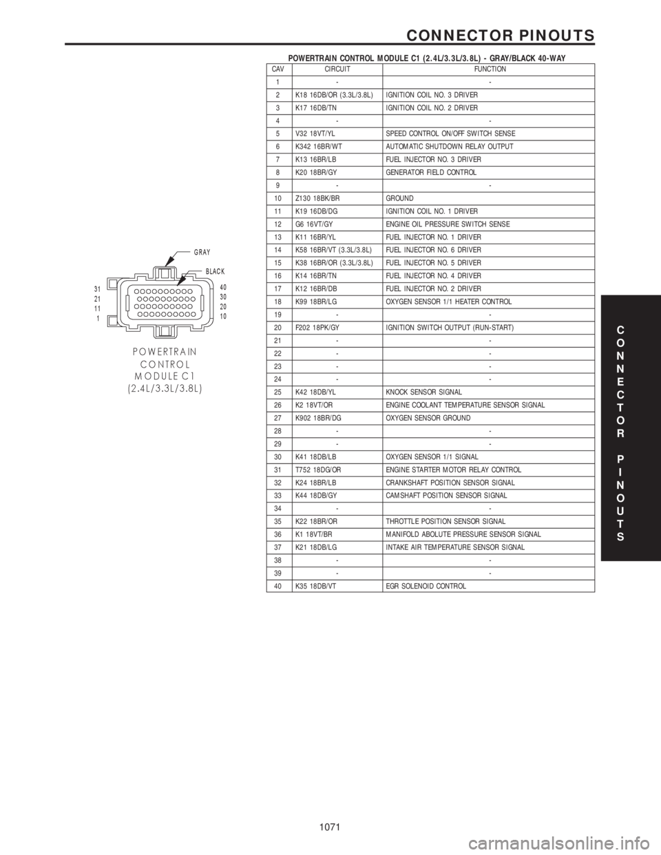
POWERTRAIN CONTROL MODULE C1 (2.4L/3.3L/3.8L) - GRAY/BLACK 40-WAYCAV CIRCUIT FUNCTION
1- -
2 K18 16DB/OR (3.3L/3.8L) IGNITION COIL NO. 3 DRIVER
3 K17 16DB/TN IGNITION COIL NO. 2 DRIVER
4- -
5 V32 18VT/YL SPEED CONTROL ON/OFF SWITCH SENSE
6 K342 16BR/WT AUTOMATIC SHUTDOWN RELAY OUTPUT
7 K13 16BR/LB FUEL INJECTOR NO. 3 DRIVER
8 K20 18BR/GY GENERATOR FIELD CONTROL
9- -
10 Z130 18BK/BR GROUND
11 K19 16DB/DG IGNITION COIL NO. 1 DRIVER
12 G6 16VT/GY ENGINE OIL PRESSURE SWITCH SENSE
13 K11 16BR/YL FUEL INJECTOR NO. 1 DRIVER
14 K58 16BR/VT (3.3L/3.8L) FUEL INJECTOR NO. 6 DRIVER
15 K38 16BR/OR (3.3L/3.8L) FUEL INJECTOR NO. 5 DRIVER
16 K14 16BR/TN FUEL INJECTOR NO. 4 DRIVER
17 K12 16BR/DB FUEL INJECTOR NO. 2 DRIVER
18 K99 18BR/LG OXYGEN SENSOR 1/1 HEATER CONTROL
19 - -
20 F202 18PK/GY IGNITION SWITCH OUTPUT (RUN-START)
21 - -
22 - -
23 - -
24 - -
25 K42 18DB/YL KNOCK SENSOR SIGNAL
26 K2 18VT/OR ENGINE COOLANT TEMPERATURE SENSOR SIGNAL
27 K902 18BR/DG OXYGEN SENSOR GROUND
28 - -
29 - -
30 K41 18DB/LB OXYGEN SENSOR 1/1 SIGNAL
31 T752 18DG/OR ENGINE STARTER MOTOR RELAY CONTROL
32 K24 18BR/LB CRANKSHAFT POSITION SENSOR SIGNAL
33 K44 18DB/GY CAMSHAFT POSITION SENSOR SIGNAL
34 - -
35 K22 18BR/OR THROTTLE POSITION SENSOR SIGNAL
36 K1 18VT/BR MANIFOLD ABOLUTE PRESSURE SENSOR SIGNAL
37 K21 18DB/LG INTAKE AIR TEMPERATURE SENSOR SIGNAL
38 - -
39 - -
40 K35 18DB/VT EGR SOLENOID CONTROL
C
O
N
N
E
C
T
O
R
P
I
N
O
U
T
S
1071
CONNECTOR PINOUTS
Page 1215 of 4284
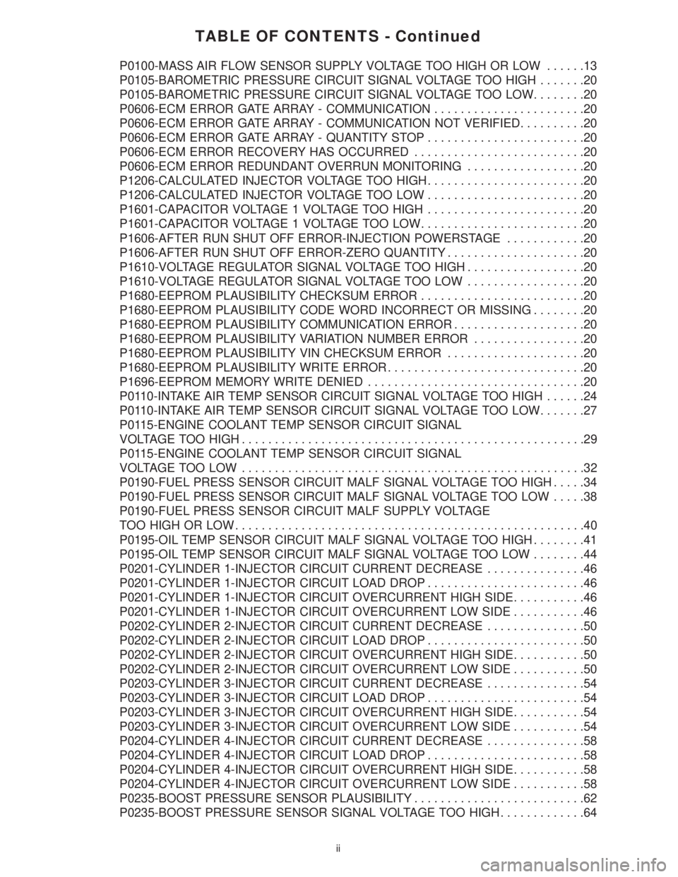
TABLE OF CONTENTS - Continued
P0100-MASS AIR FLOW SENSOR SUPPLY VOLTAGE TOO HIGH OR LOW......13
P0105-BAROMETRIC PRESSURE CIRCUIT SIGNAL VOLTAGE TOO HIGH.......20
P0105-BAROMETRIC PRESSURE CIRCUIT SIGNAL VOLTAGE TOO LOW........20
P0606-ECM ERROR GATE ARRAY - COMMUNICATION.......................20
P0606-ECM ERROR GATE ARRAY - COMMUNICATION NOT VERIFIED..........20
P0606-ECM ERROR GATE ARRAY - QUANTITY STOP........................20
P0606-ECM ERROR RECOVERY HAS OCCURRED..........................20
P0606-ECM ERROR REDUNDANT OVERRUN MONITORING..................20
P1206-CALCULATED INJECTOR VOLTAGE TOO HIGH........................20
P1206-CALCULATED INJECTOR VOLTAGE TOO LOW........................20
P1601-CAPACITOR VOLTAGE 1 VOLTAGE TOO HIGH........................20
P1601-CAPACITOR VOLTAGE 1 VOLTAGE TOO LOW.........................20
P1606-AFTER RUN SHUT OFF ERROR-INJECTION POWERSTAGE............20
P1606-AFTER RUN SHUT OFF ERROR-ZERO QUANTITY.....................20
P1610-VOLTAGE REGULATOR SIGNAL VOLTAGE TOO HIGH..................20
P1610-VOLTAGE REGULATOR SIGNAL VOLTAGE TOO LOW..................20
P1680-EEPROM PLAUSIBILITY CHECKSUM ERROR.........................20
P1680-EEPROM PLAUSIBILITY CODE WORD INCORRECT OR MISSING........20
P1680-EEPROM PLAUSIBILITY COMMUNICATION ERROR....................20
P1680-EEPROM PLAUSIBILITY VARIATION NUMBER ERROR.................20
P1680-EEPROM PLAUSIBILITY VIN CHECKSUM ERROR.....................20
P1680-EEPROM PLAUSIBILITY WRITE ERROR..............................20
P1696-EEPROM MEMORY WRITE DENIED.................................20
P0110-INTAKE AIR TEMP SENSOR CIRCUIT SIGNAL VOLTAGE TOO HIGH......24
P0110-INTAKE AIR TEMP SENSOR CIRCUIT SIGNAL VOLTAGE TOO LOW.......27
P0115-ENGINE COOLANT TEMP SENSOR CIRCUIT SIGNAL
VOLTAGE TOO HIGH....................................................29
P0115-ENGINE COOLANT TEMP SENSOR CIRCUIT SIGNAL
VOLTAGETOO LOW ....................................................32
P0190-FUEL PRESS SENSOR CIRCUIT MALF SIGNAL VOLTAGE TOO HIGH.....34
P0190-FUEL PRESS SENSOR CIRCUIT MALF SIGNAL VOLTAGE TOO LOW.....38
P0190-FUEL PRESS SENSOR CIRCUIT MALF SUPPLY VOLTAGE
TOO HIGH OR LOW.....................................................40
P0195-OIL TEMP SENSOR CIRCUIT MALF SIGNAL VOLTAGE TOO HIGH........41
P0195-OIL TEMP SENSOR CIRCUIT MALF SIGNAL VOLTAGE TOO LOW........44
P0201-CYLINDER 1-INJECTOR CIRCUIT CURRENT DECREASE...............46
P0201-CYLINDER 1-INJECTOR CIRCUIT LOAD DROP........................46
P0201-CYLINDER 1-INJECTOR CIRCUIT OVERCURRENT HIGH SIDE...........46
P0201-CYLINDER 1-INJECTOR CIRCUIT OVERCURRENT LOW SIDE...........46
P0202-CYLINDER 2-INJECTOR CIRCUIT CURRENT DECREASE...............50
P0202-CYLINDER 2-INJECTOR CIRCUIT LOAD DROP........................50
P0202-CYLINDER 2-INJECTOR CIRCUIT OVERCURRENT HIGH SIDE...........50
P0202-CYLINDER 2-INJECTOR CIRCUIT OVERCURRENT LOW SIDE...........50
P0203-CYLINDER 3-INJECTOR CIRCUIT CURRENT DECREASE...............54
P0203-CYLINDER 3-INJECTOR CIRCUIT LOAD DROP........................54
P0203-CYLINDER 3-INJECTOR CIRCUIT OVERCURRENT HIGH SIDE...........54
P0203-CYLINDER 3-INJECTOR CIRCUIT OVERCURRENT LOW SIDE...........54
P0204-CYLINDER 4-INJECTOR CIRCUIT CURRENT DECREASE...............58
P0204-CYLINDER 4-INJECTOR CIRCUIT LOAD DROP........................58
P0204-CYLINDER 4-INJECTOR CIRCUIT OVERCURRENT HIGH SIDE...........58
P0204-CYLINDER 4-INJECTOR CIRCUIT OVERCURRENT LOW SIDE...........58
P0235-BOOST PRESSURE SENSOR PLAUSIBILITY..........................62
P0235-BOOST PRESSURE SENSOR SIGNAL VOLTAGE TOO HIGH.............64
ii
Page 1217 of 4284
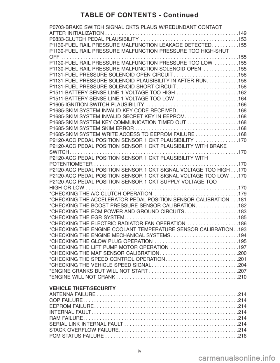
TABLE OF CONTENTS - Continued
P0703-BRAKE SWITCH SIGNAL CKTS PLAUS W/REDUNDANT CONTACT
AFTER INITIALIZATION.................................................149
P0833-CLUTCH PEDAL PLAUSIBILITY....................................153
P1130-FUEL RAIL PRESSURE MALFUNCTION LEAKAGE DETECTED..........155
P1130-FUEL RAIL PRESSURE MALFUNCTION PRESSURE TOO HIGH-SHUT
OFF .................................................................155
P1130-FUEL RAIL PRESSURE MALFUNCTION PRESSURE TOO LOW.........155
P1130-FUEL RAIL PRESSURE MALFUNCTION SOLENOID OPEN.............155
P1131-FUEL PRESSURE SOLENOID OPEN CIRCUIT........................158
P1131-FUEL PRESSURE SOLENOID PLAUSIBILITY IN AFTER-RUN............158
P1131-FUEL PRESSURE SOLENOID SHORT CIRCUIT.......................158
P1511-BATTERY SENSE LINE 1 VOLTAGE TOO HIGH.......................162
P1511-BATTERY SENSE LINE 1 VOLTAGE TOO LOW.......................164
P1605-IGNITION SWITCH PLAUSIBILITY..................................166
P1685-SKIM SYSTEM INVALID KEY CODE RECEIVED.......................168
P1685-SKIM SYSTEM INVALID SECRET KEY IN EEPROM....................168
P1685-SKIM SYSTEM KEY COMMUNICATION TIMED OUT...................168
P1685-SKIM SYSTEM SKIM ERROR......................................168
P1685-SKIM SYSTEM WRITE ACCESS TO EEPROM FAILURE................168
P2120-ACC PEDAL POSITION SENSOR 1 CKT PLAUSIBILITY................170
P2120-ACC PEDAL POSITION SENSOR 1 CKT PLAUSIBILITY WITH BRAKE
SWITCH..............................................................170
P2120-ACC PEDAL POSITION SENSOR 1 CKT PLAUSIBILITY WITH
POTENTIOMETER.....................................................170
P2120-ACC PEDAL POSITION SENSOR 1 CKT SIGNAL VOLTAGE TOO HIGH . . .170
P2120-ACC PEDAL POSITION SENSOR 1 CKT SIGNAL VOLTAGE TOO LOW . . .170
P2120-ACC PEDAL POSITION SENSOR 1 CKT SUPPLY VOLTAGE TOO
HIGH OR LOW........................................................170
*CHECKING THE A/C CLUTCH OPERATION...............................179
*CHECKING THE ACCELERATOR PEDAL POSITION SENSOR CALIBRATION . . .181
*CHECKING THE BOOST PRESSURE SENSOR CALIBRATION................182
*CHECKING THE ECM POWER AND GROUND CIRCUITS....................183
*CHECKING THE EGR SYSTEM..........................................185
*CHECKING THE ELECTRIC RADIATOR FAN OPERATION...................186
*CHECKING THE ENGINE COOLANT TEMPERATURE SENSOR CALIBRATION . .193
*CHECKING THE ENGINE MECHANICAL SYSTEMS.........................194
*CHECKING THE GLOW PLUG OPERATION...............................195
*CHECKING THE LIFT PUMP MOTOR OPERATION.........................197
*CHECKING THE MAF SENSOR CALIBRATION.............................200
*CHECKING THE SPEED CONTROL OPERATION...........................201
*CHECKING THE VEHICLE SPEED SIGNAL................................204
*ENGINE CRANKS BUT WILL NOT START.................................207
*ENGINE WILL NOT CRANK.............................................210
VEHICLE THEFT/SECURITY
ANTENNA FAILURE....................................................214
COP FAILURE.........................................................214
EEPROM FAILURE.....................................................214
INTERNAL FAULT......................................................214
RAM FAILURE.........................................................214
SERIAL LINK INTERNAL FAULT..........................................214
STACK OVERFLOW FAILURE............................................214
PCM STATUS FAILURE.................................................216
iv
Page 1218 of 4284
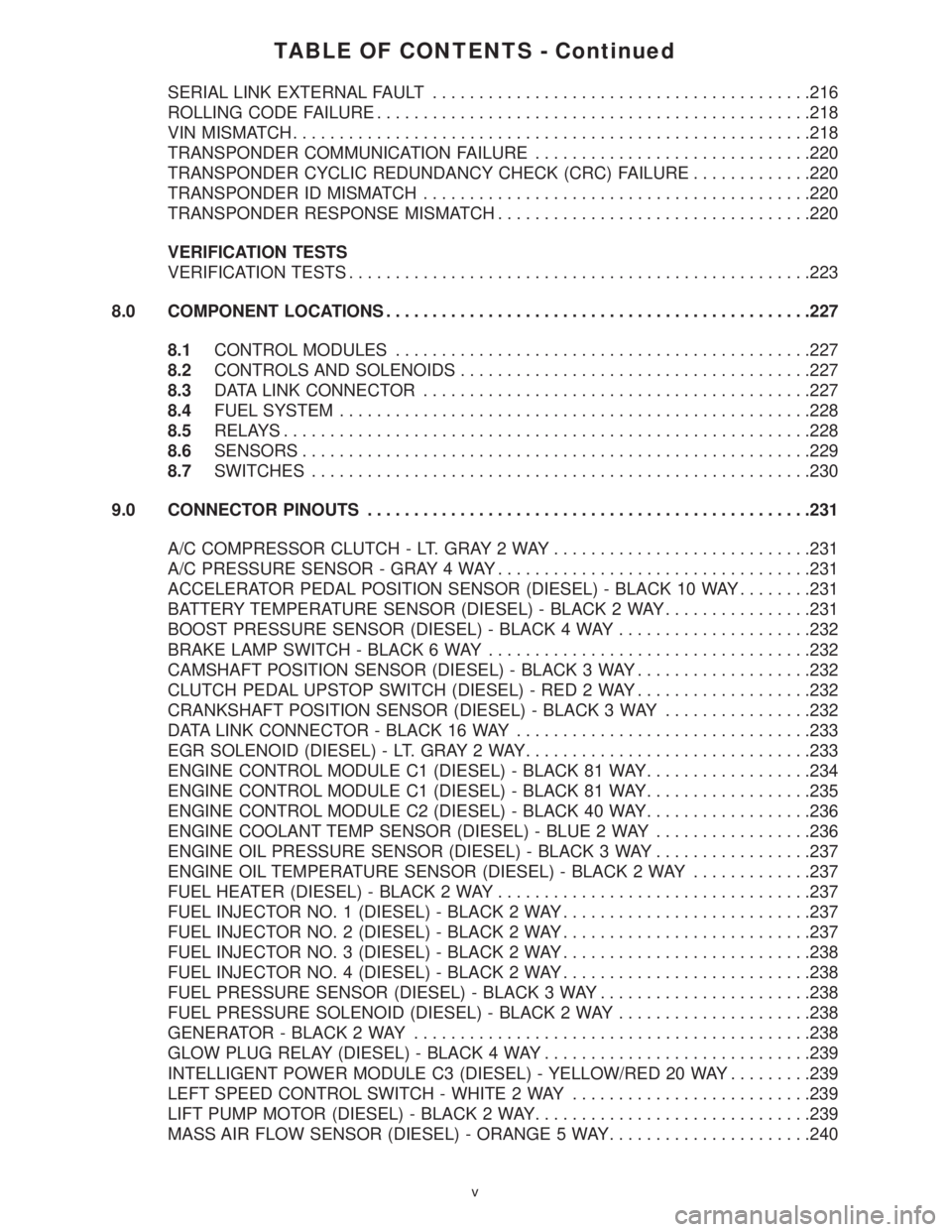
TABLE OF CONTENTS - Continued
SERIAL LINK EXTERNAL FAULT.........................................216
ROLLING CODE FAILURE...............................................218
VIN MISMATCH........................................................218
TRANSPONDER COMMUNICATION FAILURE..............................220
TRANSPONDER CYCLIC REDUNDANCY CHECK (CRC) FAILURE.............220
TRANSPONDER ID MISMATCH..........................................220
TRANSPONDER RESPONSE MISMATCH..................................220
VERIFICATION TESTS
VERIFICATION TESTS..................................................223
8.0 COMPONENT LOCATIONS..............................................227
8.1CONTROL MODULES.............................................227
8.2CONTROLS AND SOLENOIDS......................................227
8.3DATA LINK CONNECTOR..........................................227
8.4FUEL SYSTEM...................................................228
8.5RELAYS.........................................................228
8.6SENSORS.......................................................229
8.7SWITCHES......................................................230
9.0 CONNECTOR PINOUTS................................................231
A/C COMPRESSOR CLUTCH - LT. GRAY 2 WAY............................231
A/C PRESSURE SENSOR - GRAY 4 WAY..................................231
ACCELERATOR PEDAL POSITION SENSOR (DIESEL) - BLACK 10 WAY........231
BATTERY TEMPERATURE SENSOR (DIESEL) - BLACK 2 WAY................231
BOOST PRESSURE SENSOR (DIESEL) - BLACK 4 WAY.....................232
BRAKE LAMP SWITCH - BLACK 6 WAY...................................232
CAMSHAFT POSITION SENSOR (DIESEL) - BLACK 3 WAY...................232
CLUTCH PEDAL UPSTOP SWITCH (DIESEL) - RED 2 WAY...................232
CRANKSHAFT POSITION SENSOR (DIESEL) - BLACK 3 WAY................232
DATA LINK CONNECTOR - BLACK 16 WAY................................233
EGR SOLENOID (DIESEL) - LT. GRAY 2 WAY...............................233
ENGINE CONTROL MODULE C1 (DIESEL) - BLACK 81 WAY..................234
ENGINE CONTROL MODULE C1 (DIESEL) - BLACK 81 WAY..................235
ENGINE CONTROL MODULE C2 (DIESEL) - BLACK 40 WAY..................236
ENGINE COOLANT TEMP SENSOR (DIESEL) - BLUE 2 WAY.................236
ENGINE OIL PRESSURE SENSOR (DIESEL) - BLACK 3 WAY.................237
ENGINE OIL TEMPERATURE SENSOR (DIESEL) - BLACK 2 WAY.............237
FUEL HEATER (DIESEL) - BLACK 2 WAY..................................237
FUEL INJECTOR NO. 1 (DIESEL) - BLACK 2 WAY...........................237
FUEL INJECTOR NO. 2 (DIESEL) - BLACK 2 WAY...........................237
FUEL INJECTOR NO. 3 (DIESEL) - BLACK 2 WAY...........................238
FUEL INJECTOR NO. 4 (DIESEL) - BLACK 2 WAY...........................238
FUEL PRESSURE SENSOR (DIESEL) - BLACK 3 WAY.......................238
FUEL PRESSURE SOLENOID (DIESEL) - BLACK 2 WAY.....................238
GENERATOR - BLACK 2 WAY...........................................238
GLOW PLUG RELAY (DIESEL) - BLACK 4 WAY.............................239
INTELLIGENT POWER MODULE C3 (DIESEL) - YELLOW/RED 20 WAY.........239
LEFT SPEED CONTROL SWITCH - WHITE 2 WAY..........................239
LIFT PUMP MOTOR (DIESEL) - BLACK 2 WAY..............................239
MASS AIR FLOW SENSOR (DIESEL) - ORANGE 5 WAY......................240
v
Page 1221 of 4284
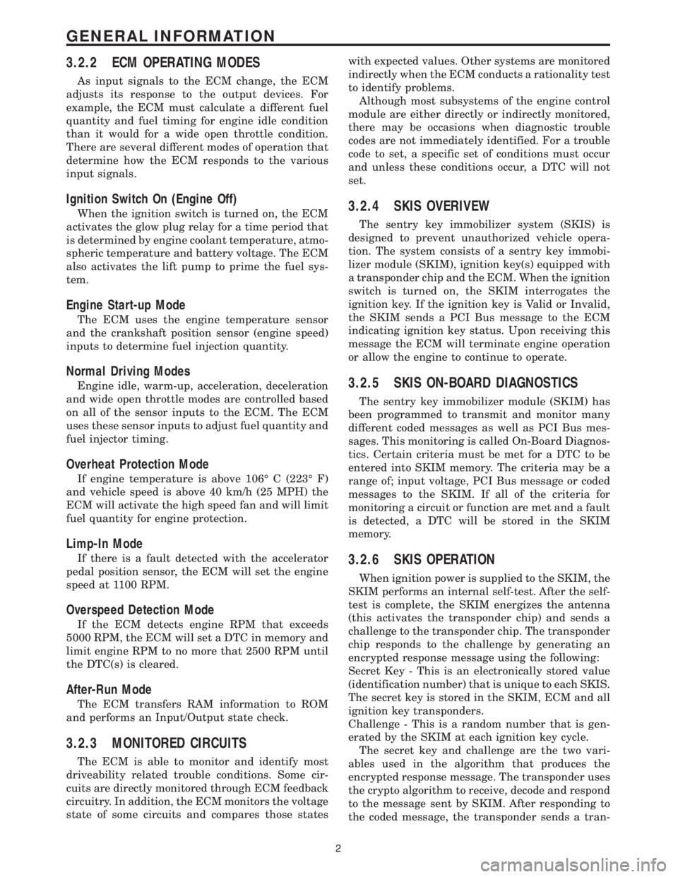
3.2.2 ECM OPERATING MODES
As input signals to the ECM change, the ECM
adjusts its response to the output devices. For
example, the ECM must calculate a different fuel
quantity and fuel timing for engine idle condition
than it would for a wide open throttle condition.
There are several different modes of operation that
determine how the ECM responds to the various
input signals.
Ignition Switch On (Engine Off)
When the ignition switch is turned on, the ECM
activates the glow plug relay for a time period that
is determined by engine coolant temperature, atmo-
spheric temperature and battery voltage. The ECM
also activates the lift pump to prime the fuel sys-
tem.
Engine Start-up Mode
The ECM uses the engine temperature sensor
and the crankshaft position sensor (engine speed)
inputs to determine fuel injection quantity.
Normal Driving Modes
Engine idle, warm-up, acceleration, deceleration
and wide open throttle modes are controlled based
on all of the sensor inputs to the ECM. The ECM
uses these sensor inputs to adjust fuel quantity and
fuel injector timing.
Overheat Protection Mode
If engine temperature is above 106É C (223É F)
and vehicle speed is above 40 km/h (25 MPH) the
ECM will activate the high speed fan and will limit
fuel quantity for engine protection.
Limp-In Mode
If there is a fault detected with the accelerator
pedal position sensor, the ECM will set the engine
speed at 1100 RPM.
Overspeed Detection Mode
If the ECM detects engine RPM that exceeds
5000 RPM, the ECM will set a DTC in memory and
limit engine RPM to no more that 2500 RPM until
the DTC(s) is cleared.
After-Run Mode
The ECM transfers RAM information to ROM
and performs an Input/Output state check.
3.2.3 MONITORED CIRCUITS
The ECM is able to monitor and identify most
driveability related trouble conditions. Some cir-
cuits are directly monitored through ECM feedback
circuitry. In addition, the ECM monitors the voltage
state of some circuits and compares those stateswith expected values. Other systems are monitored
indirectly when the ECM conducts a rationality test
to identify problems.
Although most subsystems of the engine control
module are either directly or indirectly monitored,
there may be occasions when diagnostic trouble
codes are not immediately identified. For a trouble
code to set, a specific set of conditions must occur
and unless these conditions occur, a DTC will not
set.
3.2.4 SKIS OVERIVEW
The sentry key immobilizer system (SKIS) is
designed to prevent unauthorized vehicle opera-
tion. The system consists of a sentry key immobi-
lizer module (SKIM), ignition key(s) equipped with
a transponder chip and the ECM. When the ignition
switch is turned on, the SKIM interrogates the
ignition key. If the ignition key is Valid or Invalid,
the SKIM sends a PCI Bus message to the ECM
indicating ignition key status. Upon receiving this
message the ECM will terminate engine operation
or allow the engine to continue to operate.
3.2.5 SKIS ON-BOARD DIAGNOSTICS
The sentry key immobilizer module (SKIM) has
been programmed to transmit and monitor many
different coded messages as well as PCI Bus mes-
sages. This monitoring is called On-Board Diagnos-
tics. Certain criteria must be met for a DTC to be
entered into SKIM memory. The criteria may be a
range of; input voltage, PCI Bus message or coded
messages to the SKIM. If all of the criteria for
monitoring a circuit or function are met and a fault
is detected, a DTC will be stored in the SKIM
memory.
3.2.6 SKIS OPERATION
When ignition power is supplied to the SKIM, the
SKIM performs an internal self-test. After the self-
test is complete, the SKIM energizes the antenna
(this activates the transponder chip) and sends a
challenge to the transponder chip. The transponder
chip responds to the challenge by generating an
encrypted response message using the following:
Secret Key - This is an electronically stored value
(identification number) that is unique to each SKIS.
The secret key is stored in the SKIM, ECM and all
ignition key transponders.
Challenge - This is a random number that is gen-
erated by the SKIM at each ignition key cycle.
The secret key and challenge are the two vari-
ables used in the algorithm that produces the
encrypted response message. The transponder uses
the crypto algorithm to receive, decode and respond
to the message sent by SKIM. After responding to
the coded message, the transponder sends a tran-
2
GENERAL INFORMATION
Page 1223 of 4284
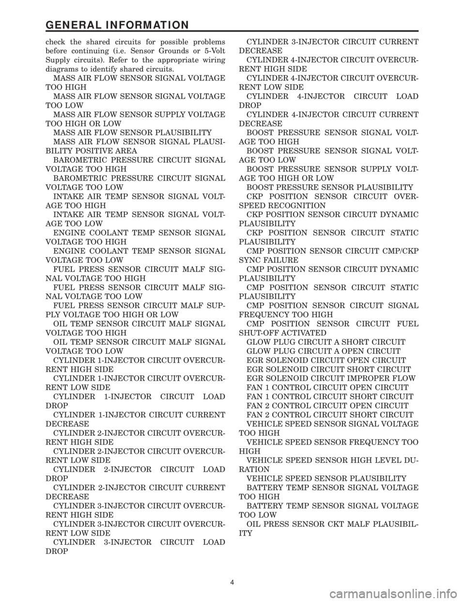
check the shared circuits for possible problems
before continuing (i.e. Sensor Grounds or 5-Volt
Supply circuits). Refer to the appropriate wiring
diagrams to identify shared circuits.
MASS AIR FLOW SENSOR SIGNAL VOLTAGE
TOO HIGH
MASS AIR FLOW SENSOR SIGNAL VOLTAGE
TOO LOW
MASS AIR FLOW SENSOR SUPPLY VOLTAGE
TOO HIGH OR LOW
MASS AIR FLOW SENSOR PLAUSIBILITY
MASS AIR FLOW SENSOR SIGNAL PLAUSI-
BILITY POSITIVE AREA
BAROMETRIC PRESSURE CIRCUIT SIGNAL
VOLTAGE TOO HIGH
BAROMETRIC PRESSURE CIRCUIT SIGNAL
VOLTAGE TOO LOW
INTAKE AIR TEMP SENSOR SIGNAL VOLT-
AGE TOO HIGH
INTAKE AIR TEMP SENSOR SIGNAL VOLT-
AGE TOO LOW
ENGINE COOLANT TEMP SENSOR SIGNAL
VOLTAGE TOO HIGH
ENGINE COOLANT TEMP SENSOR SIGNAL
VOLTAGE TOO LOW
FUEL PRESS SENSOR CIRCUIT MALF SIG-
NAL VOLTAGE TOO HIGH
FUEL PRESS SENSOR CIRCUIT MALF SIG-
NAL VOLTAGE TOO LOW
FUEL PRESS SENSOR CIRCUIT MALF SUP-
PLY VOLTAGE TOO HIGH OR LOW
OIL TEMP SENSOR CIRCUIT MALF SIGNAL
VOLTAGE TOO HIGH
OIL TEMP SENSOR CIRCUIT MALF SIGNAL
VOLTAGE TOO LOW
CYLINDER 1-INJECTOR CIRCUIT OVERCUR-
RENT HIGH SIDE
CYLINDER 1-INJECTOR CIRCUIT OVERCUR-
RENT LOW SIDE
CYLINDER 1-INJECTOR CIRCUIT LOAD
DROP
CYLINDER 1-INJECTOR CIRCUIT CURRENT
DECREASE
CYLINDER 2-INJECTOR CIRCUIT OVERCUR-
RENT HIGH SIDE
CYLINDER 2-INJECTOR CIRCUIT OVERCUR-
RENT LOW SIDE
CYLINDER 2-INJECTOR CIRCUIT LOAD
DROP
CYLINDER 2-INJECTOR CIRCUIT CURRENT
DECREASE
CYLINDER 3-INJECTOR CIRCUIT OVERCUR-
RENT HIGH SIDE
CYLINDER 3-INJECTOR CIRCUIT OVERCUR-
RENT LOW SIDE
CYLINDER 3-INJECTOR CIRCUIT LOAD
DROPCYLINDER 3-INJECTOR CIRCUIT CURRENT
DECREASE
CYLINDER 4-INJECTOR CIRCUIT OVERCUR-
RENT HIGH SIDE
CYLINDER 4-INJECTOR CIRCUIT OVERCUR-
RENT LOW SIDE
CYLINDER 4-INJECTOR CIRCUIT LOAD
DROP
CYLINDER 4-INJECTOR CIRCUIT CURRENT
DECREASE
BOOST PRESSURE SENSOR SIGNAL VOLT-
AGE TOO HIGH
BOOST PRESSURE SENSOR SIGNAL VOLT-
AGE TOO LOW
BOOST PRESSURE SENSOR SUPPLY VOLT-
AGE TOO HIGH OR LOW
BOOST PRESSURE SENSOR PLAUSIBILITY
CKP POSITION SENSOR CIRCUIT OVER-
SPEED RECOGNITION
CKP POSITION SENSOR CIRCUIT DYNAMIC
PLAUSIBILITY
CKP POSITION SENSOR CIRCUIT STATIC
PLAUSIBILITY
CMP POSITION SENSOR CIRCUIT CMP/CKP
SYNC FAILURE
CMP POSITION SENSOR CIRCUIT DYNAMIC
PLAUSIBILITY
CMP POSITION SENSOR CIRCUIT STATIC
PLAUSIBILITY
CMP POSITION SENSOR CIRCUIT SIGNAL
FREQUENCY TOO HIGH
CMP POSITION SENSOR CIRCUIT FUEL
SHUT-OFF ACTIVATED
GLOW PLUG CIRCUIT A SHORT CIRCUIT
GLOW PLUG CIRCUIT A OPEN CIRCUIT
EGR SOLENOID CIRCUIT OPEN CIRCUIT
EGR SOLENOID CIRCUIT SHORT CIRCUIT
EGR SOLENOID CIRCUIT IMPROPER FLOW
FAN 1 CONTROL CIRCUIT OPEN CIRCUIT
FAN 1 CONTROL CIRCUIT SHORT CIRCUIT
FAN 2 CONTROL CIRCUIT OPEN CIRCUIT
FAN 2 CONTROL CIRCUIT SHORT CIRCUIT
VEHICLE SPEED SENSOR SIGNAL VOLTAGE
TOO HIGH
VEHICLE SPEED SENSOR FREQUENCY TOO
HIGH
VEHICLE SPEED SENSOR HIGH LEVEL DU-
RATION
VEHICLE SPEED SENSOR PLAUSIBILITY
BATTERY TEMP SENSOR SIGNAL VOLTAGE
TOO HIGH
BATTERY TEMP SENSOR SIGNAL VOLTAGE
TOO LOW
OIL PRESS SENSOR CKT MALF PLAUSIBIL-
ITY
4
GENERAL INFORMATION