2001 CHRYSLER VOYAGER relay
[x] Cancel search: relayPage 1275 of 4284
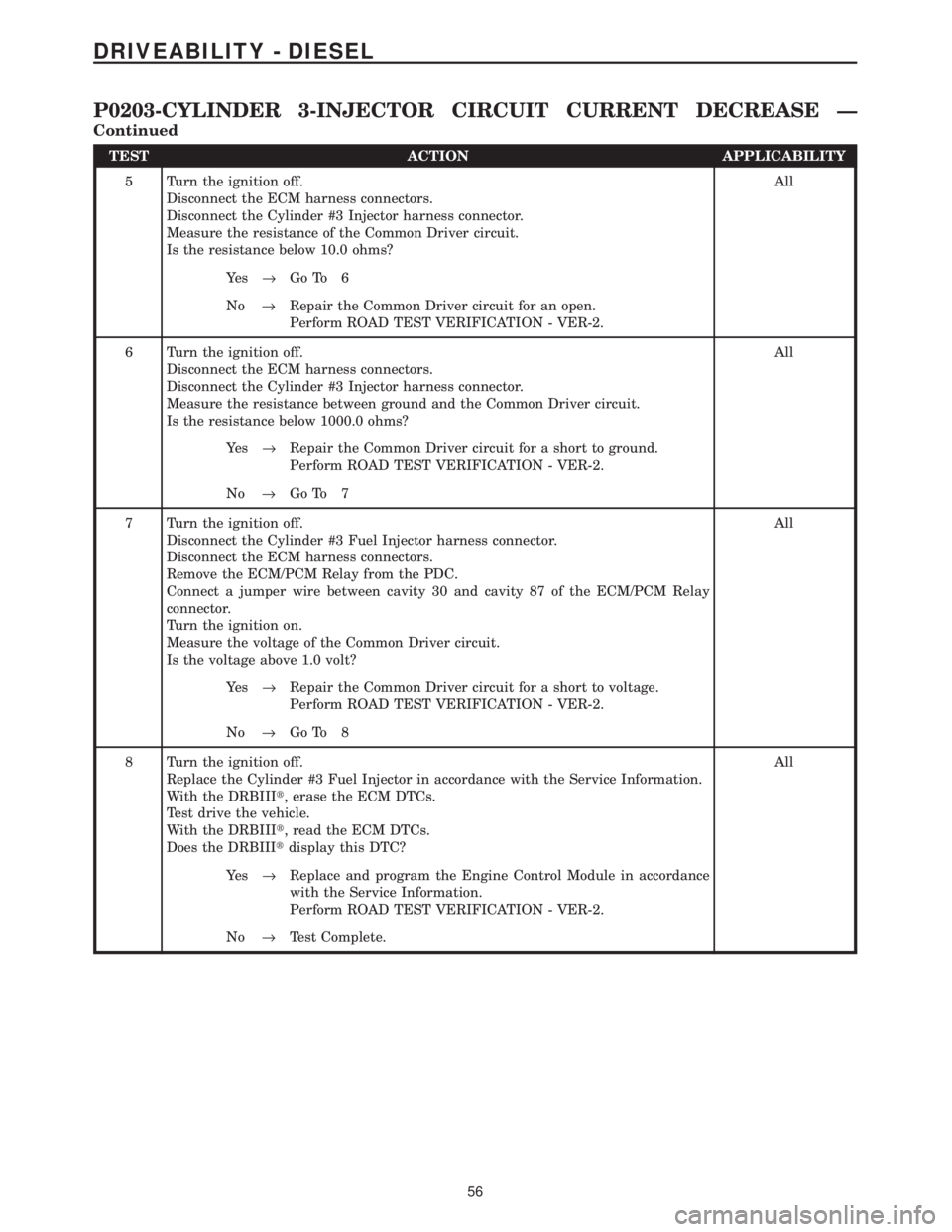
TEST ACTION APPLICABILITY
5 Turn the ignition off.
Disconnect the ECM harness connectors.
Disconnect the Cylinder #3 Injector harness connector.
Measure the resistance of the Common Driver circuit.
Is the resistance below 10.0 ohms?All
Ye s®Go To 6
No®Repair the Common Driver circuit for an open.
Perform ROAD TEST VERIFICATION - VER-2.
6 Turn the ignition off.
Disconnect the ECM harness connectors.
Disconnect the Cylinder #3 Injector harness connector.
Measure the resistance between ground and the Common Driver circuit.
Is the resistance below 1000.0 ohms?All
Ye s®Repair the Common Driver circuit for a short to ground.
Perform ROAD TEST VERIFICATION - VER-2.
No®Go To 7
7 Turn the ignition off.
Disconnect the Cylinder #3 Fuel Injector harness connector.
Disconnect the ECM harness connectors.
Remove the ECM/PCM Relay from the PDC.
Connect a jumper wire between cavity 30 and cavity 87 of the ECM/PCM Relay
connector.
Turn the ignition on.
Measure the voltage of the Common Driver circuit.
Is the voltage above 1.0 volt?All
Ye s®Repair the Common Driver circuit for a short to voltage.
Perform ROAD TEST VERIFICATION - VER-2.
No®Go To 8
8 Turn the ignition off.
Replace the Cylinder #3 Fuel Injector in accordance with the Service Information.
With the DRBIIIt, erase the ECM DTCs.
Test drive the vehicle.
With the DRBIIIt, read the ECM DTCs.
Does the DRBIIItdisplay this DTC?All
Ye s®Replace and program the Engine Control Module in accordance
with the Service Information.
Perform ROAD TEST VERIFICATION - VER-2.
No®Test Complete.
56
DRIVEABILITY - DIESEL
P0203-CYLINDER 3-INJECTOR CIRCUIT CURRENT DECREASE Ð
Continued
Page 1278 of 4284
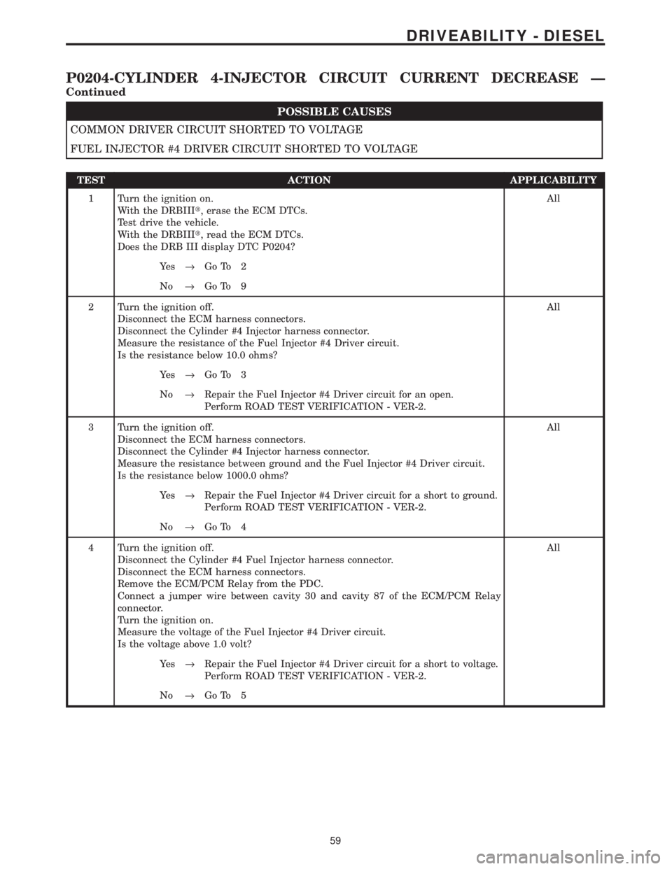
POSSIBLE CAUSES
COMMON DRIVER CIRCUIT SHORTED TO VOLTAGE
FUEL INJECTOR #4 DRIVER CIRCUIT SHORTED TO VOLTAGE
TEST ACTION APPLICABILITY
1 Turn the ignition on.
With the DRBIIIt, erase the ECM DTCs.
Test drive the vehicle.
With the DRBIIIt, read the ECM DTCs.
Does the DRB III display DTC P0204?All
Ye s®Go To 2
No®Go To 9
2 Turn the ignition off.
Disconnect the ECM harness connectors.
Disconnect the Cylinder #4 Injector harness connector.
Measure the resistance of the Fuel Injector #4 Driver circuit.
Is the resistance below 10.0 ohms?All
Ye s®Go To 3
No®Repair the Fuel Injector #4 Driver circuit for an open.
Perform ROAD TEST VERIFICATION - VER-2.
3 Turn the ignition off.
Disconnect the ECM harness connectors.
Disconnect the Cylinder #4 Injector harness connector.
Measure the resistance between ground and the Fuel Injector #4 Driver circuit.
Is the resistance below 1000.0 ohms?All
Ye s®Repair the Fuel Injector #4 Driver circuit for a short to ground.
Perform ROAD TEST VERIFICATION - VER-2.
No®Go To 4
4 Turn the ignition off.
Disconnect the Cylinder #4 Fuel Injector harness connector.
Disconnect the ECM harness connectors.
Remove the ECM/PCM Relay from the PDC.
Connect a jumper wire between cavity 30 and cavity 87 of the ECM/PCM Relay
connector.
Turn the ignition on.
Measure the voltage of the Fuel Injector #4 Driver circuit.
Is the voltage above 1.0 volt?All
Ye s®Repair the Fuel Injector #4 Driver circuit for a short to voltage.
Perform ROAD TEST VERIFICATION - VER-2.
No®Go To 5
59
DRIVEABILITY - DIESEL
P0204-CYLINDER 4-INJECTOR CIRCUIT CURRENT DECREASE Ð
Continued
Page 1279 of 4284
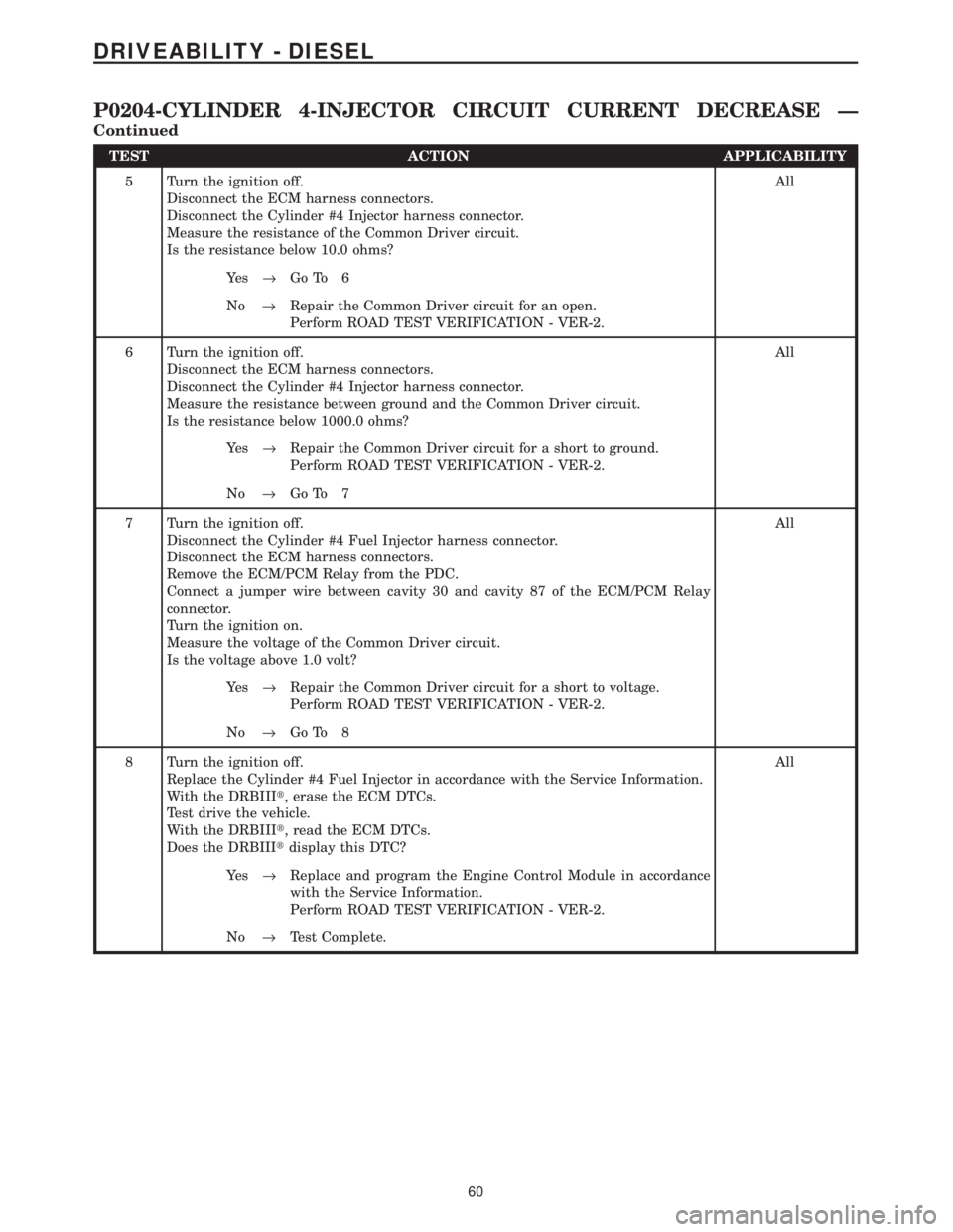
TEST ACTION APPLICABILITY
5 Turn the ignition off.
Disconnect the ECM harness connectors.
Disconnect the Cylinder #4 Injector harness connector.
Measure the resistance of the Common Driver circuit.
Is the resistance below 10.0 ohms?All
Ye s®Go To 6
No®Repair the Common Driver circuit for an open.
Perform ROAD TEST VERIFICATION - VER-2.
6 Turn the ignition off.
Disconnect the ECM harness connectors.
Disconnect the Cylinder #4 Injector harness connector.
Measure the resistance between ground and the Common Driver circuit.
Is the resistance below 1000.0 ohms?All
Ye s®Repair the Common Driver circuit for a short to ground.
Perform ROAD TEST VERIFICATION - VER-2.
No®Go To 7
7 Turn the ignition off.
Disconnect the Cylinder #4 Fuel Injector harness connector.
Disconnect the ECM harness connectors.
Remove the ECM/PCM Relay from the PDC.
Connect a jumper wire between cavity 30 and cavity 87 of the ECM/PCM Relay
connector.
Turn the ignition on.
Measure the voltage of the Common Driver circuit.
Is the voltage above 1.0 volt?All
Ye s®Repair the Common Driver circuit for a short to voltage.
Perform ROAD TEST VERIFICATION - VER-2.
No®Go To 8
8 Turn the ignition off.
Replace the Cylinder #4 Fuel Injector in accordance with the Service Information.
With the DRBIIIt, erase the ECM DTCs.
Test drive the vehicle.
With the DRBIIIt, read the ECM DTCs.
Does the DRBIIItdisplay this DTC?All
Ye s®Replace and program the Engine Control Module in accordance
with the Service Information.
Perform ROAD TEST VERIFICATION - VER-2.
No®Test Complete.
60
DRIVEABILITY - DIESEL
P0204-CYLINDER 4-INJECTOR CIRCUIT CURRENT DECREASE Ð
Continued
Page 1284 of 4284
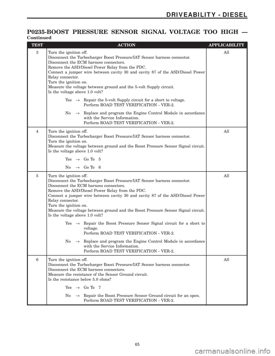
TEST ACTION APPLICABILITY
3 Turn the ignition off.
Disconnect the Turbocharger Boost Pressure/IAT Sensor harness connector.
Disconnect the ECM harness connectors.
Remove the ASD/Diesel Power Relay from the PDC.
Connect a jumper wire between cavity 30 and cavity 87 of the ASD/Diesel Power
Relay connector.
Turn the ignition on.
Measure the voltage between ground and the 5-volt Supply circuit.
Is the voltage above 1.0 volt?All
Ye s®Repair the 5-volt Supply circuit for a short to voltage.
Perform ROAD TEST VERIFICATION - VER-2.
No®Replace and program the Engine Control Module in accordance
with the Service Information.
Perform ROAD TEST VERIFICATION - VER-2.
4 Turn the ignition off.
Disconnect the Turbocharger Boost Pressure/IAT Sensor harness connector.
Turn the ignition on.
Measure the voltage between ground and the Boost Pressure Sensor Signal circuit.
Is the voltage above 1.0 volt?All
Ye s®Go To 5
No®Go To 6
5 Turn the ignition off.
Disconnect the Turbocharger Boost Pressure/IAT Sensor harness connector.
Disconnect the ECM harness connectors.
Remove the ASD/Diesel Power Relay from the PDC.
Connect a jumper wire between cavity 30 and cavity 87 of the ASD/Diesel Power
Relay connector.
Turn the ignition on.
Measure the voltage between ground and the Boost Pressure Sensor Signal circuit.
Is the voltage above 1.0 volt?All
Ye s®Repair the Boost Pressure Sensor Signal circuit for a short to
voltage.
Perform ROAD TEST VERIFICATION - VER-2.
No®Replace and program the Engine Control Module in accordance
with the Service Information.
Perform ROAD TEST VERIFICATION - VER-2.
6 Turn the ignition off.
Disconnect the Turbocharger Boost Pressure/IAT Sensor harness connector.
Disconnect the ECM harness connectors.
Measure the resistance of the Sensor Ground circuit.
Is the resistance below 5.0 ohms?All
Ye s®Go To 7
No®Repair the Boost Pressure Sensor Ground circuit for an open.
Perform ROAD TEST VERIFICATION - VER-2.
65
DRIVEABILITY - DIESEL
P0235-BOOST PRESSURE SENSOR SIGNAL VOLTAGE TOO HIGH Ð
Continued
Page 1289 of 4284
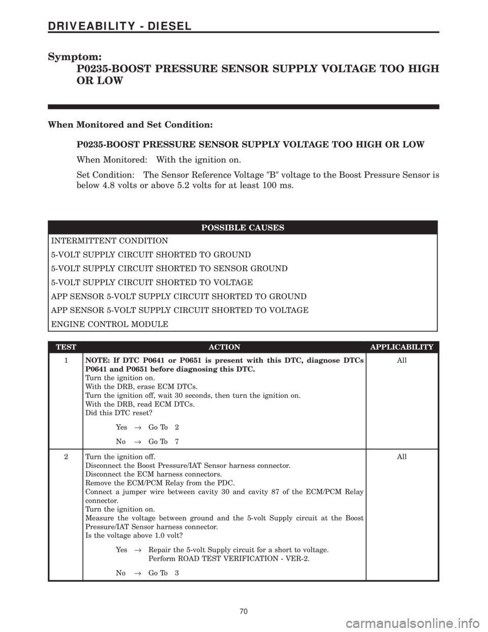
Symptom:
P0235-BOOST PRESSURE SENSOR SUPPLY VOLTAGE TOO HIGH
OR LOW
When Monitored and Set Condition:
P0235-BOOST PRESSURE SENSOR SUPPLY VOLTAGE TOO HIGH OR LOW
When Monitored: With the ignition on.
Set Condition: The Sensor Reference Voltage9B9voltage to the Boost Pressure Sensor is
below 4.8 volts or above 5.2 volts for at least 100 ms.
POSSIBLE CAUSES
INTERMITTENT CONDITION
5-VOLT SUPPLY CIRCUIT SHORTED TO GROUND
5-VOLT SUPPLY CIRCUIT SHORTED TO SENSOR GROUND
5-VOLT SUPPLY CIRCUIT SHORTED TO VOLTAGE
APP SENSOR 5-VOLT SUPPLY CIRCUIT SHORTED TO GROUND
APP SENSOR 5-VOLT SUPPLY CIRCUIT SHORTED TO VOLTAGE
ENGINE CONTROL MODULE
TEST ACTION APPLICABILITY
1NOTE: If DTC P0641 or P0651 is present with this DTC, diagnose DTCs
P0641 and P0651 before diagnosing this DTC.
Turn the ignition on.
With the DRB, erase ECM DTCs.
Turn the ignition off, wait 30 seconds, then turn the ignition on.
With the DRB, read ECM DTCs.
Did this DTC reset?All
Ye s®Go To 2
No®Go To 7
2 Turn the ignition off.
Disconnect the Boost Pressure/IAT Sensor harness connector.
Disconnect the ECM harness connectors.
Remove the ECM/PCM Relay from the PDC.
Connect a jumper wire between cavity 30 and cavity 87 of the ECM/PCM Relay
connector.
Turn the ignition on.
Measure the voltage between ground and the 5-volt Supply circuit at the Boost
Pressure/IAT Sensor harness connector.
Is the voltage above 1.0 volt?All
Ye s®Repair the 5-volt Supply circuit for a short to voltage.
Perform ROAD TEST VERIFICATION - VER-2.
No®Go To 3
70
DRIVEABILITY - DIESEL
Page 1290 of 4284
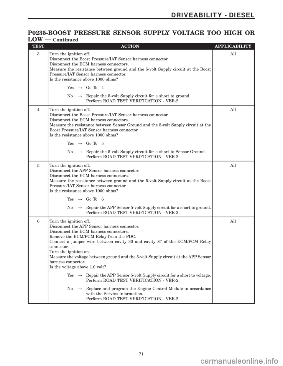
TEST ACTION APPLICABILITY
3 Turn the ignition off.
Disconnect the Boost Pressure/IAT Sensor harness connector.
Disconnect the ECM harness connectors.
Measure the resistance between ground and the 5-volt Supply circuit at the Boost
Pressure/IAT Sensor harness connector.
Is the resistance above 1000 ohms?All
Ye s®Go To 4
No®Repair the 5-volt Supply circuit for a short to ground.
Perform ROAD TEST VERIFICATION - VER-2.
4 Turn the ignition off.
Disconnect the Boost Pressure/IAT Sensor harness connector.
Disconnect the ECM harness connectors.
Measure the resistance between Sensor Ground and the 5-volt Supply circuit at the
Boost Pressure/IAT Sensor harness connector.
Is the resistance above 1000 ohms?All
Ye s®Go To 5
No®Repair the 5-volt Supply circuit for a short to Sensor Ground.
Perform ROAD TEST VERIFICATION - VER-2.
5 Turn the ignition off.
Disconnect the APP Sensor harness connector.
Disconnect the ECM harness connectors.
Measure the resistance between ground and the 5-volt Supply circuit at the Boost
Pressure/IAT Sensor harness connector.
Is the resistance above 1000 ohms?All
Ye s®Go To 6
No®Repair the APP Sensor 5-volt Supply circuit for a short to ground.
Perform ROAD TEST VERIFICATION - VER-2.
6 Turn the ignition off.
Disconnect the APP Sensor harness connector.
Disconnect the ECM harness connectors.
Remove the ECM/PCM Relay from the PDC.
Connect a jumper wire between cavity 30 and cavity 87 of the ECM/PCM Relay
connector.
Turn the ignition on.
Measure the voltage between ground and the 5-volt Supply circuit at the APP Sensor
harness connector.
Is the voltage above 1.0 volt?All
Ye s®Repair the APP Sensor 5-volt Supply circuit for a short to voltage.
Perform ROAD TEST VERIFICATION - VER-2.
No®Replace and program the Engine Control Module in accordance
with the Service Information.
Perform ROAD TEST VERIFICATION - VER-2.
71
DRIVEABILITY - DIESEL
P0235-BOOST PRESSURE SENSOR SUPPLY VOLTAGE TOO HIGH OR
LOW Ð
Continued
Page 1299 of 4284
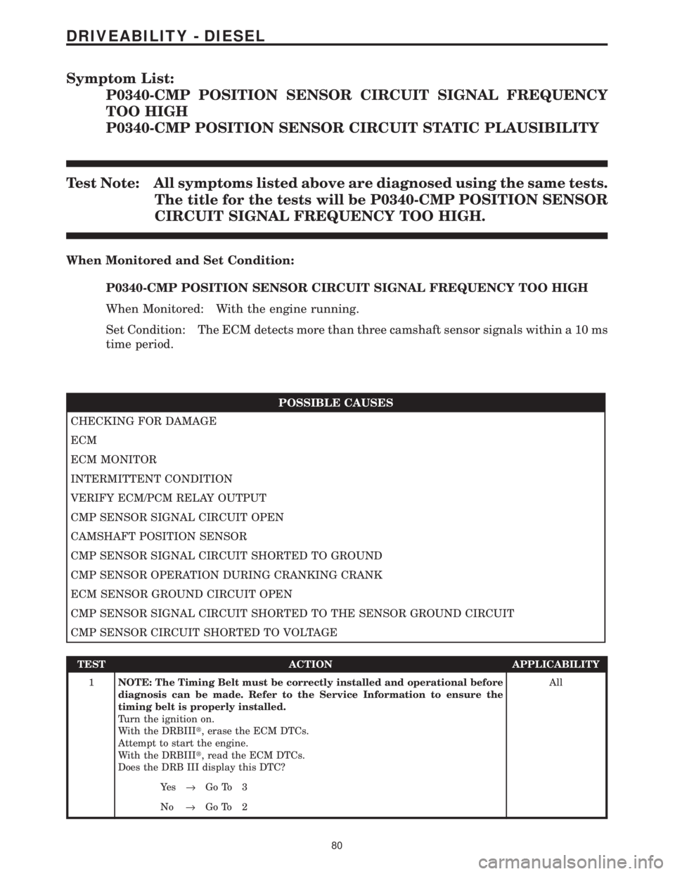
Symptom List:
P0340-CMP POSITION SENSOR CIRCUIT SIGNAL FREQUENCY
TOO HIGH
P0340-CMP POSITION SENSOR CIRCUIT STATIC PLAUSIBILITY
Test Note: All symptoms listed above are diagnosed using the same tests.
The title for the tests will be P0340-CMP POSITION SENSOR
CIRCUIT SIGNAL FREQUENCY TOO HIGH.
When Monitored and Set Condition:
P0340-CMP POSITION SENSOR CIRCUIT SIGNAL FREQUENCY TOO HIGH
When Monitored: With the engine running.
Set Condition: The ECM detects more than three camshaft sensor signals within a 10 ms
time period.
POSSIBLE CAUSES
CHECKING FOR DAMAGE
ECM
ECM MONITOR
INTERMITTENT CONDITION
VERIFY ECM/PCM RELAY OUTPUT
CMP SENSOR SIGNAL CIRCUIT OPEN
CAMSHAFT POSITION SENSOR
CMP SENSOR SIGNAL CIRCUIT SHORTED TO GROUND
CMP SENSOR OPERATION DURING CRANKING CRANK
ECM SENSOR GROUND CIRCUIT OPEN
CMP SENSOR SIGNAL CIRCUIT SHORTED TO THE SENSOR GROUND CIRCUIT
CMP SENSOR CIRCUIT SHORTED TO VOLTAGE
TEST ACTION APPLICABILITY
1NOTE: The Timing Belt must be correctly installed and operational before
diagnosis can be made. Refer to the Service Information to ensure the
timing belt is properly installed.
Turn the ignition on.
With the DRBIIIt, erase the ECM DTCs.
Attempt to start the engine.
With the DRBIIIt, read the ECM DTCs.
Does the DRB III display this DTC?All
Ye s®Go To 3
No®Go To 2
80
DRIVEABILITY - DIESEL
Page 1300 of 4284
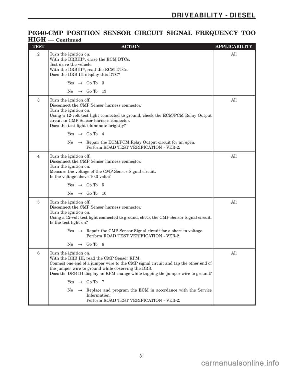
TEST ACTION APPLICABILITY
2 Turn the ignition on.
With the DRBIIIt, erase the ECM DTCs.
Test drive the vehicle.
With the DRBIIIt, read the ECM DTCs.
Does the DRB III display this DTC?All
Ye s®Go To 3
No®Go To 13
3 Turn the ignition off.
Disconnect the CMP Sensor harness connector.
Turn the ignition on.
Using a 12-volt test light connected to ground, check the ECM/PCM Relay Output
circuit in CMP Sensor harness connector.
Does the test light illuminate brightly?All
Ye s®Go To 4
No®Repair the ECM/PCM Relay Output circuit for an open.
Perform ROAD TEST VERIFICATION - VER-2.
4 Turn the ignition off.
Disconnect the CMP Sensor harness connector.
Turn the ignition on.
Measure the voltage of the CMP Sensor Signal circuit.
Is the voltage above 10.0 volts?All
Ye s®Go To 5
No®Go To 10
5 Turn the ignition off.
Disconnect the CMP Sensor harness connector.
Turn the ignition on.
Using a 12-volt test light connected to ground, check the CMP Sensor Signal circuit.
Is the test light on?All
Ye s®Repair the CMP Sensor Signal circuit for a short to voltage.
Perform ROAD TEST VERIFICATION - VER-2.
No®Go To 6
6 Turn the ignition on.
With the DRB III, read the CMP Sensor RPM.
Connect one end of a jumper wire to the CMP signal circuit and tap the other end of
the jumper wire to ground while observing the DRB.
Does the DRB III display an RPM change while tapping the jumper wire to ground?All
Ye s®Go To 7
No®Replace and program the ECM in accordance with the Service
Information.
Perform ROAD TEST VERIFICATION - VER-2.
81
DRIVEABILITY - DIESEL
P0340-CMP POSITION SENSOR CIRCUIT SIGNAL FREQUENCY TOO
HIGH Ð
Continued