2001 CHRYSLER VOYAGER relay
[x] Cancel search: relayPage 1221 of 4284
3.2.2 ECM OPERATING MODES
As input signals to the ECM change, the ECM
adjusts its response to the output devices. For
example, the ECM must calculate a different fuel
quantity and fuel timing for engine idle condition
than it would for a wide open throttle condition.
There are several different modes of operation that
determine how the ECM responds to the various
input signals.
Ignition Switch On (Engine Off)
When the ignition switch is turned on, the ECM
activates the glow plug relay for a time period that
is determined by engine coolant temperature, atmo-
spheric temperature and battery voltage. The ECM
also activates the lift pump to prime the fuel sys-
tem.
Engine Start-up Mode
The ECM uses the engine temperature sensor
and the crankshaft position sensor (engine speed)
inputs to determine fuel injection quantity.
Normal Driving Modes
Engine idle, warm-up, acceleration, deceleration
and wide open throttle modes are controlled based
on all of the sensor inputs to the ECM. The ECM
uses these sensor inputs to adjust fuel quantity and
fuel injector timing.
Overheat Protection Mode
If engine temperature is above 106É C (223É F)
and vehicle speed is above 40 km/h (25 MPH) the
ECM will activate the high speed fan and will limit
fuel quantity for engine protection.
Limp-In Mode
If there is a fault detected with the accelerator
pedal position sensor, the ECM will set the engine
speed at 1100 RPM.
Overspeed Detection Mode
If the ECM detects engine RPM that exceeds
5000 RPM, the ECM will set a DTC in memory and
limit engine RPM to no more that 2500 RPM until
the DTC(s) is cleared.
After-Run Mode
The ECM transfers RAM information to ROM
and performs an Input/Output state check.
3.2.3 MONITORED CIRCUITS
The ECM is able to monitor and identify most
driveability related trouble conditions. Some cir-
cuits are directly monitored through ECM feedback
circuitry. In addition, the ECM monitors the voltage
state of some circuits and compares those stateswith expected values. Other systems are monitored
indirectly when the ECM conducts a rationality test
to identify problems.
Although most subsystems of the engine control
module are either directly or indirectly monitored,
there may be occasions when diagnostic trouble
codes are not immediately identified. For a trouble
code to set, a specific set of conditions must occur
and unless these conditions occur, a DTC will not
set.
3.2.4 SKIS OVERIVEW
The sentry key immobilizer system (SKIS) is
designed to prevent unauthorized vehicle opera-
tion. The system consists of a sentry key immobi-
lizer module (SKIM), ignition key(s) equipped with
a transponder chip and the ECM. When the ignition
switch is turned on, the SKIM interrogates the
ignition key. If the ignition key is Valid or Invalid,
the SKIM sends a PCI Bus message to the ECM
indicating ignition key status. Upon receiving this
message the ECM will terminate engine operation
or allow the engine to continue to operate.
3.2.5 SKIS ON-BOARD DIAGNOSTICS
The sentry key immobilizer module (SKIM) has
been programmed to transmit and monitor many
different coded messages as well as PCI Bus mes-
sages. This monitoring is called On-Board Diagnos-
tics. Certain criteria must be met for a DTC to be
entered into SKIM memory. The criteria may be a
range of; input voltage, PCI Bus message or coded
messages to the SKIM. If all of the criteria for
monitoring a circuit or function are met and a fault
is detected, a DTC will be stored in the SKIM
memory.
3.2.6 SKIS OPERATION
When ignition power is supplied to the SKIM, the
SKIM performs an internal self-test. After the self-
test is complete, the SKIM energizes the antenna
(this activates the transponder chip) and sends a
challenge to the transponder chip. The transponder
chip responds to the challenge by generating an
encrypted response message using the following:
Secret Key - This is an electronically stored value
(identification number) that is unique to each SKIS.
The secret key is stored in the SKIM, ECM and all
ignition key transponders.
Challenge - This is a random number that is gen-
erated by the SKIM at each ignition key cycle.
The secret key and challenge are the two vari-
ables used in the algorithm that produces the
encrypted response message. The transponder uses
the crypto algorithm to receive, decode and respond
to the message sent by SKIM. After responding to
the coded message, the transponder sends a tran-
2
GENERAL INFORMATION
Page 1222 of 4284
sponder ID message to the SKIM. The SKIM com-
pares the transponder ID message to the available
valid key codes in SKIM memory (8 key maximum
at any one time). After validating the ignition key,
the SKIM sends a PCI Bus message called a seed
request to the ECM, then waits for the ECM re-
sponse. If the ECM does not respond, the SKIM will
send the seed request again. After three failed
attempts, the SKIM will stop sending the seed
request and store a trouble code in memory. If the
ECM sends a seed response, the SKIM sends a
valid/invalid key message to the ECM. This is an
encrypted message that is generated using the
following:
VIN - Vehicle Identification Number.
Seed - This is a random number that is generated
by the ECM at each ignition key cycle.
The VIN and seed are two variables used in the
rolling code algorithm that encrypts the valid/
invalid key message. The ECM uses the rolling code
algorithm to receive, decode and respond to the
valid/invalid key message sent by the SKIM. After
sending the valid/invalid key message, the SKIM
waits 3.5 seconds for an ECM status message from
the ECM. If the ECM does not respond with a valid
key message to the SKIM, a fault is detected and a
code is stored.
The SKIS incorporates a warning lamp located in
the information center. The lamp receives switched
ignition voltage and is hardwired to the body con-
trol module. The lamp is actuated when the SKIM
sends a PCI Bus message to the body control
module requesting the lamp on. The body control
module then provides the ground for the lamp.
The SKIM will request lamp operation for the
following:
± bulb check at ignition on
± to alert the vehicle operator to a SKIS malfunc-
tion
± when the SKIM is in customer key programming
mode
For all faults except transponder faults the lamp
remains on steady. In the event of a transponder
fault the lamp will flash at a rate of 1Hz (once per
second). If a fault is present, the lamp will remain
on or flashing for the complete ignition cycle. If a
fault is stored in SKIM memory which prevents the
system from operating properly, the ECM will allow
the engine to start and idle for 2 seconds then stall.
This may occur up to six times. After the sixth
attempt, the ECM disables the starter relay until
the fault is corrected.
3.3 DIAGNOSTIC TROUBLE CODES
Each diagnostic trouble code (DTC) is diagnosed
by following a specific procedure. The diagnostic
test procedure contains step-by-step instruction fordetermining the cause of the DTC as well as no
trouble code problems. It is not necessary to per-
form all of the tests in this book to diagnose an
individual code.
Always begin diagnosis by reading the DTC's
using the DRBIIIt.
3.3.1 HARD CODE
A DTC that comes back within one cycle of the
ignition key is a hard code. This means that the
problem is current every time the ECM/SKIM
checks that circuit or function. Procedures in this
manual verify if the DTC is a hard code at the
beginning of each test. When the fault is not a hard
code, an intermittent test must be performed.
NOTE: If the DRBIIItdisplays faults for multiple
components (i.e. ECT, VSS, Oil Temp sensors) iden-
tify and check the shared circuits for possible prob-
lems before continuing (i.e. sensor grounds or 5-volt
supply circuits). Refer to the appropriate schematic
to identify shared circuits.
3.3.2 INTERMITTENT CODE
A DTC that is not current every time the ECM/
SKIM checks the circuit or function is an intermit-
tent code. Most intermittent DTCs are caused by
wiring or connector problems. Problems that come
and go like this are the most difficult to diagnose;
they must be looked for under specific conditions
that cause them. The following checks may assist
you in identifying a possible intermittent problem.
²Visually inspect the related wire harness connec-
tors. Look for broken, bent, pushed out, or cor-
roded terminals.
²Visually inspect the related wire harness. Look
for chafed, pierced, or partially broken wire.
²Refer to hotlines or technical service bulletins
that may apply.
NOTE: Electromagnetic (radio) interference can
cause an intermittent system malfunction. This
interference can interrupt communication between
the ignition key transponder and the SKIM.
3.3.3 ECM DIAGNOSTIC TROUBLE CODES
IMPORTANT NOTE:Before replacing the ECM
for a failed driver, control circuit or ground circuit,
be sure to check the related component/circuit in-
tegrity for failures not detected due to a double fault
in the circuit. Most ECM driver/control circuit fail-
ures are caused by internal failures to components
(i.e. relays and solenoids) and shorted circuits (i.e.
sensor pull-ups, drivers and ground circuits). These
faults are difficult to detect when a double fault has
occurred and only one DTC has set.
If the DRB displays faults for multiple compo-
nents (i.e. VSS, ECT, Batt Temp, etc.), identify and
3
GENERAL INFORMATION
Page 1224 of 4284
A/C PRESSURE SENSOR CIRCUIT SIGNAL
VOLTAGE TOO HIGH
A/C PRESSURE SENSOR CIRCUIT SIGNAL
VOLTAGE TOO LOW
A/C PRESSURE SENSOR CIRCUIT SUPPLY
VOLTAGE TOO HIGH OR LOW
A/C PRESSURE SENSOR CIRCUIT PLAUSI-
BILITY
SYSTEM VOLTAGE TOO HIGH
SYSTEM VOLTAGE TOO LOW
S/C SWITCH SIGNAL CIRCUIT SIGNAL VOLT-
AGE TOO HIGH
S/C SWITCH SIGNAL CIRCUIT SIGNAL VOLT-
AGE TOO LOW
S/C SWITCH SIGNAL CIRCUIT PLAUSIBILITY
ECM ERROR RECOVERY HAS OCCURRED
ECM ERROR REDUNDANT OVERRUN MONI-
TORING
ECM ERROR GATE ARRAY - QUANTITY STOP
ECM ERROR GATE ARRAY - COMMUNICA-
TION
ECM ERROR - COMMUNICATION NOT VERI-
FIED
STARTER RELAY CIRCUIT OPEN CIRCUIT
STARTER RELAY CIRCUIT SHORT CIRCUIT
GENERATOR FIELD CONTROL MALF BAT-
TERY VOLTAGE TOO HIGH
GENERATOR FIELD CONTROL MALF BAT-
TERY VOLTAGE TOO LOW
GENERATOR FIELD CONTROL MALF OPEN
CIRCUIT
GENERATOR FIELD CONTROL MALF SHORT
CIRCUIT
GENERATOR FIELD CONTROL MALF
CHARGING VOLTS TOO LOW
GENERATOR FIELD CONTROL MALF BAT-
TERY VOLTAGE DEVIATION TOO HIGH
GENERATOR FIELD CONTROL MALF BAT-
TERY VOLTAGE DEVIATION TOO LOW
GENERATOR FIELD CONTROL MALF UN-
STABLE CURRENT
SENSOR REFERENCE VOLTAGE A CKT VOLT-
AGE TOO HIGH
SENSOR REFERENCE VOLTAGE A CKT VOLT-
AGE TOO LOW
SENSOR REFERENCE VOLTAGE B CKT
VOLTAGE TOO HIGH
SENSOR REFERENCE VOLTAGE B CKT
VOLTAGE TOO LOW
A/C CLUTCH RELAY CIRCUIT OPEN CIRCUIT
A/C CLUTCH RELAY CIRCUIT SHORT CIR-
CUIT
ECM/PCM RELAY CONTROL CIRCUIT SHUTS
OFF TOO EARLY
ECM/PCM RELAY CONTROL CIRCUIT SHUTS
OFF TOO LATE
BRAKE SWITCH SIGNAL CIRCUITS INCOR-
RECT CAN MESSAGEBRAKE SWITCH SIGNAL CIRCUITS PLAUSI-
BILITY WITH REDUNDANT CONTACT
BRAKE SWITCH SIGNAL CIRCUITS PLAUSI-
BILITY WITH REDUNDANT CONTACT AFTER
INITIALIZATION
CLUTCH UPSTOP SWITCH PERF PLAUSIBIL-
ITY
CLUTCH UPSTOP SWITCH PERF PLAUSIBIL-
ITY WITH P/N SWITCH
FUEL RAIL PRESSURE MALFUNCTION
PRESSURE TOO HIGH - LIMITATION
FUEL RAIL PRESSURE MALFUNCTION
PRESSURE TOO LOW
FUEL RAIL PRESSURE MALFUNCTION SO-
LENOID OPEN
FUEL RAIL PRESSURE MALFUNCTION
LEAKAGE DETECTED
FUEL PRESSURE SOLENOID OPEN CIRCUIT
FUEL PRESSURE SOLENOID SHORT CIR-
CUIT
FUEL PRESSURE SOLENOID PLAUSIBILITY
IN AFTER-RUN
CALCULATED INJECTOR VOLTAGE - VOLT-
AGE 1 TOO LOW
CALCULATED INJECTOR VOLTAGE - VOLT-
AGE 2 TOO LOW
BATTERY SENSE LINE 1 VOLTAGE TOO
HIGH
BATTERY SENSE LINE 1 VOLTAGE TOO LOW
FUEL PRESS REG CURRENT CONTROL SIG-
NAL TOO HIGH
FUEL PRESS REG CURRENT CONTROL SIG-
NAL TOO LOW
GENERATOR FIELD CURRENT TOO HIGH
GENERATOR FIELD CURRENT TOO LOW
CAPACITOR VOLTAGE 1 VOLTAGE TOO HIGH
CAPACITOR VOLTAGE 1 VOLTAGE TOO LOW
CAPACITOR VOLTAGE 2 VOLTAGE TOO HIGH
CAPACITOR VOLTAGE 2 VOLTAGE TOO LOW
IGNITION SWITCH PLAUSIBILITY
AFTER RUN SHUT OFF ERROR - ZERO
QUANTITY
AFTERRUN SHUT OFF ERROR - INJ. POWER-
STAGE
VOLTAGE REGULATOR SIGNAL VOLTAGE
TOO HIGH
VOLTAGE REGULATOR SIGNAL VOLTAGE
TOO LOW
MIL/DIAG LAMP VIA J1850 BUS IN FRAME
RESPONSE ERROR
MIL/DIAG LAMP VIA J1850 BUS - STATUS
ERROR
J1850 COMMUNICATION BUS SHORT TO
VOLTAGE
J1850 COMMUNICATION BUS SHORT TO
GROUND
J1850 COMMUNICATION BUS TRANSMIT
BUFFER OVERRUN
5
GENERAL INFORMATION
Page 1232 of 4284
Symptom List:
P0100-MASS AIR FLOW SENSOR PLAUSIBILITY
P0100-MASS AIR FLOW SENSOR PLAUSIBILITY POSITIVE AREA
P0100-MASS AIR FLOW SENSOR SIGNAL VOLTAGE TOO HIGH
P0100-MASS AIR FLOW SENSOR SIGNAL VOLTAGE TOO LOW
P0100-MASS AIR FLOW SENSOR SUPPLY VOLTAGE TOO HIGH OR
LOW
Test Note: All symptoms listed above are diagnosed using the same tests.
The title for the tests will be P0100-MASS AIR FLOW SENSOR
PLAUSIBILITY.
When Monitored and Set Condition:
P0100-MASS AIR FLOW SENSOR PLAUSIBILITY
When Monitored: With the engine running.
Set Condition: The mass airflow measure does not correspond with the enigne load
measurements.
P0100-MASS AIR FLOW SENSOR SIGNAL VOLTAGE TOO HIGH
When Monitored: With the ignition on.
Set Condition: The Boost Pressure Sensor Signal voltage is above 4.5 volts.
P0100-MASS AIR FLOW SENSOR SIGNAL VOLTAGE TOO LOW
When Monitored: With the ignition on.
Set Condition: The Mass Air Flow Sensor Signal voltage is below 0.2 volt.
P0100-MASS AIR FLOW SENSOR SUPPLY VOLTAGE TOO HIGH OR LOW
When Monitored: With the ignition on.
Set Condition: The Sensor Reference Voltage9A9voltage to the MAF is below 4.8 volts or
above 5.2 volts for at least 100 ms.
POSSIBLE CAUSES
ECM - 5-VOLT SUPPLY CIRCUIT
ECM/PCM RELAY OUTPUT CIRCUIT OPEN
MAF SENSOR IDLE VOLTAGE
MAF SENSOR SIGNAL - FULL THROTTLE VOLTAGE
SENSOR GROUND OPEN
INTERMITTENT CONDITION
5-VOLT SUPPLY CIRCUIT OPEN
13
DRIVEABILITY - DIESEL
Page 1234 of 4284
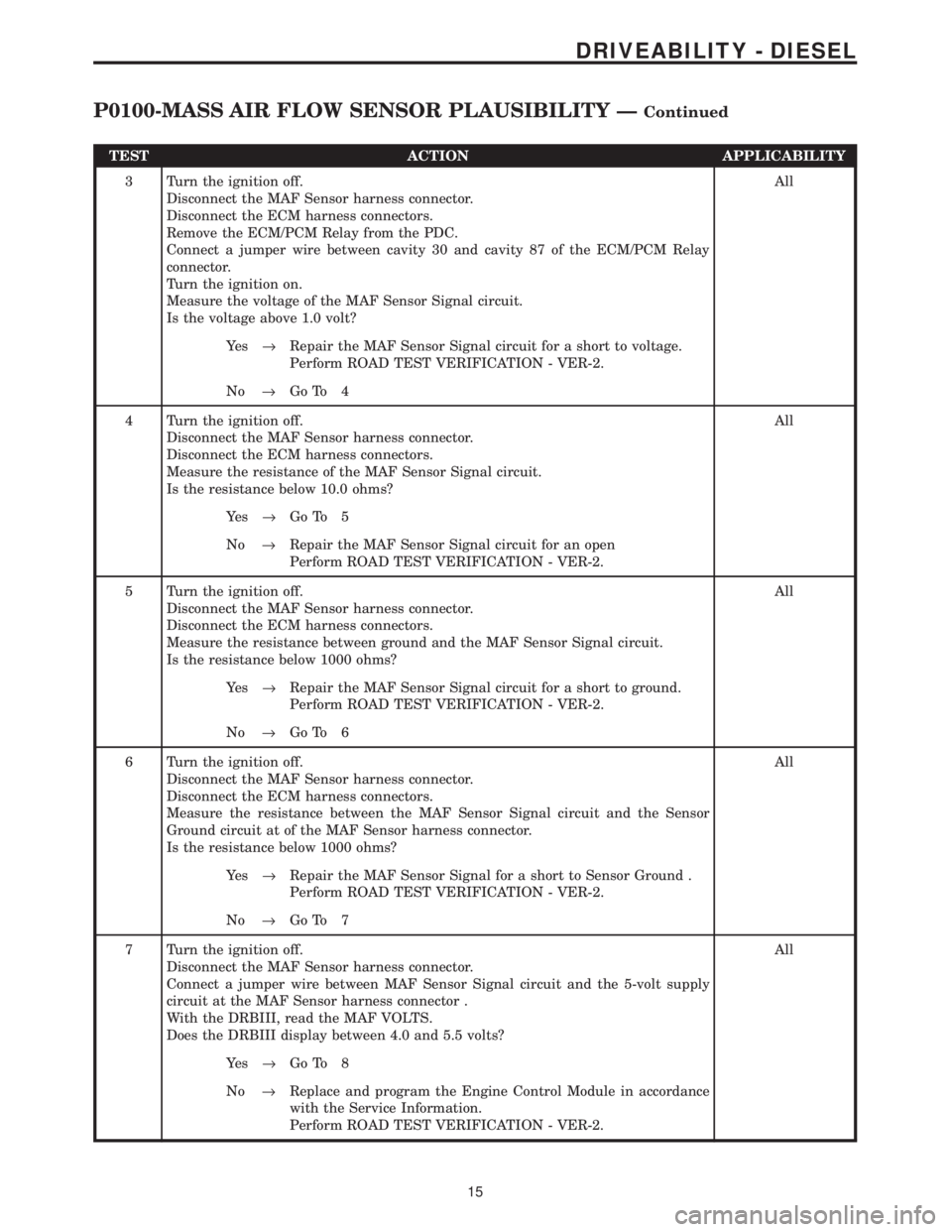
TEST ACTION APPLICABILITY
3 Turn the ignition off.
Disconnect the MAF Sensor harness connector.
Disconnect the ECM harness connectors.
Remove the ECM/PCM Relay from the PDC.
Connect a jumper wire between cavity 30 and cavity 87 of the ECM/PCM Relay
connector.
Turn the ignition on.
Measure the voltage of the MAF Sensor Signal circuit.
Is the voltage above 1.0 volt?All
Ye s®Repair the MAF Sensor Signal circuit for a short to voltage.
Perform ROAD TEST VERIFICATION - VER-2.
No®Go To 4
4 Turn the ignition off.
Disconnect the MAF Sensor harness connector.
Disconnect the ECM harness connectors.
Measure the resistance of the MAF Sensor Signal circuit.
Is the resistance below 10.0 ohms?All
Ye s®Go To 5
No®Repair the MAF Sensor Signal circuit for an open
Perform ROAD TEST VERIFICATION - VER-2.
5 Turn the ignition off.
Disconnect the MAF Sensor harness connector.
Disconnect the ECM harness connectors.
Measure the resistance between ground and the MAF Sensor Signal circuit.
Is the resistance below 1000 ohms?All
Ye s®Repair the MAF Sensor Signal circuit for a short to ground.
Perform ROAD TEST VERIFICATION - VER-2.
No®Go To 6
6 Turn the ignition off.
Disconnect the MAF Sensor harness connector.
Disconnect the ECM harness connectors.
Measure the resistance between the MAF Sensor Signal circuit and the Sensor
Ground circuit at of the MAF Sensor harness connector.
Is the resistance below 1000 ohms?All
Ye s®Repair the MAF Sensor Signal for a short to Sensor Ground .
Perform ROAD TEST VERIFICATION - VER-2.
No®Go To 7
7 Turn the ignition off.
Disconnect the MAF Sensor harness connector.
Connect a jumper wire between MAF Sensor Signal circuit and the 5-volt supply
circuit at the MAF Sensor harness connector .
With the DRBIII, read the MAF VOLTS.
Does the DRBIII display between 4.0 and 5.5 volts?All
Ye s®Go To 8
No®Replace and program the Engine Control Module in accordance
with the Service Information.
Perform ROAD TEST VERIFICATION - VER-2.
15
DRIVEABILITY - DIESEL
P0100-MASS AIR FLOW SENSOR PLAUSIBILITY ÐContinued
Page 1235 of 4284

TEST ACTION APPLICABILITY
8 Turn the ignition off.
Disconnect the MAF Sensor harness connector.
Disconnect the ECM harness connectors.
Measure the resistance of the Sensor Ground circuit between the MAF Sensor and
the ECM.
Is the resistance below 10.0 ohms?All
Ye s®Go To 9
No®Repair the Sensor Ground circuit for an open.
Perform ROAD TEST VERIFICATION - VER-2.
9 Turn the ignition off.
Disconnect the MAF Sensor harness connector.
Measure the voltage between the 5-volt Supply circuit and the Sensor Ground circuit
at the MAF Sensor harness connector.
Is the voltage above 4.5 volts?All
Ye s®Go To 10
No®Replace and program the ECM in accordance with the Service
Information.
Perform ROAD TEST VERIFICATION - VER-2.
10 Turn the ignition off.
Disconnect the MAF Sensor harness connector.
With the DRBIIIt, actuate the ECM/PCM Relay.
Measure the voltage of the 12-volt Supply circuit at the MAF Sensor harness
connector
Is the voltage above 10.0 volts?All
Ye s®Go To 11
No®Repair the ECM/PCM Relay Output circuit for an open.
Perform ROAD TEST VERIFICATION - VER-2.
11 Turn the ignition off.
NOTE: Inspect the turbocharger inlet tube between the MAF Sensor and the
Turbocharger. Ensure the airflow tube properly is secured at each end and
that there is no damage, restrictions or air leaks in the tube.
With a voltmeter, backprobe the MAF Sensor Signal circuit at the MAF Sensor
harness connector.
Allow the engine to idle for at least 2 minutes.
NOTE: The engine speed must be approximately 900 rpm for this test to be
valid.
Is the voltage between 2.1 and 2.7 volts?All
Ye s®Go To 12
No®Replace the Mass Air Flow Sensor in accordance with the Service
Information.
Perform ROAD TEST VERIFICATION - VER-2.
16
DRIVEABILITY - DIESEL
P0100-MASS AIR FLOW SENSOR PLAUSIBILITY ÐContinued
Page 1237 of 4284
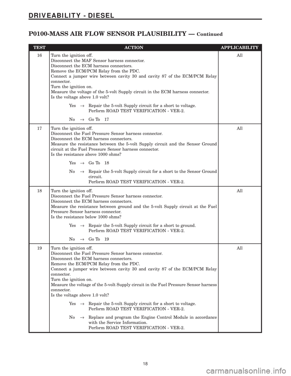
TEST ACTION APPLICABILITY
16 Turn the ignition off.
Disconnect the MAF Sensor harness connector.
Disconnect the ECM harness connectors.
Remove the ECM/PCM Relay from the PDC.
Connect a jumper wire between cavity 30 and cavity 87 of the ECM/PCM Relay
connector.
Turn the ignition on.
Measure the voltage of the 5-volt Supply circuit in the ECM harness connector.
Is the voltage above 1.0 volt?All
Ye s®Repair the 5-volt Supply circuit for a short to voltage.
Perform ROAD TEST VERIFICATION - VER-2.
No®Go To 17
17 Turn the ignition off.
Disconnect the Fuel Pressure Sensor harness connector.
Disconnect the ECM harness connectors.
Measure the resistance between the 5-volt Supply circuit and the Sensor Ground
circuit at the Fuel Pressure Sensor harness connector.
Is the resistance above 1000 ohms?All
Ye s®Go To 18
No®Repair the 5-volt Supply circuit for a short to the Sensor Ground
circuit.
Perform ROAD TEST VERIFICATION - VER-2.
18 Turn the ignition off.
Disconnect the Fuel Pressure Sensor harness connector.
Disconnect the ECM harness connectors.
Measure the resistance between ground and the 5-volt Supply circuit at the Fuel
Pressure Sensor harness connector.
Is the resistance below 1000 ohms?All
Ye s®Repair the 5-volt Supply circuit for a short to ground.
Perform ROAD TEST VERIFICATION - VER-2.
No®Go To 19
19 Turn the ignition off.
Disconnect the Fuel Pressure Sensor harness connector.
Disconnect the ECM harness connectors.
Remove the ECM/PCM Relay from the PDC.
Connect a jumper wire between cavity 30 and cavity 87 of the ECM/PCM Relay
connector.
Turn the ignition on.
Measure the voltage of the 5-volt Supply circuit in the Fuel Pressure Sensor harness
connector.
Is the voltage above 1.0 volt?All
Ye s®Repair the 5-volt Supply circuit for a short to voltage.
Perform ROAD TEST VERIFICATION - VER-2.
No®Replace and program the Engine Control Module in accordance
with the Service Information.
Perform ROAD TEST VERIFICATION - VER-2.
18
DRIVEABILITY - DIESEL
P0100-MASS AIR FLOW SENSOR PLAUSIBILITY ÐContinued
Page 1243 of 4284
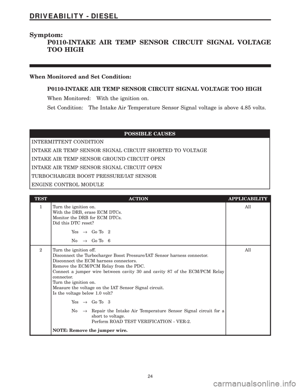
Symptom:
P0110-INTAKE AIR TEMP SENSOR CIRCUIT SIGNAL VOLTAGE
TOO HIGH
When Monitored and Set Condition:
P0110-INTAKE AIR TEMP SENSOR CIRCUIT SIGNAL VOLTAGE TOO HIGH
When Monitored: With the ignition on.
Set Condition: The Intake Air Temperature Sensor Signal voltage is above 4.85 volts.
POSSIBLE CAUSES
INTERMITTENT CONDITION
INTAKE AIR TEMP SENSOR SIGNAL CIRCUIT SHORTED TO VOLTAGE
INTAKE AIR TEMP SENSOR GROUND CIRCUIT OPEN
INTAKE AIR TEMP SENSOR SIGNAL CIRCUIT OPEN
TURBOCHARGER BOOST PRESSURE/IAT SENSOR
ENGINE CONTROL MODULE
TEST ACTION APPLICABILITY
1 Turn the ignition on.
With the DRB, erase ECM DTCs.
Monitor the DRB for ECM DTCs.
Did this DTC reset?All
Ye s®Go To 2
No®Go To 6
2 Turn the ignition off.
Disconnect the Turbocharger Boost Pressure/IAT Sensor harness connector.
Disconnect the ECM harness connectors.
Remove the ECM/PCM Relay from the PDC.
Connect a jumper wire between cavity 30 and cavity 87 of the ECM/PCM Relay
connector.
Turn the ignition on.
Measure the voltage on the IAT Sensor Signal circuit.
Is the voltage below 1.0 volt?All
Ye s®Go To 3
No®Repair the Intake Air Temperature Sensor Signal circuit for a
short to voltage.
Perform ROAD TEST VERIFICATION - VER-2.
NOTE: Remove the jumper wire.
24
DRIVEABILITY - DIESEL