2001 CHRYSLER VOYAGER frame
[x] Cancel search: framePage 3775 of 4284
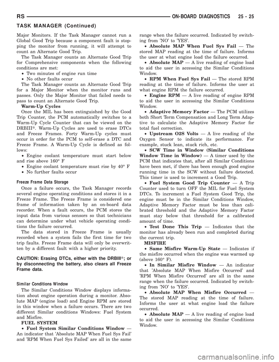
Major Monitors. If the Task Manager cannot run a
Global Good Trip because a component fault is stop-
ping the monitor from running, it will attempt to
count an Alternate Good Trip.
The Task Manager counts an Alternate Good Trip
for Comprehensive components when the following
conditions are met:
²Two minutes of engine run time
²No other faults occur
The Task Manager counts an Alternate Good Trip
for a Major Monitor when the monitor runs and
passes. Only the Major Monitor that failed needs to
pass to count an Alternate Good Trip.
Warm-Up Cycles
Once the MIL has been extinguished by the Good
Trip Counter, the PCM automatically switches to a
Warm-Up Cycle Counter that can be viewed on the
DRBIIIt. Warm-Up Cycles are used to erase DTCs
and Freeze Frames. Forty Warm-Up cycles must
occur in order for the PCM to self-erase a DTC and
Freeze Frame. A Warm-Up Cycle is defined as fol-
lows:
²Engine coolant temperature must start below
and rise above 160É F
²Engine coolant temperature must rise by 40É F
²No further faults occur
Freeze Frame Data Storage
Once a failure occurs, the Task Manager records
several engine operating conditions and stores it in a
Freeze Frame. The Freeze Frame is considered one
frame of information taken by an on-board data
recorder. When a fault occurs, the PCM stores the
input data from various sensors so that technicians
can determine under what vehicle operating condi-
tions the failure occurred.
The data stored in Freeze Frame is usually
recorded when a system fails the first time for two
trip faults. Freeze Frame data will only be overwrit-
ten by a different fault with a higher priority.
CAUTION: Erasing DTCs, either with the DRBIIIT;or
by disconnecting the battery, also clears all Freeze
Frame data.
Similar Conditions Window
The Similar Conditions Window displays informa-
tion about engine operation during a monitor. Abso-
lute MAP (engine load) and Engine RPM are stored
in this window when a failure occurs. There are two
different Similar conditions Windows: Fuel System
and Misfire.
FUEL SYSTEM
²Fuel System Similar Conditions WindowÐ
An indicator that 'Absolute MAP When Fuel Sys Fail'
and 'RPM When Fuel Sys Failed' are all in the samerange when the failure occurred. Indicated by switch-
ing from 'NO' to 'YES'.
²Absolute MAP When Fuel Sys FailÐ The
stored MAP reading at the time of failure. Informs
the user at what engine load the failure occurred.
²Absolute MAPÐ A live reading of engine load
to aid the user in accessing the Similar Conditions
Window.
²RPM When Fuel Sys FailÐ The stored RPM
reading at the time of failure. Informs the user at
what engine RPM the failure occurred.
²Engine RPMÐ A live reading of engine RPM
to aid the user in accessing the Similar Conditions
Window.
²Adaptive Memory FactorÐ The PCM utilizes
both Short Term Compensation and Long Term Adap-
tive to calculate the Adaptive Memory Factor for
total fuel correction.
²Upstream O2S VoltsÐ A live reading of the
Oxygen Sensor to indicate its performance. For
example, stuck lean, stuck rich, etc.
²SCW Time in Window (Similar Conditions
Window Time in Window)Ð A timer used by the
PCM that indicates that, after all Similar Conditions
have been met, if there has been enough good engine
running time in the SCW without failure detected.
This timer is used to increment a Good Trip.
²Fuel System Good Trip CounterÐATrip
Counter used to turn OFF the MIL for Fuel System
DTCs. To increment a Fuel System Good Trip, the
engine must be in the Similar Conditions Window,
Adaptive Memory Factor must be less than cali-
brated threshold and the Adaptive Memory Factor
must stay below that threshold for a calibrated
amount of time.
²Test Done This TripÐ Indicates that the
monitor has already been run and completed during
the current trip.
MISFIRE
²Same Misfire Warm-Up StateÐ Indicates if
the misfire occurred when the engine was warmed up
(above 160É F).
²In Similar Misfire WindowÐ An indicator
that 'Absolute MAP When Misfire Occurred' and
'RPM When Misfire Occurred' are all in the same
range when the failure occurred. Indicated by switch-
ing from 'NO' to 'YES'.
²Absolute MAP When Misfire OccurredÐ
The stored MAP reading at the time of failure.
Informs the user at what engine load the failure
occurred.
²Absolute MAPÐ A live reading of engine load
to aid the user in accessing the Similar Conditions
Window.
RSON-BOARD DIAGNOSTICS25-25
TASK MANAGER (Continued)
Page 3813 of 4284
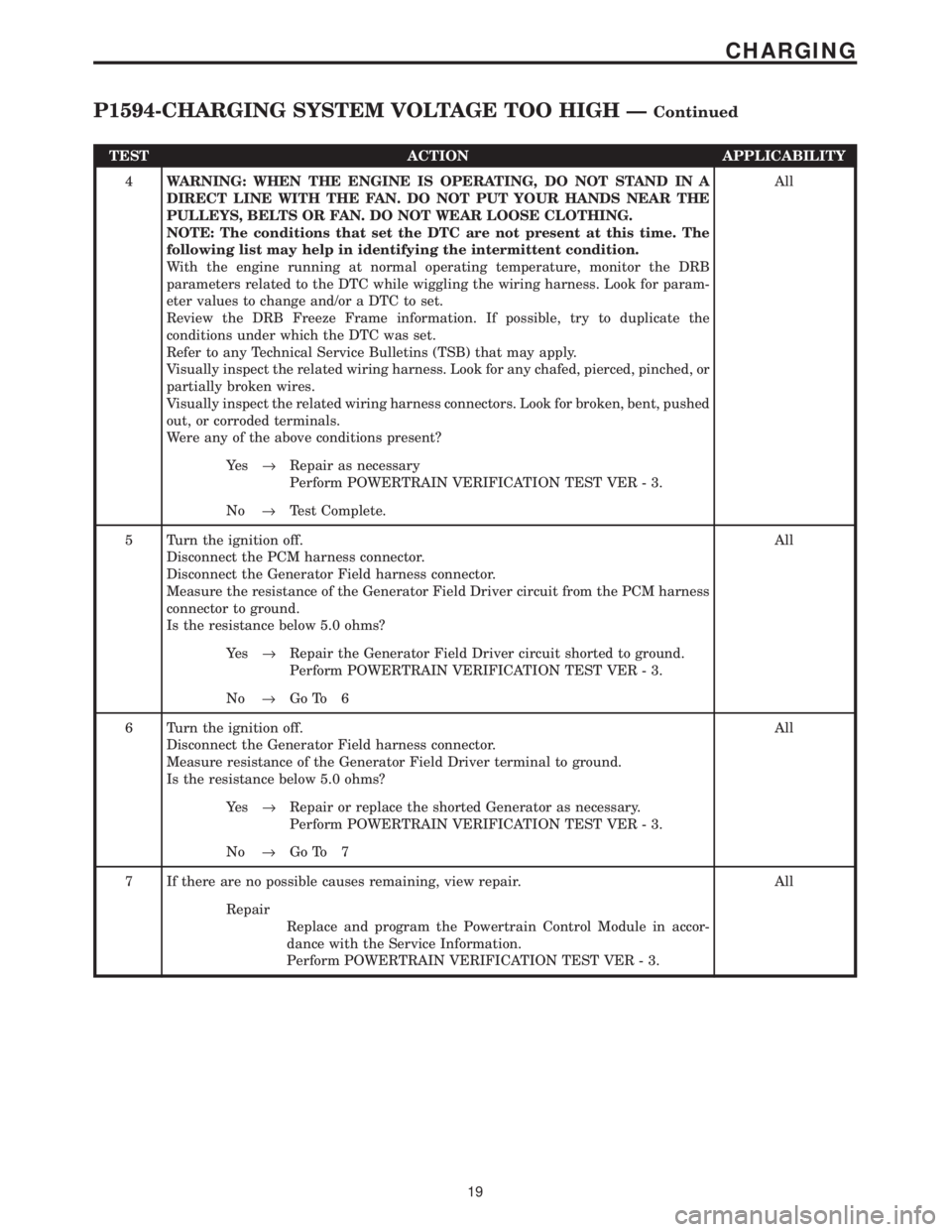
TEST ACTION APPLICABILITY
4WARNING: WHEN THE ENGINE IS OPERATING, DO NOT STAND IN A
DIRECT LINE WITH THE FAN. DO NOT PUT YOUR HANDS NEAR THE
PULLEYS, BELTS OR FAN. DO NOT WEAR LOOSE CLOTHING.
NOTE: The conditions that set the DTC are not present at this time. The
following list may help in identifying the intermittent condition.
With the engine running at normal operating temperature, monitor the DRB
parameters related to the DTC while wiggling the wiring harness. Look for param-
eter values to change and/or a DTC to set.
Review the DRB Freeze Frame information. If possible, try to duplicate the
conditions under which the DTC was set.
Refer to any Technical Service Bulletins (TSB) that may apply.
Visually inspect the related wiring harness. Look for any chafed, pierced, pinched, or
partially broken wires.
Visually inspect the related wiring harness connectors. Look for broken, bent, pushed
out, or corroded terminals.
Were any of the above conditions present?All
Ye s®Repair as necessary
Perform POWERTRAIN VERIFICATION TEST VER - 3.
No®Test Complete.
5 Turn the ignition off.
Disconnect the PCM harness connector.
Disconnect the Generator Field harness connector.
Measure the resistance of the Generator Field Driver circuit from the PCM harness
connector to ground.
Is the resistance below 5.0 ohms?All
Ye s®Repair the Generator Field Driver circuit shorted to ground.
Perform POWERTRAIN VERIFICATION TEST VER - 3.
No®Go To 6
6 Turn the ignition off.
Disconnect the Generator Field harness connector.
Measure resistance of the Generator Field Driver terminal to ground.
Is the resistance below 5.0 ohms?All
Ye s®Repair or replace the shorted Generator as necessary.
Perform POWERTRAIN VERIFICATION TEST VER - 3.
No®Go To 7
7 If there are no possible causes remaining, view repair. All
Repair
Replace and program the Powertrain Control Module in accor-
dance with the Service Information.
Perform POWERTRAIN VERIFICATION TEST VER - 3.
19
CHARGING
P1594-CHARGING SYSTEM VOLTAGE TOO HIGH ÐContinued
Page 3816 of 4284
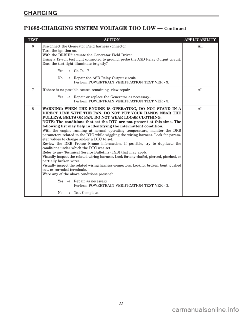
TEST ACTION APPLICABILITY
6 Disconnect the Generator Field harness connector.
Turn the ignition on.
With the DRBIIItactuate the Generator Field Driver.
Using a 12-volt test light connected to ground, probe the ASD Relay Output circuit.
Does the test light illuminate brightly?All
Ye s®Go To 7
No®Repair the ASD Relay Output circuit.
Perform POWERTRAIN VERIFICATION TEST VER - 3.
7 If there is no possible causes remaining, view repair. All
Ye s®Repair or replace the Generator as necessary..
Perform POWERTRAIN VERIFICATION TEST VER - 3.
8WARNING: WHEN THE ENGINE IS OPERATING, DO NOT STAND IN A
DIRECT LINE WITH THE FAN. DO NOT PUT YOUR HANDS NEAR THE
PULLEYS, BELTS OR FAN. DO NOT WEAR LOOSE CLOTHING.
NOTE: The conditions that set the DTC are not present at this time. The
following list may help in identifying the intermittent condition.
With the engine running at normal operating temperature, monitor the DRB
parameters related to the DTC while wiggling the wiring harness. Look for param-
eter values to change and/or a DTC to set.
Review the DRB Freeze Frame information. If possible, try to duplicate the
conditions under which the DTC was set.
Refer to any Technical Service Bulletins (TSB) that may apply.
Visually inspect the related wiring harness. Look for any chafed, pierced, pinched, or
partially broken wires.
Visually inspect the related wiring harness connectors. Look for broken, bent, pushed
out, or corroded terminals.
Were any of the above conditions present?All
Ye s®Repair as necessary
Perform POWERTRAIN VERIFICATION TEST VER - 3.
No®Test Complete.
22
CHARGING
P1682-CHARGING SYSTEM VOLTAGE TOO LOW ÐContinued
Page 3823 of 4284
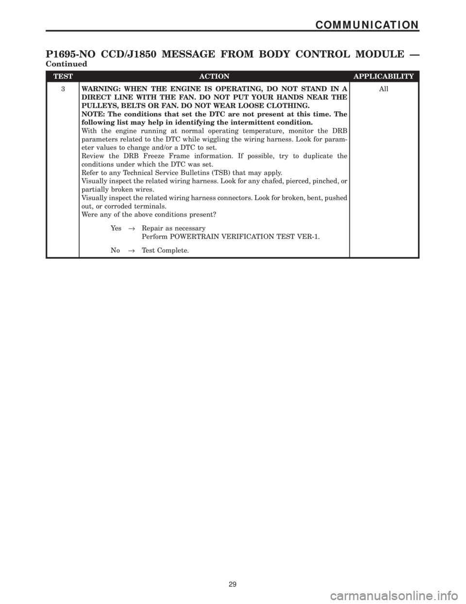
TEST ACTION APPLICABILITY
3WARNING: WHEN THE ENGINE IS OPERATING, DO NOT STAND IN A
DIRECT LINE WITH THE FAN. DO NOT PUT YOUR HANDS NEAR THE
PULLEYS, BELTS OR FAN. DO NOT WEAR LOOSE CLOTHING.
NOTE: The conditions that set the DTC are not present at this time. The
following list may help in identifying the intermittent condition.
With the engine running at normal operating temperature, monitor the DRB
parameters related to the DTC while wiggling the wiring harness. Look for param-
eter values to change and/or a DTC to set.
Review the DRB Freeze Frame information. If possible, try to duplicate the
conditions under which the DTC was set.
Refer to any Technical Service Bulletins (TSB) that may apply.
Visually inspect the related wiring harness. Look for any chafed, pierced, pinched, or
partially broken wires.
Visually inspect the related wiring harness connectors. Look for broken, bent, pushed
out, or corroded terminals.
Were any of the above conditions present?All
Ye s®Repair as necessary
Perform POWERTRAIN VERIFICATION TEST VER-1.
No®Test Complete.
29
COMMUNICATION
P1695-NO CCD/J1850 MESSAGE FROM BODY CONTROL MODULE Ð
Continued
Page 3827 of 4284
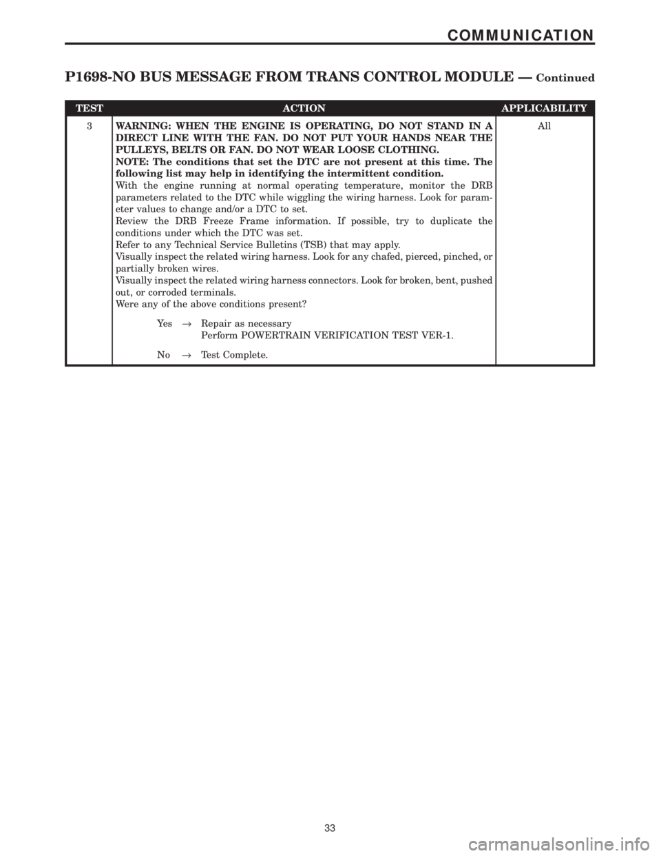
TEST ACTION APPLICABILITY
3WARNING: WHEN THE ENGINE IS OPERATING, DO NOT STAND IN A
DIRECT LINE WITH THE FAN. DO NOT PUT YOUR HANDS NEAR THE
PULLEYS, BELTS OR FAN. DO NOT WEAR LOOSE CLOTHING.
NOTE: The conditions that set the DTC are not present at this time. The
following list may help in identifying the intermittent condition.
With the engine running at normal operating temperature, monitor the DRB
parameters related to the DTC while wiggling the wiring harness. Look for param-
eter values to change and/or a DTC to set.
Review the DRB Freeze Frame information. If possible, try to duplicate the
conditions under which the DTC was set.
Refer to any Technical Service Bulletins (TSB) that may apply.
Visually inspect the related wiring harness. Look for any chafed, pierced, pinched, or
partially broken wires.
Visually inspect the related wiring harness connectors. Look for broken, bent, pushed
out, or corroded terminals.
Were any of the above conditions present?All
Ye s®Repair as necessary
Perform POWERTRAIN VERIFICATION TEST VER-1.
No®Test Complete.
33
COMMUNICATION
P1698-NO BUS MESSAGE FROM TRANS CONTROL MODULE ÐContinued
Page 3838 of 4284
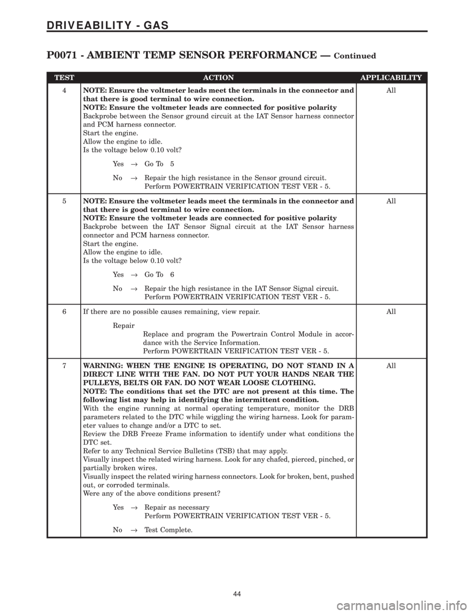
TEST ACTION APPLICABILITY
4NOTE: Ensure the voltmeter leads meet the terminals in the connector and
that there is good terminal to wire connection.
NOTE: Ensure the voltmeter leads are connected for positive polarity
Backprobe between the Sensor ground circuit at the IAT Sensor harness connector
and PCM harness connector.
Start the engine.
Allow the engine to idle.
Is the voltage below 0.10 volt?All
Ye s®Go To 5
No®Repair the high resistance in the Sensor ground circuit.
Perform POWERTRAIN VERIFICATION TEST VER - 5.
5NOTE: Ensure the voltmeter leads meet the terminals in the connector and
that there is good terminal to wire connection.
NOTE: Ensure the voltmeter leads are connected for positive polarity
Backprobe between the IAT Sensor Signal circuit at the IAT Sensor harness
connector and PCM harness connector.
Start the engine.
Allow the engine to idle.
Is the voltage below 0.10 volt?All
Ye s®Go To 6
No®Repair the high resistance in the IAT Sensor Signal circuit.
Perform POWERTRAIN VERIFICATION TEST VER - 5.
6 If there are no possible causes remaining, view repair. All
Repair
Replace and program the Powertrain Control Module in accor-
dance with the Service Information.
Perform POWERTRAIN VERIFICATION TEST VER - 5.
7WARNING: WHEN THE ENGINE IS OPERATING, DO NOT STAND IN A
DIRECT LINE WITH THE FAN. DO NOT PUT YOUR HANDS NEAR THE
PULLEYS, BELTS OR FAN. DO NOT WEAR LOOSE CLOTHING.
NOTE: The conditions that set the DTC are not present at this time. The
following list may help in identifying the intermittent condition.
With the engine running at normal operating temperature, monitor the DRB
parameters related to the DTC while wiggling the wiring harness. Look for param-
eter values to change and/or a DTC to set.
Review the DRB Freeze Frame information to identify under what conditions the
DTC set.
Refer to any Technical Service Bulletins (TSB) that may apply.
Visually inspect the related wiring harness. Look for any chafed, pierced, pinched, or
partially broken wires.
Visually inspect the related wiring harness connectors. Look for broken, bent, pushed
out, or corroded terminals.
Were any of the above conditions present?All
Ye s®Repair as necessary
Perform POWERTRAIN VERIFICATION TEST VER - 5.
No®Test Complete.
44
DRIVEABILITY - GAS
P0071 - AMBIENT TEMP SENSOR PERFORMANCE ÐContinued
Page 3841 of 4284
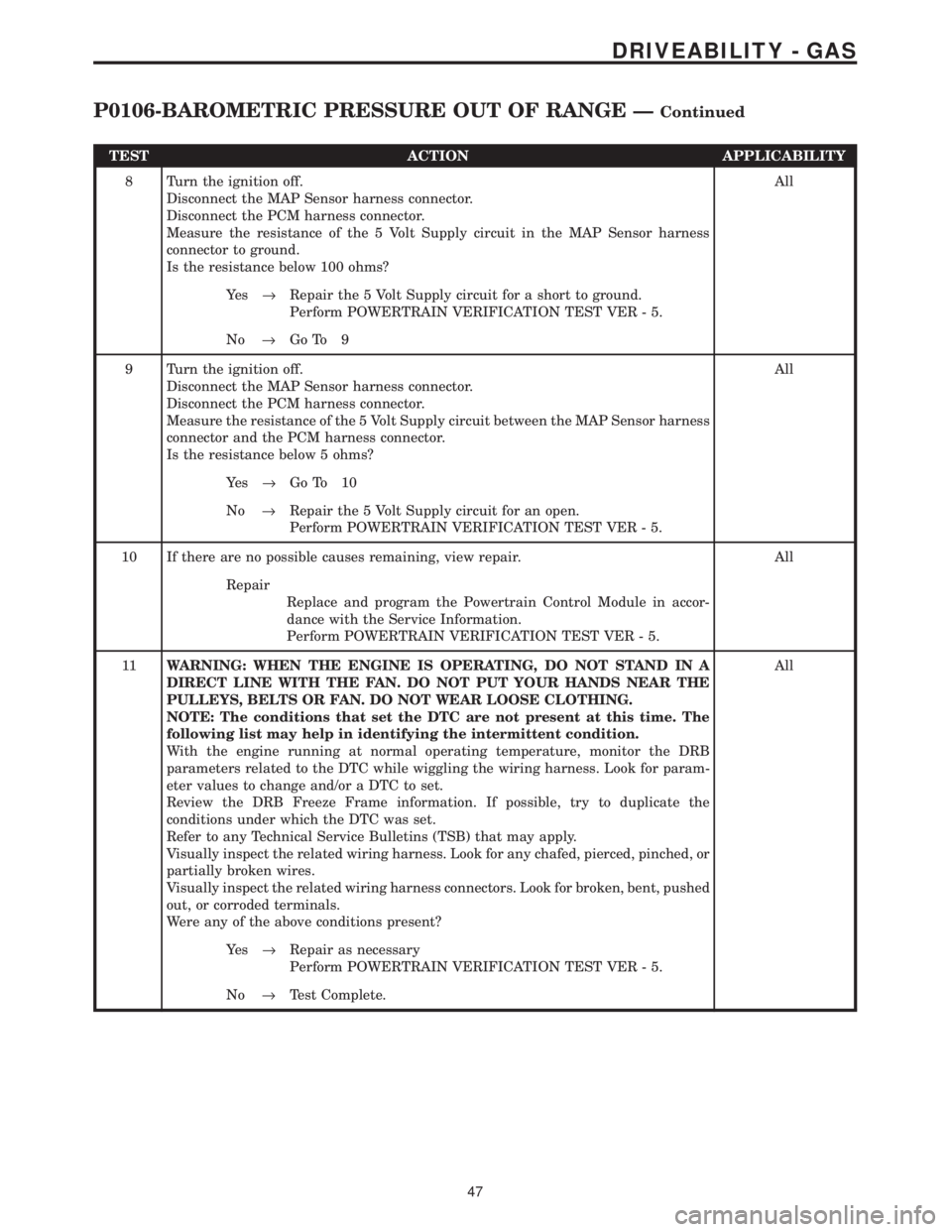
TEST ACTION APPLICABILITY
8 Turn the ignition off.
Disconnect the MAP Sensor harness connector.
Disconnect the PCM harness connector.
Measure the resistance of the 5 Volt Supply circuit in the MAP Sensor harness
connector to ground.
Is the resistance below 100 ohms?All
Ye s®Repair the 5 Volt Supply circuit for a short to ground.
Perform POWERTRAIN VERIFICATION TEST VER - 5.
No®Go To 9
9 Turn the ignition off.
Disconnect the MAP Sensor harness connector.
Disconnect the PCM harness connector.
Measure the resistance of the 5 Volt Supply circuit between the MAP Sensor harness
connector and the PCM harness connector.
Is the resistance below 5 ohms?All
Ye s®Go To 10
No®Repair the 5 Volt Supply circuit for an open.
Perform POWERTRAIN VERIFICATION TEST VER - 5.
10 If there are no possible causes remaining, view repair. All
Repair
Replace and program the Powertrain Control Module in accor-
dance with the Service Information.
Perform POWERTRAIN VERIFICATION TEST VER - 5.
11WARNING: WHEN THE ENGINE IS OPERATING, DO NOT STAND IN A
DIRECT LINE WITH THE FAN. DO NOT PUT YOUR HANDS NEAR THE
PULLEYS, BELTS OR FAN. DO NOT WEAR LOOSE CLOTHING.
NOTE: The conditions that set the DTC are not present at this time. The
following list may help in identifying the intermittent condition.
With the engine running at normal operating temperature, monitor the DRB
parameters related to the DTC while wiggling the wiring harness. Look for param-
eter values to change and/or a DTC to set.
Review the DRB Freeze Frame information. If possible, try to duplicate the
conditions under which the DTC was set.
Refer to any Technical Service Bulletins (TSB) that may apply.
Visually inspect the related wiring harness. Look for any chafed, pierced, pinched, or
partially broken wires.
Visually inspect the related wiring harness connectors. Look for broken, bent, pushed
out, or corroded terminals.
Were any of the above conditions present?All
Ye s®Repair as necessary
Perform POWERTRAIN VERIFICATION TEST VER - 5.
No®Test Complete.
47
DRIVEABILITY - GAS
P0106-BAROMETRIC PRESSURE OUT OF RANGE ÐContinued
Page 3844 of 4284
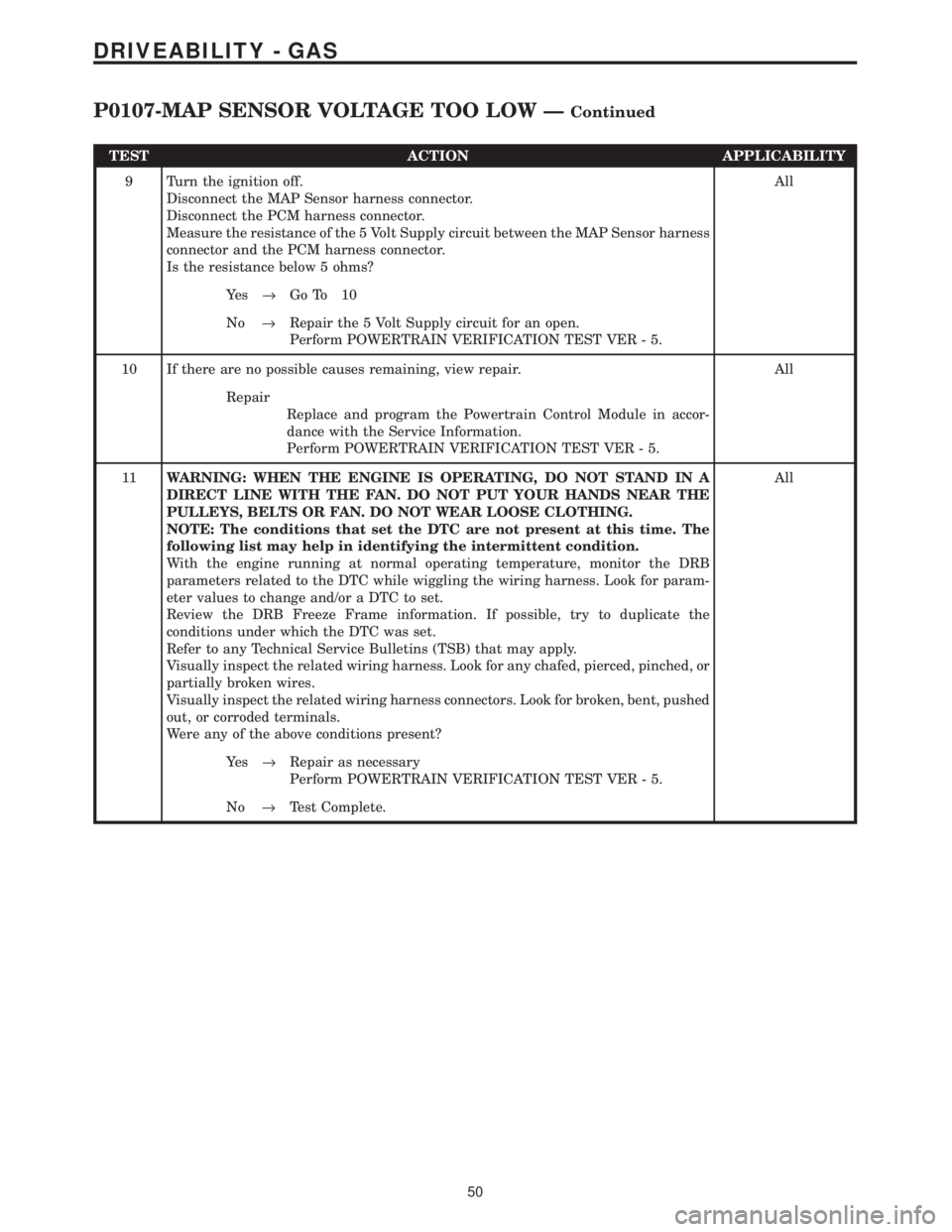
TEST ACTION APPLICABILITY
9 Turn the ignition off.
Disconnect the MAP Sensor harness connector.
Disconnect the PCM harness connector.
Measure the resistance of the 5 Volt Supply circuit between the MAP Sensor harness
connector and the PCM harness connector.
Is the resistance below 5 ohms?All
Ye s®Go To 10
No®Repair the 5 Volt Supply circuit for an open.
Perform POWERTRAIN VERIFICATION TEST VER - 5.
10 If there are no possible causes remaining, view repair. All
Repair
Replace and program the Powertrain Control Module in accor-
dance with the Service Information.
Perform POWERTRAIN VERIFICATION TEST VER - 5.
11WARNING: WHEN THE ENGINE IS OPERATING, DO NOT STAND IN A
DIRECT LINE WITH THE FAN. DO NOT PUT YOUR HANDS NEAR THE
PULLEYS, BELTS OR FAN. DO NOT WEAR LOOSE CLOTHING.
NOTE: The conditions that set the DTC are not present at this time. The
following list may help in identifying the intermittent condition.
With the engine running at normal operating temperature, monitor the DRB
parameters related to the DTC while wiggling the wiring harness. Look for param-
eter values to change and/or a DTC to set.
Review the DRB Freeze Frame information. If possible, try to duplicate the
conditions under which the DTC was set.
Refer to any Technical Service Bulletins (TSB) that may apply.
Visually inspect the related wiring harness. Look for any chafed, pierced, pinched, or
partially broken wires.
Visually inspect the related wiring harness connectors. Look for broken, bent, pushed
out, or corroded terminals.
Were any of the above conditions present?All
Ye s®Repair as necessary
Perform POWERTRAIN VERIFICATION TEST VER - 5.
No®Test Complete.
50
DRIVEABILITY - GAS
P0107-MAP SENSOR VOLTAGE TOO LOW ÐContinued