Page 1002 of 4284
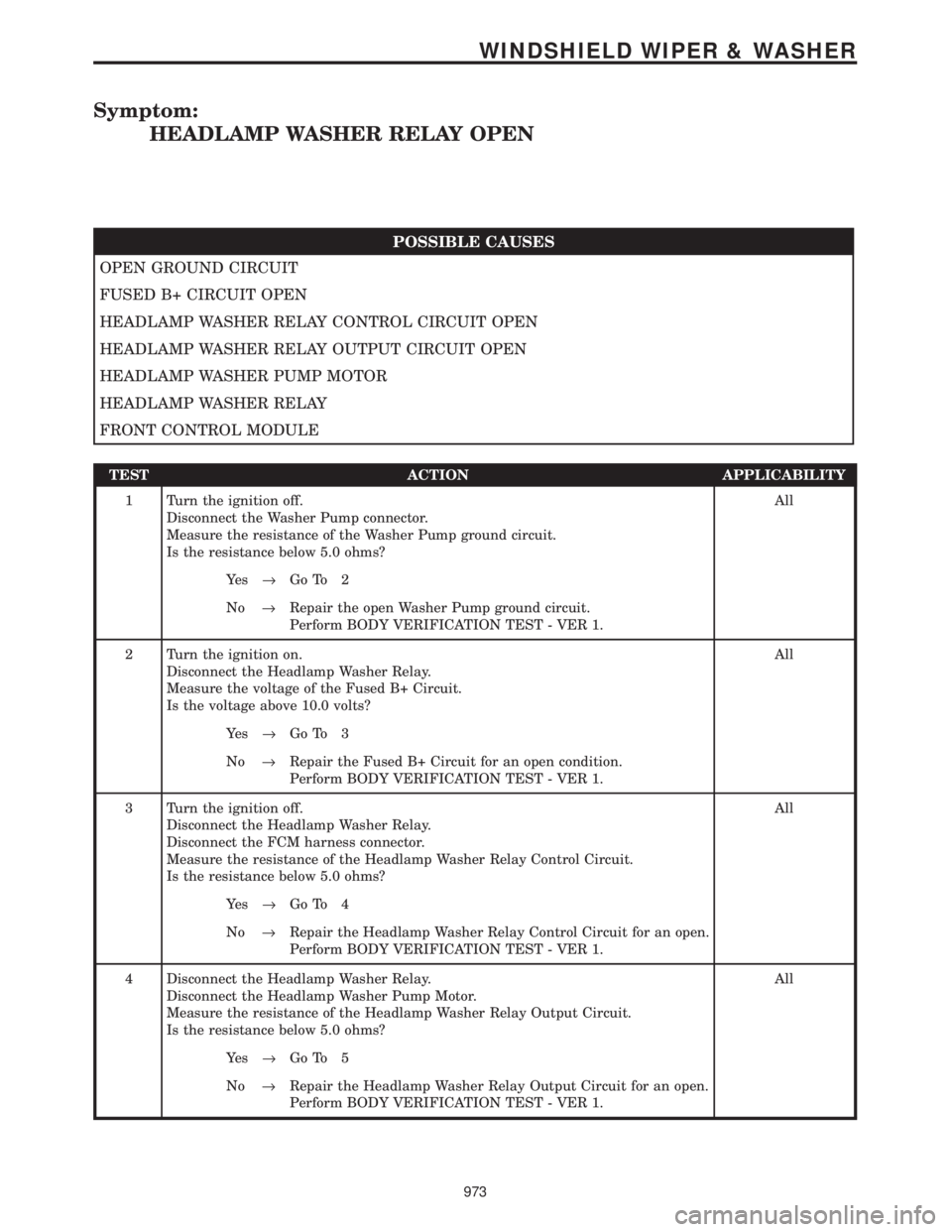
Symptom:
HEADLAMP WASHER RELAY OPEN
POSSIBLE CAUSES
OPEN GROUND CIRCUIT
FUSED B+ CIRCUIT OPEN
HEADLAMP WASHER RELAY CONTROL CIRCUIT OPEN
HEADLAMP WASHER RELAY OUTPUT CIRCUIT OPEN
HEADLAMP WASHER PUMP MOTOR
HEADLAMP WASHER RELAY
FRONT CONTROL MODULE
TEST ACTION APPLICABILITY
1 Turn the ignition off.
Disconnect the Washer Pump connector.
Measure the resistance of the Washer Pump ground circuit.
Is the resistance below 5.0 ohms?All
Ye s®Go To 2
No®Repair the open Washer Pump ground circuit.
Perform BODY VERIFICATION TEST - VER 1.
2 Turn the ignition on.
Disconnect the Headlamp Washer Relay.
Measure the voltage of the Fused B+ Circuit.
Is the voltage above 10.0 volts?All
Ye s®Go To 3
No®Repair the Fused B+ Circuit for an open condition.
Perform BODY VERIFICATION TEST - VER 1.
3 Turn the ignition off.
Disconnect the Headlamp Washer Relay.
Disconnect the FCM harness connector.
Measure the resistance of the Headlamp Washer Relay Control Circuit.
Is the resistance below 5.0 ohms?All
Ye s®Go To 4
No®Repair the Headlamp Washer Relay Control Circuit for an open.
Perform BODY VERIFICATION TEST - VER 1.
4 Disconnect the Headlamp Washer Relay.
Disconnect the Headlamp Washer Pump Motor.
Measure the resistance of the Headlamp Washer Relay Output Circuit.
Is the resistance below 5.0 ohms?All
Ye s®Go To 5
No®Repair the Headlamp Washer Relay Output Circuit for an open.
Perform BODY VERIFICATION TEST - VER 1.
973
WINDSHIELD WIPER & WASHER
Page 1004 of 4284
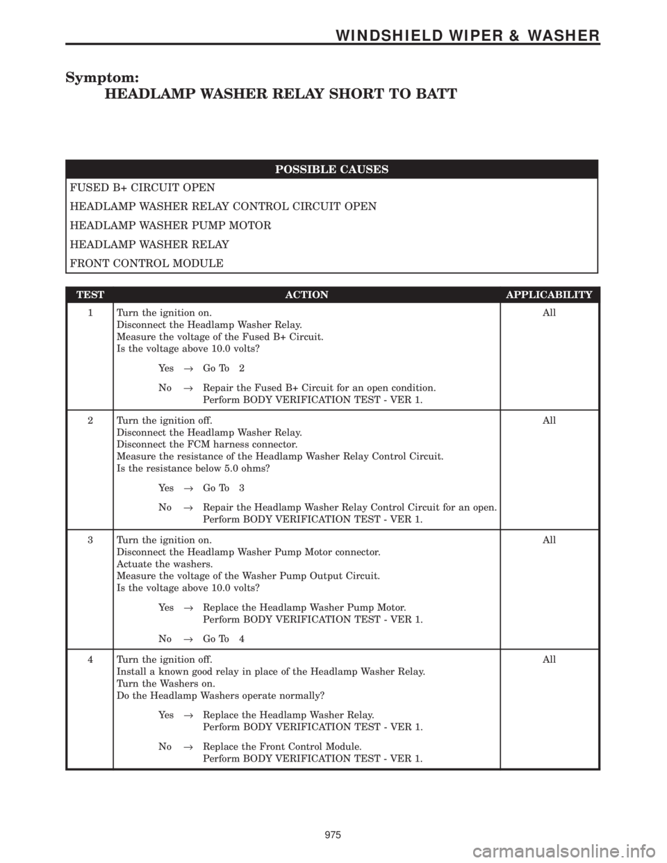
Symptom:
HEADLAMP WASHER RELAY SHORT TO BATT
POSSIBLE CAUSES
FUSED B+ CIRCUIT OPEN
HEADLAMP WASHER RELAY CONTROL CIRCUIT OPEN
HEADLAMP WASHER PUMP MOTOR
HEADLAMP WASHER RELAY
FRONT CONTROL MODULE
TEST ACTION APPLICABILITY
1 Turn the ignition on.
Disconnect the Headlamp Washer Relay.
Measure the voltage of the Fused B+ Circuit.
Is the voltage above 10.0 volts?All
Ye s®Go To 2
No®Repair the Fused B+ Circuit for an open condition.
Perform BODY VERIFICATION TEST - VER 1.
2 Turn the ignition off.
Disconnect the Headlamp Washer Relay.
Disconnect the FCM harness connector.
Measure the resistance of the Headlamp Washer Relay Control Circuit.
Is the resistance below 5.0 ohms?All
Ye s®Go To 3
No®Repair the Headlamp Washer Relay Control Circuit for an open.
Perform BODY VERIFICATION TEST - VER 1.
3 Turn the ignition on.
Disconnect the Headlamp Washer Pump Motor connector.
Actuate the washers.
Measure the voltage of the Washer Pump Output Circuit.
Is the voltage above 10.0 volts?All
Ye s®Replace the Headlamp Washer Pump Motor.
Perform BODY VERIFICATION TEST - VER 1.
No®Go To 4
4 Turn the ignition off.
Install a known good relay in place of the Headlamp Washer Relay.
Turn the Washers on.
Do the Headlamp Washers operate normally?All
Ye s®Replace the Headlamp Washer Relay.
Perform BODY VERIFICATION TEST - VER 1.
No®Replace the Front Control Module.
Perform BODY VERIFICATION TEST - VER 1.
975
WINDSHIELD WIPER & WASHER
Page 1007 of 4284
Symptom:
REAR WASHER OUTPUT OPEN
When Monitored and Set Condition:
REAR WASHER OUTPUT OPEN
When Monitored: Ignition on.
Set Condition:
POSSIBLE CAUSES
INTERMITTENT WIRING AND CONNECTORS
FUSED ACCESSORY RELAY OUTPUT CIRCUIT
REAR WASHER MOTOR CONTROL CIRCUIT OPEN
REAR WASHER MOTOR CONTROL CIRCUIT SHORT TO VOLTAGE
REAR WASHER PUMP MOTOR
FRONT CONTROL MODULE
TEST ACTION APPLICABILITY
1 Ignition on, engine not running.
Press the Rear Washer Switch.
Does the Rear Washer Motor Function?All
Ye s®Go To 2
No®Go To 3
2 Turn the ignition on.
With the DRBIIIt, erase all BCM and FCM DTCs.
Turn the ignition off.
The conditions necessary to set this DTC are not present at this time.
Using the schematics as a guide, inspect the wiring and connectors specific to this
circuit.
Wiggle the wiring while checking for shorts and open circuits.
Were there any problems found?All
Ye s®Repair as necessary.
Perform BODY VERIFICATION TEST - VER 1.
No®Test Complete.
978
WINDSHIELD WIPER & WASHER
Page 1008 of 4284
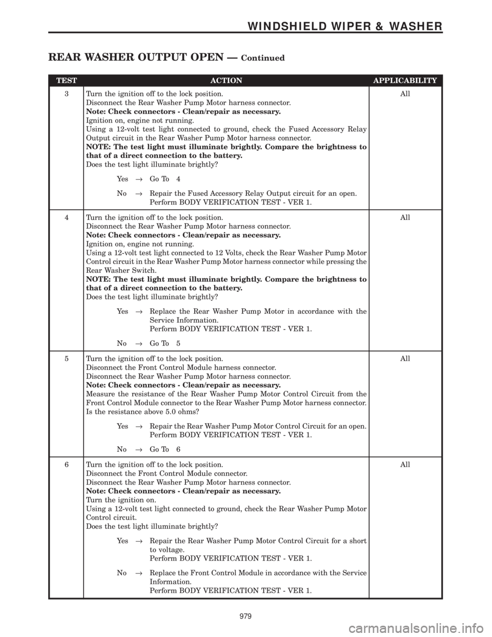
TEST ACTION APPLICABILITY
3 Turn the ignition off to the lock position.
Disconnect the Rear Washer Pump Motor harness connector.
Note: Check connectors - Clean/repair as necessary.
Ignition on, engine not running.
Using a 12-volt test light connected to ground, check the Fused Accessory Relay
Output circuit in the Rear Washer Pump Motor harness connector.
NOTE: The test light must illuminate brightly. Compare the brightness to
that of a direct connection to the battery.
Does the test light illuminate brightly?All
Ye s®Go To 4
No®Repair the Fused Accessory Relay Output circuit for an open.
Perform BODY VERIFICATION TEST - VER 1.
4 Turn the ignition off to the lock position.
Disconnect the Rear Washer Pump Motor harness connector.
Note: Check connectors - Clean/repair as necessary.
Ignition on, engine not running.
Using a 12-volt test light connected to 12 Volts, check the Rear Washer Pump Motor
Control circuit in the Rear Washer Pump Motor harness connector while pressing the
Rear Washer Switch.
NOTE: The test light must illuminate brightly. Compare the brightness to
that of a direct connection to the battery.
Does the test light illuminate brightly?All
Ye s®Replace the Rear Washer Pump Motor in accordance with the
Service Information.
Perform BODY VERIFICATION TEST - VER 1.
No®Go To 5
5 Turn the ignition off to the lock position.
Disconnect the Front Control Module harness connector.
Disconnect the Rear Washer Pump Motor harness connector.
Note: Check connectors - Clean/repair as necessary.
Measure the resistance of the Rear Washer Pump Motor Control Circuit from the
Front Control Module connector to the Rear Washer Pump Motor harness connector.
Is the resistance above 5.0 ohms?All
Ye s®Repair the Rear Washer Pump Motor Control Circuit for an open.
Perform BODY VERIFICATION TEST - VER 1.
No®Go To 6
6 Turn the ignition off to the lock position.
Disconnect the Front Control Module connector.
Disconnect the Rear Washer Pump Motor harness connector.
Note: Check connectors - Clean/repair as necessary.
Turn the ignition on.
Using a 12-volt test light connected to ground, check the Rear Washer Pump Motor
Control circuit.
Does the test light illuminate brightly?All
Ye s®Repair the Rear Washer Pump Motor Control Circuit for a short
to voltage.
Perform BODY VERIFICATION TEST - VER 1.
No®Replace the Front Control Module in accordance with the Service
Information.
Perform BODY VERIFICATION TEST - VER 1.
979
WINDSHIELD WIPER & WASHER
REAR WASHER OUTPUT OPEN ÐContinued
Page 1012 of 4284
TEST ACTION APPLICABILITY
4 Turn the ignition off to the lock position.
Disconnect the Body Control Module harness connector.
Connect a 20A Fused jumper wire between B+ and the Rear Wiper Motor Signal
circuit in the Body Control Module connector harness.
NOTE: An internal short in the Wiper Motor may cause the fuse to open.
Does the Wiper Motor function?All
Ye s®Replace the Body Control Module in accordance with the Service
Information.
Perform BODY VERIFICATION TEST - VER 1.
No®Replace the Rear Wiper Motor in accordance with the Service
Information.
Perform BODY VERIFICATION TEST - VER 1.
983
WINDSHIELD WIPER & WASHER
REAR WIPER OUTPUT SHORT TO GROUND ÐContinued
Page 1041 of 4284
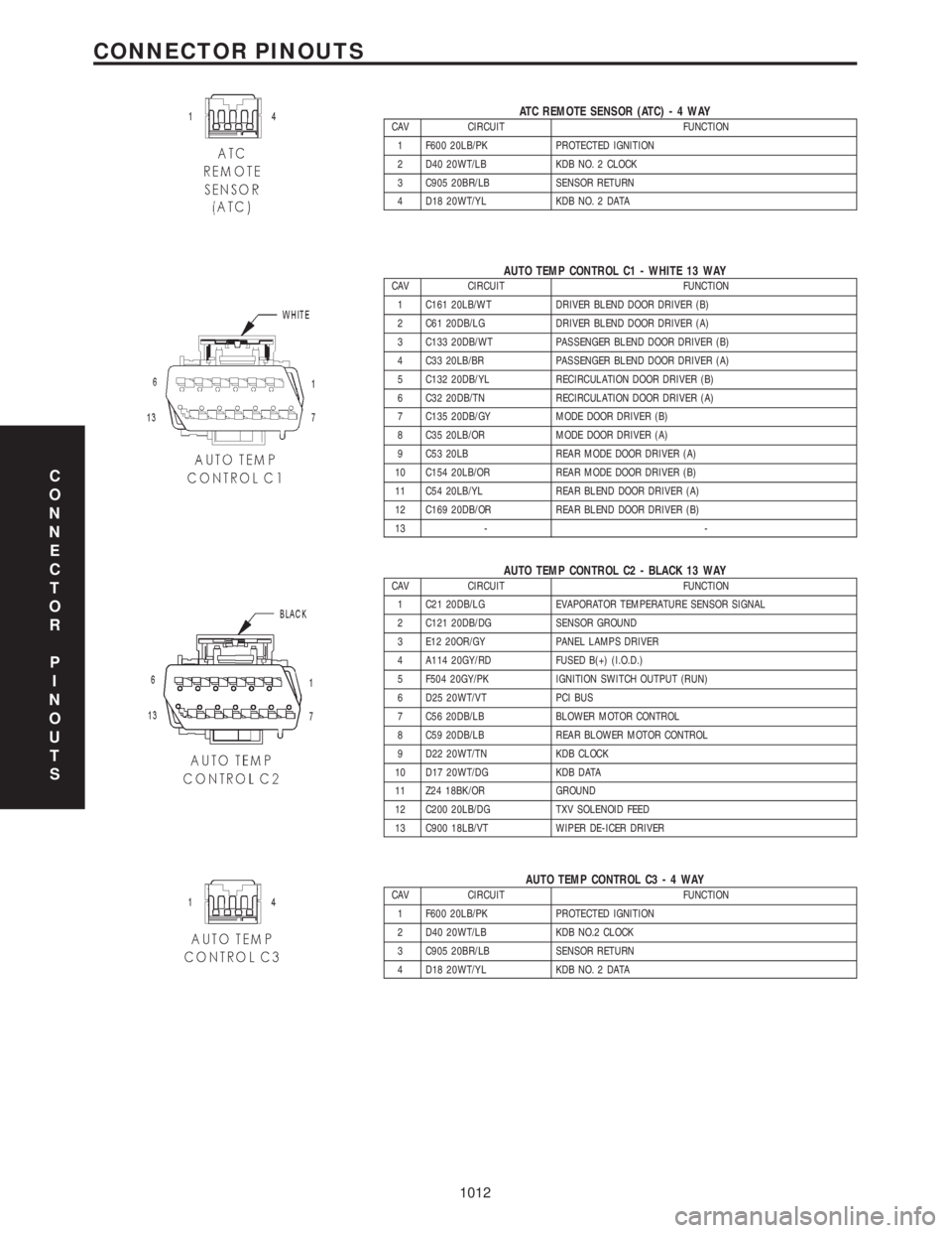
ATC REMOTE SENSOR (ATC)-4WAYCAV CIRCUIT FUNCTION
1 F600 20LB/PK PROTECTED IGNITION
2 D40 20WT/LB KDB NO. 2 CLOCK
3 C905 20BR/LB SENSOR RETURN
4 D18 20WT/YL KDB NO. 2 DATA
AUTO TEMP CONTROL C1 - WHITE 13 WAYCAV CIRCUIT FUNCTION
1 C161 20LB/WT DRIVER BLEND DOOR DRIVER (B)
2 C61 20DB/LG DRIVER BLEND DOOR DRIVER (A)
3 C133 20DB/WT PASSENGER BLEND DOOR DRIVER (B)
4 C33 20LB/BR PASSENGER BLEND DOOR DRIVER (A)
5 C132 20DB/YL RECIRCULATION DOOR DRIVER (B)
6 C32 20DB/TN RECIRCULATION DOOR DRIVER (A)
7 C135 20DB/GY MODE DOOR DRIVER (B)
8 C35 20LB/OR MODE DOOR DRIVER (A)
9 C53 20LB REAR MODE DOOR DRIVER (A)
10 C154 20LB/OR REAR MODE DOOR DRIVER (B)
11 C54 20LB/YL REAR BLEND DOOR DRIVER (A)
12 C169 20DB/OR REAR BLEND DOOR DRIVER (B)
13 - -
AUTO TEMP CONTROL C2 - BLACK 13 WAYCAV CIRCUIT FUNCTION
1 C21 20DB/LG EVAPORATOR TEMPERATURE SENSOR SIGNAL
2 C121 20DB/DG SENSOR GROUND
3 E12 20OR/GY PANEL LAMPS DRIVER
4 A114 20GY/RD FUSED B(+) (I.O.D.)
5 F504 20GY/PK IGNITION SWITCH OUTPUT (RUN)
6 D25 20WT/VT PCI BUS
7 C56 20DB/LB BLOWER MOTOR CONTROL
8 C59 20DB/LB REAR BLOWER MOTOR CONTROL
9 D22 20WT/TN KDB CLOCK
10 D17 20WT/DG KDB DATA
11 Z24 18BK/OR GROUND
12 C200 20LB/DG TXV SOLENOID FEED
13 C900 18LB/VT WIPER DE-ICER DRIVER
AUTO TEMP CONTROL C3-4WAYCAV CIRCUIT FUNCTION
1 F600 20LB/PK PROTECTED IGNITION
2 D40 20WT/LB KDB NO.2 CLOCK
3 C905 20BR/LB SENSOR RETURN
4 D18 20WT/YL KDB NO. 2 DATA
C
O
N
N
E
C
T
O
R
P
I
N
O
U
T
S
1012
CONNECTOR PINOUTS
Page 1042 of 4284
BLOWER MOTOR RESISTOR C1 (MTC) - BLACK 6 WAYCAV CIRCUIT FUNCTION
1 C75 12DB/GY BLOWER MOTOR HIGH DRIVER
2 C74 12DB/WT BLOWER MOTOR M3 DRIVER
3 C73 14DB/VT BLOWER MOTOR M2 DRIVER
4 C7 12DB FUSED FRONT BLOWER MOTOR RELAY OUTPUT
5 C72 16DB/OR BLOWER MOTOR M1 DRIVER
6 C71 16DB/BR BLOWER MOTOR LOW DRIVER
BLOWER MOTOR RESISTOR C2 (MTC) - BLACK 2 WAYCAV CIRCUIT FUNCTION
1 C70 12DG REAR BLOWER HIGH SPEED
2 C7 12BK HIGH SPEED BLOWER MOTOR
BODY CONTROL MODULE C1 - BLACK/BLACK 6 WAYCAV CIRCUIT FUNCTION
1 A102 12WT/RD FUSED B(+)
2 A701 16BR/RD FUSED B(+) (HAZARD)
3 Z100 12BK/TN GROUND
4- -
5 A101 12VT/RD FUSED B(+)
6- -
C
O
N
N
E
C
T
O
R
P
I
N
O
U
T
S
1013
CONNECTOR PINOUTS
Page 1043 of 4284
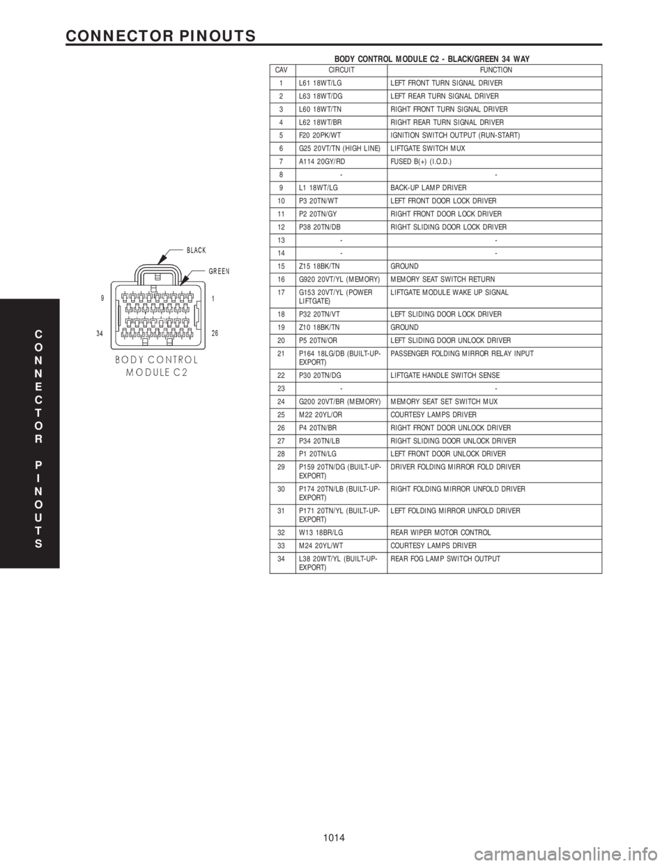
BODY CONTROL MODULE C2 - BLACK/GREEN 34 WAYCAV CIRCUIT FUNCTION
1 L61 18WT/LG LEFT FRONT TURN SIGNAL DRIVER
2 L63 18WT/DG LEFT REAR TURN SIGNAL DRIVER
3 L60 18WT/TN RIGHT FRONT TURN SIGNAL DRIVER
4 L62 18WT/BR RIGHT REAR TURN SIGNAL DRIVER
5 F20 20PK/WT IGNITION SWITCH OUTPUT (RUN-START)
6 G25 20VT/TN (HIGH LINE) LIFTGATE SWITCH MUX
7 A114 20GY/RD FUSED B(+) (I.O.D.)
8- -
9 L1 18WT/LG BACK-UP LAMP DRIVER
10 P3 20TN/WT LEFT FRONT DOOR LOCK DRIVER
11 P2 20TN/GY RIGHT FRONT DOOR LOCK DRIVER
12 P38 20TN/DB RIGHT SLIDING DOOR LOCK DRIVER
13 - -
14 - -
15 Z15 18BK/TN GROUND
16 G920 20VT/YL (MEMORY) MEMORY SEAT SWITCH RETURN
17 G153 20VT/YL (POWER
LIFTGATE)LIFTGATE MODULE WAKE UP SIGNAL
18 P32 20TN/VT LEFT SLIDING DOOR LOCK DRIVER
19 Z10 18BK/TN GROUND
20 P5 20TN/OR LEFT SLIDING DOOR UNLOCK DRIVER
21 P164 18LG/DB (BUILT-UP-
EXPORT)PASSENGER FOLDING MIRROR RELAY INPUT
22 P30 20TN/DG LIFTGATE HANDLE SWITCH SENSE
23 - -
24 G200 20VT/BR (MEMORY) MEMORY SEAT SET SWITCH MUX
25 M22 20YL/OR COURTESY LAMPS DRIVER
26 P4 20TN/BR RIGHT FRONT DOOR UNLOCK DRIVER
27 P34 20TN/LB RIGHT SLIDING DOOR UNLOCK DRIVER
28 P1 20TN/LG LEFT FRONT DOOR UNLOCK DRIVER
29 P159 20TN/DG (BUILT-UP-
EXPORT)DRIVER FOLDING MIRROR FOLD DRIVER
30 P174 20TN/LB (BUILT-UP-
EXPORT)RIGHT FOLDING MIRROR UNFOLD DRIVER
31 P171 20TN/YL (BUILT-UP-
EXPORT)LEFT FOLDING MIRROR UNFOLD DRIVER
32 W13 18BR/LG REAR WIPER MOTOR CONTROL
33 M24 20YL/WT COURTESY LAMPS DRIVER
34 L38 20WT/YL (BUILT-UP-
EXPORT)REAR FOG LAMP SWITCH OUTPUT
C
O
N
N
E
C
T
O
R
P
I
N
O
U
T
S
1014
CONNECTOR PINOUTS