2001 CHRYSLER VOYAGER Engine
[x] Cancel search: EnginePage 3383 of 4284
When the conditions causing a water leak have
been determined, simulate the conditions as closely
as possible.
²If a leak occurs with the vehicle parked in a
steady light rain, flood the leak area with an open-
ended garden hose.
²If a leak occurs while driving at highway speeds
in a steady rain, test the leak area with a reasonable
velocity stream or fan spray of water. Direct the
spray in a direction comparable to actual conditions.
²If a leak occurs when the vehicle is parked on an
incline, hoist the end or side of the vehicle to simu-
late this condition. This method can be used when
the leak occurs when the vehicle accelerates, stops or
turns. If the leak occurs on acceleration, hoist the
front of the vehicle. If the leak occurs when braking,
hoist the back of the vehicle. If the leak occurs on left
turns, hoist the left side of the vehicle. If the leak
occurs on right turns, hoist the right side of the vehi-
cle. For hoisting recommendations refer to Group 0,
Lubrication and Maintenance, General Information
section.
WATER LEAK DETECTION
To detect a water leak point-of-entry, do a water
test and watch for water tracks or droplets forming
on the inside of the vehicle. If necessary, remove inte-
rior trim covers or panels to gain visual access to the
leak area. If the hose cannot be positioned without
being held, have someone help do the water test.
Some water leaks must be tested for a considerable
length of time to become apparent. When a leak
appears, find the highest point of the water track or
drop. The highest point usually will show the point of
entry. After leak point has been found, repair the
leak and water test to verify that the leak has
stopped.
Locating the entry point of water that is leaking
into a cavity between panels can be difficult. The
trapped water may splash or run from the cavity,
often at a distance from the entry point. Most water
leaks of this type become apparent after accelerating,
stopping, turning, or when on an incline.
MIRROR INSPECTION METHOD
When a leak point area is visually obstructed, use
a suitable mirror to gain visual access. A mirror can
also be used to deflect light to a limited-access area
to assist in locating a leak point.
BRIGHT LIGHT LEAK TEST METHOD
Some water leaks in the luggage compartment can
be detected without water testing. Position the vehi-
cle in a brightly lit area. From inside the darkened
luggage compartment inspect around seals and body
seams. If necessary, have a helper direct a drop lightover the suspected leak areas around the luggage
compartment. If light is visible through a normally
sealed location, water could enter through the open-
ing.
PRESSURIZED LEAK TEST METHOD
When a water leak into the passenger compart-
ment cannot be detected by water testing, pressurize
the passenger compartment and soap test exterior of
the vehicle. To pressurize the passenger compart-
ment, close all doors and windows, start engine, and
set heater control to high blower in HEAT position. If
engine can not be started, connect a charger to the
battery to ensure adequate voltage to the blower.
With interior pressurized, apply dish detergent solu-
tion to suspected leak area on the exterior of the
vehicle. Apply detergent solution with spray device or
soft bristle brush. If soap bubbles occur at a body
seam, joint, seal or gasket, the leak entry point could
be at that location.
DIAGNOSIS AND TESTING - WIND NOISE
Wind noise is the result of most air leaks. Air leaks
can be caused by poor sealing, improper body compo-
nent alignment, body seam porosity, or missing plugs
in the engine compartment or door hinge pillar areas.
All body sealing points should be airtight in normal
driving conditions. Moving sealing surfaces will not
always seal airtight under all conditions. At times,
side glass or door seals will allow wind noise to be
noticed in the passenger compartment during high
cross winds. Over compensating on door or glass
adjustments to stop wind noise that occurs under
severe conditions can cause premature seal wear and
excessive closing or latching effort. After a repair pro-
cedure has been performed, test vehicle to verify
noise has stopped before returning vehicle to use.
Wind noise can also be caused by improperly fitted
exterior moldings or body ornamentation. Loose
moldings can flutter, creating a buzzing or chattering
noise. An open cavity or protruding edge can create a
whistling or howling noise. Inspect the exterior of the
vehicle to verify that these conditions do not exist.
VISUAL INSPECTION BEFORE TESTS
Verify that floor and body plugs are in place and
body components are aligned and sealed. If compo-
nent alignment or sealing is necessary, refer to the
appropriate section of this group for proper proce-
dures.
ROAD TESTING WIND NOISE
(1) Drive the vehicle to verify the general location
of the wind noise.
(2) Apply 50 mm (2 in.) masking tape in 150 mm
(6 in.) lengths along weatherstrips, weld seams or
RSBODY23-3
BODY (Continued)
Page 3390 of 4284
LUBRICANT USAGE
COMPONENT SERVICE INTERVAL LUBRICANT
Door Hinges - Hinge Pin and Pivot
Contact AreasAs Required Engine Oil
Hood Hingers - Pivot Points As Required Engine Oil
Lifgate Hinges As Required Engine Oil
Door Check Straps As Required Spray white lube (3)
Door Latches As Required Multi-Purpose Grease (Water
Resistant) (1)
Lifgate Latches As Required Spray white lube (3)
Lifgate Prop Pivots As Required Spray white lube (3)
Ash Receiver As Required Spray white lube (3)
Fuel Filler Door Remote Control
Latch MechanismAs Required Spray white lube (3)
Parking Brake Mechanism As Required Spray white lube (3)
Sliding Seat Tracks As Required Spray white lube (3)
All Other Hood Mechanisms As Required Multipurpose Grease (2)
Door Lock Cylinders As Required Lock Cylinder Lubricant (4)
Lifgate Lock Cylinder As Required Lock Cylinder Lubricant (4)
Sliding Door Upper Track As Required Multi-Purpose Grease NLGI Grade
2 EP (2)
Sliding Door Center Track Leading
EdgeAs Required Multi-Purpose Grease NLGI Grade
2 EP (2)
Sliding Door Lower Track Leading
EdgeAs Required Multi-Purpose Grease NLGI Grade
2 EP (2)
Window System Components
(Regulators, tracks, links, channel
areas Ð except glass run
weatherstrips and felt lubricator, if
equipped.)As Required Spray white lube (3)
1 MOPARž Wheel Bearing Grease (High Temperature)
2 MOPARž Multi-Mileage Lubricant or equivalent
3 MOPARž Spray white lube or equivalent
4 MOPARž Lock Cylinder Lubricant or equivalent
23 - 10 BODYRS
BODY (Continued)
Page 3449 of 4284
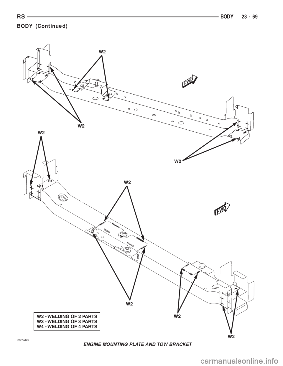
ENGINE MOUNTING PLATE AND TOW BRACKET
RSBODY23-69
BODY (Continued)
Page 3570 of 4284
COWL GRILLE
REMOVAL
(1) Remove wiper arms. (Refer to 8 - ELECTRI-
CAL/WIPERS/WASHERS/WIPER ARMS -
REMOVAL)
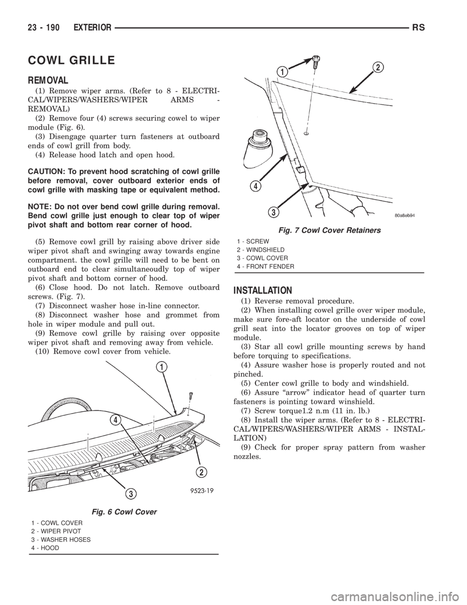
(2) Remove four (4) screws securing cowel to wiper
module (Fig. 6).
(3) Disengage quarter turn fasteners at outboard
ends of cowl grill from body.
(4) Release hood latch and open hood.
CAUTION: To prevent hood scratching of cowl grille
before removal, cover outboard exterior ends of
cowl grille with masking tape or equivalent method.
NOTE: Do not over bend cowl grille during removal.
Bend cowl grille just enough to clear top of wiper
pivot shaft and bottom rear corner of hood.
(5) Remove cowl grill by raising above driver side
wiper pivot shaft and swinging away towards engine
compartment. the cowl grille will need to be bent on
outboard end to clear simultaneoudly top of wiper
pivot shaft and bottom corner of hood.
(6) Close hood. Do not latch. Remove outboard
screws. (Fig. 7).
(7) Disconnect washer hose in-line connector.
(8) Disconnect washer hose and grommet from
hole in wiper module and pull out.
(9) Remove cowl grille by raising over opposite
wiper pivot shaft and removing away from vehicle.
(10) Remove cowl cover from vehicle.
INSTALLATION
(1) Reverse removal procedure.
(2) When installing cowel grille over wiper module,
make sure fore-aft locator on the underside of cowl
grill seat into the locator grooves on top of wiper
module.
(3) Star all cowl grille mounting screws by hand
before torquing to specifications.
(4) Assure washer hose is properly routed and not
pinched.
(5) Center cowl grille to body and windshield.
(6) Assure ªarrowº indicator head of quarter turn
fasteners is pointing toward winshield.
(7) Screw torque1.2 n.m (11 in. lb.)
(8) Install the wiper arms. (Refer to 8 - ELECTRI-
CAL/WIPERS/WASHERS/WIPER ARMS - INSTAL-
LATION)
(9) Check for proper spray pattern from washer
nozzles.
Fig. 6 Cowl Cover
1 - COWL COVER
2 - WIPER PIVOT
3 - WASHER HOSES
4 - HOOD
Fig. 7 Cowl Cover Retainers
1 - SCREW
2 - WINDSHIELD
3 - COWL COVER
4 - FRONT FENDER
23 - 190 EXTERIORRS
Page 3571 of 4284
EXTERIOR NAME PLATES -
TAPE ATTACHED
REMOVAL
(1) Mark reference points before removing.
(2) Using a heat gun gently apply heat in a circu-
lar motion to loosen the adhesive bond.
(3) Using a nonmetallic prying device, such as a
plastic or wood trim stick gently pry up at corners
and remove.
(4) Clean off all traces of adhesive or double sided
tape from the panel with a general purpose adhesive
remover.
INSTALLATION
(1) Clean panel surface with isopropy alcohol.
(2) Align badgeing to reference points.
(3) Install and press securely to full adhesive con-
tact
(4) Clean away any reference points.
EXTERIOR NAME PLATES -
ADHESIVE ATTACHED
REMOVAL
(1) Mark reference points before removing.
(2) Using a heat gun gently apply heat in a circu-
lar motion to loosen the adhesive bond.
(3) With your fingernail lift up and peel away
badgeing/tape from panel, using a heat gun as you
go.
(4) Clean off all traces of adhesive from the pan-
el(s) with a general purpose adhesive remover.
INSTALLATION
(1) Clean panel surface with isopropy alcohol.
(2) Remove paper carrier and align badgeing/tape
to reference points or adjacent panel.
(3) Install and press securely, using a plastic
spreader to eliminate all air bubbles.
(4) Remove top protective carrier.
(5) Clean away any reference points.
FRONT FENDER
REMOVAL
(1) Remove headlamp housing. (Refer to 8 - ELEC-
TRICAL/LAMPS/LIGHTING - EXTERIOR/HEAD-
LAMP UNIT - REMOVAL)
(2) Remove mud guard.
(3) Remove inner splash shield.
(4) Remove fender to fascia nuts.(5) Remove outboard cowl grille/fender bracket
screw.
(6) Remove fender bolt to lower rocker panel.
(7) Remove fender bolt to lower cowl.
(8) Pull fascia away from fender.
(9) Remove bolts attaching fender to upper rail.
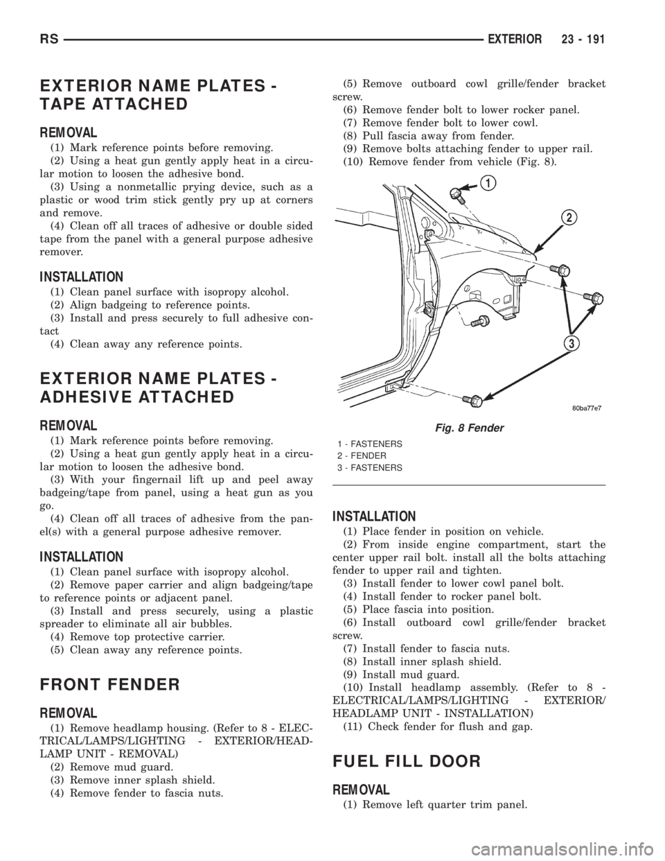
(10) Remove fender from vehicle (Fig. 8).
INSTALLATION
(1) Place fender in position on vehicle.
(2) From inside engine compartment, start the
center upper rail bolt. install all the bolts attaching
fender to upper rail and tighten.
(3) Install fender to lower cowl panel bolt.
(4) Install fender to rocker panel bolt.
(5) Place fascia into position.
(6) Install outboard cowl grille/fender bracket
screw.
(7) Install fender to fascia nuts.
(8) Install inner splash shield.
(9) Install mud guard.
(10) Install headlamp assembly. (Refer to 8 -
ELECTRICAL/LAMPS/LIGHTING - EXTERIOR/
HEADLAMP UNIT - INSTALLATION)
(11) Check fender for flush and gap.
FUEL FILL DOOR
REMOVAL
(1) Remove left quarter trim panel.
Fig. 8 Fender
1 - FASTENERS
2 - FENDER
3 - FASTENERS
RSEXTERIOR23 - 191
Page 3574 of 4284
(5) Install fuel filler housing to outer quarter
panel.
(6) Verify that all clips on fuel filler housing are
fully engaged to outer quarter panel.
(7) Engage fuel filler lockout link into clip on fuel
fill blocker latch arm.
(8) Install water shield patch covering access hole
in C-pillar.
(9) Install left quarter trim panel.
GRILLE OPENING
REINFORCEMENT
REMOVAL
(1) Release hood latch and open hood.
(2) Remove bolts attaching hood latch to cross-
member and position latch out of the way.
(3) Remove radiator sight shield.
(4) Remove engine air inlet resonator.
(5) Remove hood cable.
(6) Remove hood prop rod.
(7) Remove screw attaching coolant recovery bottle
to crossmember.
(8) Remove bolts attaching radiator isolators to
crossmember.
(9) Remove bolts attaching ends of crossmember to
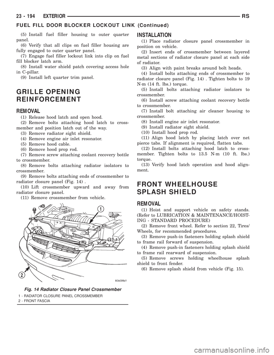
radiator closure panel (Fig. 14) .
(10) Lift crossmember upward and away from
radiator closure panel.
(11) Remove crossmember from vehicle.
INSTALLATION
(1) Place radiator closure panel crossmember in
position on vehicle.
(2) Insert ends of crossmember between layered
metal sections of radiator closure panel at each side
of radiator.
(3) Align with paint breaks around bolt heads.
(4) Install bolts attaching ends of crossmember to
radiator closure panel (Fig. 14) . Tighten bolts to 19
N´m (14 ft. lbs.) torque.
(5) Install bolts attaching radiator isolators to
crossmember.
(6) Install screw attaching coolant recovery bottle
to crossmember.
(7) Install bolt attaching air cleaner housing to
crossmember.
(8) Install engine air inlet resonator.
(9) Install radiator sight shield.
(10) Install hood prop rod.
(11) Align hood latch by placing latch over net
pierce tabs. If alignment is required, flatten tabs.
(12) Install bolts attaching hood latch to cross-
member. Tighten bolts to 13.5 N´m (10 ft. lbs.)
torque.
(13) Verify hood latch operation and hood align-
ment.
FRONT WHEELHOUSE
SPLASH SHIELD
REMOVAL
(1) Hoist and support vehicle on safety stands.
(Refer to LUBRICATION & MAINTENANCE/HOIST-
ING - STANDARD PROCEDURE)
(2) Remove front wheel. Refer to section 22, Tires/
Wheels, for recommended procedures.
(3) Remove push-in fasteners holding splash shield
to frame rail forward of suspension.
(4) Remove push-in fasteners holding splash shield
to frame rail rearward of suspension.
(5) Remove screws holding wheelhouse splash
shield to front fender.
(6) Remove splash shield from vehicle (Fig. 15).
Fig. 14 Radiator Closure Panel Crossmember
1 - RADIATOR CLOSURE PANEL CROSSMEMBER
2 - FRONT FASCIA
23 - 194 EXTERIORRS
FUEL FILL DOOR BLOCKER LOCKOUT LINK (Continued)
Page 3581 of 4284
(4) Align hood latch by placing latch over net
pierced tabs. If alignment is required, flatten or
grind tabs.
(5) Verify hood operation and alignment. Adjust as
necessary.
(6) Tighten attaching bolts to 13.5 N´m (10 ft. lbs.)
torque.
LATCH RELEASE CABLE
REMOVAL
(1) Remove hood latch.
(2) Disengage cable end from hood latch locking
mechanism.
(3) Slide cable case end sideways in keyhole slot of
hood latch while pinching barb on cable case closed.
(4) Remove cable from latch (Fig. 4).
(5) Remove hood release handle from instrument
panel.
(6) Disengage rubber grommet cable insulator
from hole in dash panel.
(7) Attach a suitable length of mechanic's wire to
latch end of cable to assist cable installation.
(8) Route cable back from latch through engine
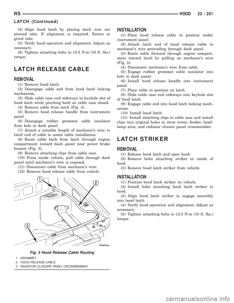
compartment toward dash panel near power brake
booster (Fig. 5).
(9) Remove attaching clips from cable case.
(10) From inside vehicle, pull cable through dash
panel until mechanic's wire is exposed.
(11) Disconnect cable from mechanic's wire.
(12) Remove hood release cable from vehicle.
INSTALLATION
(1) Place hood release cable in position under
instrument panel.
(2) Attach latch end of hood release cable to
mechanic's wire protruding through dash panel.
(3) Route cable forward through engine compart-
ment toward latch by pulling on mechanic's wire
(Fig. 5).
(4) Disconnect mechanic's wire from cable.
(5) Engage rubber grommet cable insulator into
hole in dash panel.
(6) Install hood release handle into instrument
panel.
(7) Place cable in position on latch.
(8) Slide cable case end sideways into keyhole slot
of hood latch.
(9) Engage cable end into hood latch locking mech-
anism.
(10) Install hood latch.
(11) Install attaching clips to cable case and install
clips into original holes in strut tower, fender, head-
lamp area, and radiator closure panel crossmember.
LATCH STRIKER
REMOVAL
(1) Release hood latch and open hood.
(2) Remove bolts attaching striker to inside of
hood.
(3) Remove hood latch striker from vehicle.
INSTALLATION
(1) Position hood latch striker on vehicle.
(2) Install bolts attaching hood latch striker to
hood.
(3) Align hood latch striker to engage smoothly
into hood latch.
(4) Verify hood operation and alignment. Adjust as
necessary.
(5) Tighten attaching bolts to 13.5 N´m (10 ft. lbs.)
torque.
Fig. 5 Hood Release Cable Routing
1 - GROMMET
2 - HOOD RELEASE CABLE
3 - RADIATOR CLOSURE PANEL CROSSMEMBER
RSHOOD23 - 201
LATCH (Continued)
Page 3601 of 4284
PAINT CODE
DESCRIPTION
Exterior vehicle body colors are identified on the
Body Code plate. The plate is located in the engine
compartment on the radiator closure panel cross-
member. Refer to the Introduction section at the
front of this manual for body code plate description.
The paint code is also identified on the Vehicle Safety
Certification Label which is located on the drivers
door shut face. The first digit of the paint code listed
on the vehicle indicates the sequence of application,
ie: P= primary coat, Q= secondary coat. The codes
listed in the color code charts are used for manufac-
turing purposes. The first digit may vary from the
Body Code Plate.
BASE COAT/CLEAR COAT
FINISH
DESCRIPTION
On most vehicles a two-part paint application (base
coat/clear coat) is used. Color paint that is applied to
primer is called base coat. The clear coat protects the
base coat from ultraviolet light and provides a dura-
ble high-gloss finish.
CAUTION:
Do not use abrasive chemicals or compounds on
painted surfaces. Damage to finish can result.
Do not use harsh alkaline based cleaning solvents
on painted surfaces. Damage to finish or color can
result.
PAINT TOUCH-UP
DESCRIPTION
When a painted metal surface has been scratched
or chipped, it should be touched-up as soon as possi-
ble to avoid corrosion. For best results, use Moparž
Scratch Filler/Primer, Touch-Up Paints and Clear Top
Coat. Refer to Introduction group of this manual for
Body Code Plate information.
WARNING:
USE A OSHA APPROVED BREATHING FILTER
WHEN SPRAYING PAINT OR SOLVENTS IN A CON-
FINED AREA. PERSONAL INJURY CAN RESULT.
OPERATION
(1) Scrape loose paint and corrosion from inside
scratch or chip.(2) Clean affected area with Moparž Tar/Road Oil
Remover, and allow to dry.
(3) Fill the inside of the scratch or chip with a coat
of filler/primer. Do not overlap primer onto good sur-
face finish. The applicator brush should be wet
enough to puddle-fill the defect without running. Do
not stroke brush applicator on body surface. Allow
the filler/primer to dry hard.
(4) Cover the filler/primer with color touch-up
paint. Do not overlap touch-up color onto the original
color coat around the scratch or chip. Butt the new
color to the original color, if possible. Do not stroke
applicator brush on body surface. Allow touch-up
paint to dry hard.
(5) On vehicles without clear coat, the touch-up
color can be lightly finesse sanded (1500 grit) and
polished with rubbing compound.
(6) On vehicles with clear coat, apply clear top coat
to touch-up paint with the same technique as
described in Step 4. Allow clear top coat to dry hard.
If desired, Step 5 can be performed on clear top coat.
WARNING:
AVOID PROLONGED SKIN CONTACT WITH PETRO-
LEUM OR ALCOHOL ± BASED CLEANING SOL-
VENTS. PERSONAL INJURY CAN RESULT.
AVOID PROLONGED SKIN CONTACT WITH PETRO-
LEUM OR ALCOHOL ± BASED CLEANING SOL-
VENTS. PERSONAL INJURY CAN RESULT.
WET SANDING/BUFFING &
POLISHING
DESCRIPTION
Minor acid etching, orange peel, or smudging in
clear coat or single-stage finishes can be reduced
with light finesse sanding, hand buffing, and polish-
ing.If the finish has been finesse sanded in the
past, it cannot be repeated. Finesse sanding
operation should be performed by a trained
automotive paint technician.
CAUTION: Do not remove clear coat finish, if
equipped. Base coat paint must retain clear coat for
durability.
RSPAINT23 - 221