2001 CHRYSLER VOYAGER seat adjustment
[x] Cancel search: seat adjustmentPage 45 of 4284
the CPA is not properly engaged, a voltage on pin 38
will be interpreted as an unseated connector and a
fault will set.
Flash programming voltage Ð20 volt input on
pin 42. When a DRBIIItis connected and the
proper flash reprogramming sequence is selected,
the 20 volt signal will be applied through pin 42.
3.9 HEATING & A/C
3.9.1 AUTOMATIC TEMPERATURE
CONTROL (ATC)
3.9.1.1 CABIN HEATER
For vehicles equipped with a diesel engine, a
Cabin Heater is used in conjunction with the HVAC
system. The Cabin Heater is designed to supply the
vehicle's occupants with heat prior to the engine
reaching operating temperature. For additional in-
formation on this system, refer to Cabin Heater
under General Information and Diagnostic Proce-
dures in this manual.
3.9.1.2 SYSTEM OPERATION
The Automatic Temperature Control (ATC) sys-
tem provides fully adjustable three zone climate
control; Driver front zone, Passenger Front zone
and Rear zone. The following is a list of ATC
controls and features:
± a POWER button which allows the operator to
turn the system completely off.
± AUTO HIGH/LOW switch allows the operator
to select what rate (fan speed) the system will
provide the selected comfort level.
± DRIVER, REAR and PASSENGER rocker
switches to select desired temperature for each
zone.
± Recirculation button allows cooling air to be
recirculated which maximizes cooling ability.
± A/C select button allows the operator to turn
the A/C compressor off.
± Defroster button allows the operator to turn on
the defroster independently during automatic
control.
± Fan control rotary switch for selecting fan
speed.
± Mode rotary switch for selecting heating/
cooling direction.
± REAR SYSTEM rotary switch for activating
the Rear ATC Switch allowing intermediate
passenger control over rear climate control.
3.9.1.3 BLOWER MOTOR OPERATION
The Automatic Temperature Control (ATC) front
and rear blower control provides continuously vari-
able control of air flow rate to meet occupant
comfort requirements. Pulse width modulation of
the blower motor power allows the front and rear
blower to operate at any speed from off to full speed.
When front or rear blower operation is required, the
ATC sends a PCI Bus message to the Front Control
Module (FCM) requesting blower relay ON. The
FCM provides a ground for the front and rear
blower motor relay coils, activating both relays. The
front and rear blower relays provide 12 volts to
their respective blower motor power modules. Each
module provides a 12 volt blower motor control
signal to the ATC. The ATC provides a pulse width
modulated (duty-cycle) ground signal to this circuit
based on climate requirements. The higher voltage
on the signal circuit (less duty-cycle ground) the
lower the blower speed request. The lower voltage
on the signal circuit (more duty-cycle ground) the
higher the blower speed request.
3.9.1.4 INFRARED SENSORS
The ATC system uses infrared (I/R) sensors to
monitor and control oocupant comfort levels. This
sensing system replaces interior air temperature
and solar sensors which required complex control
programs to maintain occupant comfort levels. The
front I/R sensor is located in the instrument panel
center bezel outlet. The rear I/R sensor is located in
the rear overhead mounted ATC switch.
3.9.1.5 REAR ATC SWITCH
The rear ATC switch is mounted in the headliner.
The switch contains a rotary adjustment for fan
speed, a rotary adjustment for mode selection, a
push button switch for temperature selection and a
digital display of the selected temperature.
3.9.1.6 COOLDOWN TESTING
The ATC provides a feature referred to as a
Cooldown Test. This test is initiated using the
DRBIIItand is designed to check the performance
of the air conditioning system. The ATC will not
perform this test if the ambient air temperature is
below 12ÉC (53ÉF). During the test, the ATC com-
pares the ambient air temperature to the evapora-
tor temperature sensor. To pass the cooldown test,
the evap temperature sensor must drop -6ÉC (20ÉF)
below ambient temperature within 2 minutes of
start of test. At the completion of the cooldown test
the DRBIIItwill display one of the following mes-
sages indicating test outcome:
± Cooldown Test Passed
± Cooldown Test Failed
16
GENERAL INFORMATION
Page 52 of 4284
contains a potentiometer to monitor the seat posi-
tion. To monitor the position of the motor, the
MSMM sends out a 5-volt reference on the sensor
supply circuit. The sensor is grounded back to the
module on a common ground circuit. Based on the
position of the sensor, the MSMM monitors the
voltage change through the sensor on a separate
signal circuit.
The MSMM stores the input value of each of the
four seat potentiometers in memory when the sys-
tem requests a set. The driver can initiate a mem-
ory recall, using either the door mounted memory
switch or the RKE transmitter (if the remote linked
to memory feature is enabled via the EVIC). When
initiated, the MSMM adjusts the four seat sensors
(by using the motors) to match the memorized seat
position data.
For safety, the memory seat recall is disabled by
the MSMM when the vehicle is out of park position
or if the speed is not zero. Any obstruction to seat
movement over a 2-second delay will cause the seat
to stop moving in which case a stalled motor would
be detected by the MSMM and the corresponding
seat output would be deactivated. However, if the
object obstructing the seat is removed, the seat will
function normally again.
3.13.2 MEMORY MIRRORS
Each outside mirror contains vertical and hori-
zontal bi-directional drive positioning motors and
position sensors. The MSMM provides a 5-volt
reference on the signal circuit to each position
sensor. The sensors share a common ground circuit.
The MSMM monitors the position of the mirror
motors by measuring the voltage on each signal
circuit. When a memory position is set, the MSMM
monitors and stores the position of the outside
mirrors. The MSMM adjusts the mirrors to the
appropriate positions when a memory recall mes-
sage is received from the RKE or is requested from
the memory set switch.
The power mirror switch during non-memory
operation operates both mirrors independently of
the MSMM.
3.14 OVERHEAD CONSOLE
3.14.1 COMPASS/MINI-TRIP COMPUTER
(CMTC)
The compass/mini-trip computer is located in the
overhead console. It displays to the driver the
direction the vehicle is traveling and the current
outside temperature, as well as the following trav-
eler navigational information: average fuel econ-
omy (AVG ECO), distance to empty (DTE), instan-
taneous fuel economy (ECO), elapsed time (ET),and trip odometer (ODO). The information needed
for the CMTC functions is received over the PCI bus
from other modules.
3.14.2 ELECTRONIC VEHICLE
INFORMATION CENTER (EVIC)
The Electronic Vehicle Information Center
(EVIC) includes all the same functions and is lo-
cated in the same area as the Compass/Mini-Trip
Computer, but it adds a number of warning mes-
sages. Also, the EVIC messages are spelled out on
the screen, for example, DISTANCE TO EMPTY,
where the Mini-Trip Computer displays only shows
DTE.
If the compass/mini-trip computer or EVIC has
been replaced, it may be necessary to reset the
calibration.
3.14.3 SETTING THE COMPASS
The compass/mini-trip computer and EVIC are
self-calibrated and requires no adjustment. The
word CAL will be displayed to indicate that the
compass is in the fast calibrating mode. CAL will
turn off after the vehicle has gone in three complete
circles without stopping, in an area free of magnetic
disturbance.
If the module displays the temperature while the
compass is blank or shows a false reading, the
vehicle must be demagnetized. See the service man-
ual for the proper procedure.
If the compass still goes blank after the vehicle is
demagnetized, the compass/mini-trip/EVIC module
must be replaced.
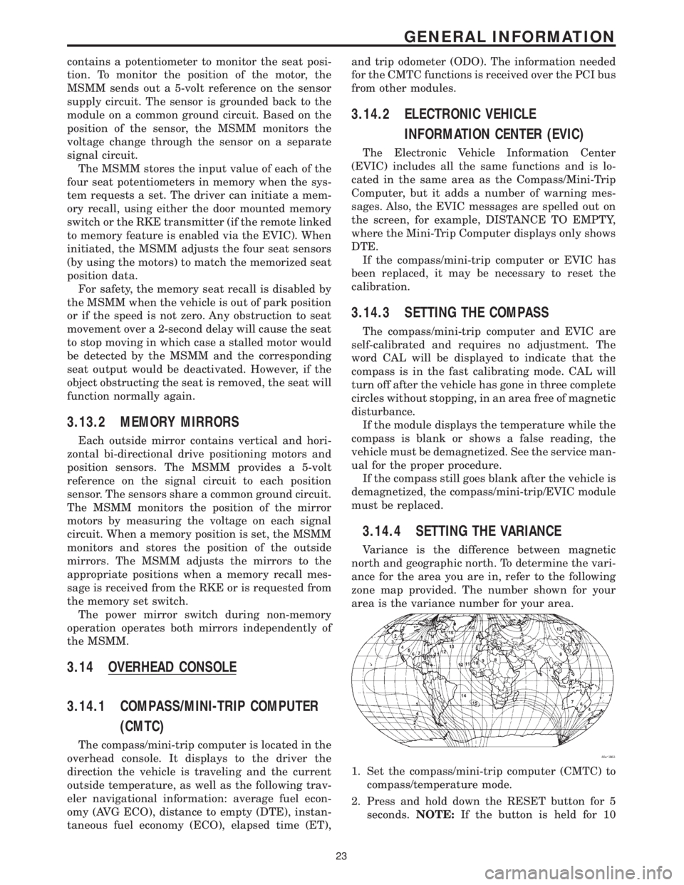
3.14.4 SETTING THE VARIANCE
Variance is the difference between magnetic
north and geographic north. To determine the vari-
ance for the area you are in, refer to the following
zone map provided. The number shown for your
area is the variance number for your area.
1. Set the compass/mini-trip computer (CMTC) to
compass/temperature mode.
2. Press and hold down the RESET button for 5
seconds.NOTE:If the button is held for 10
23
GENERAL INFORMATION
Page 1638 of 4284
The outboard rear disc brake shoes (pads) are side-
oriented. The shoes are marked indicating which side
they belong on.
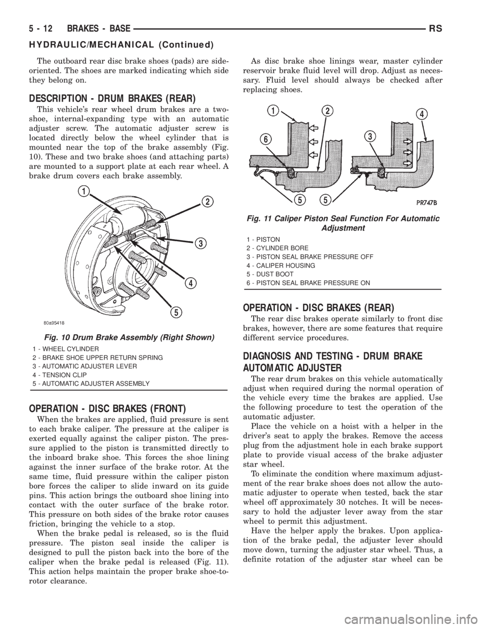
DESCRIPTION - DRUM BRAKES (REAR)
This vehicle's rear wheel drum brakes are a two-
shoe, internal-expanding type with an automatic
adjuster screw. The automatic adjuster screw is
located directly below the wheel cylinder that is
mounted near the top of the brake assembly (Fig.
10). These and two brake shoes (and attaching parts)
are mounted to a support plate at each rear wheel. A
brake drum covers each brake assembly.
OPERATION - DISC BRAKES (FRONT)
When the brakes are applied, fluid pressure is sent
to each brake caliper. The pressure at the caliper is
exerted equally against the caliper piston. The pres-
sure applied to the piston is transmitted directly to
the inboard brake shoe. This forces the shoe lining
against the inner surface of the brake rotor. At the
same time, fluid pressure within the caliper piston
bore forces the caliper to slide inward on its guide
pins. This action brings the outboard shoe lining into
contact with the outer surface of the brake rotor.
This pressure on both sides of the brake rotor causes
friction, bringing the vehicle to a stop.
When the brake pedal is released, so is the fluid
pressure. The piston seal inside the caliper is
designed to pull the piston back into the bore of the
caliper when the brake pedal is released (Fig. 11).
This action helps maintain the proper brake shoe-to-
rotor clearance.As disc brake shoe linings wear, master cylinder
reservoir brake fluid level will drop. Adjust as neces-
sary. Fluid level should always be checked after
replacing shoes.
OPERATION - DISC BRAKES (REAR)
The rear disc brakes operate similarly to front disc
brakes, however, there are some features that require
different service procedures.
DIAGNOSIS AND TESTING - DRUM BRAKE
AUTOMATIC ADJUSTER
The rear drum brakes on this vehicle automatically
adjust when required during the normal operation of
the vehicle every time the brakes are applied. Use
the following procedure to test the operation of the
automatic adjuster.
Place the vehicle on a hoist with a helper in the
driver's seat to apply the brakes. Remove the access
plug from the adjustment hole in each brake support
plate to provide visual access of the brake adjuster
star wheel.
To eliminate the condition where maximum adjust-
ment of the rear brake shoes does not allow the auto-
matic adjuster to operate when tested, back the star
wheel off approximately 30 notches. It will be neces-
sary to hold the adjuster lever away from the star
wheel to permit this adjustment.
Have the helper apply the brakes. Upon applica-
tion of the brake pedal, the adjuster lever should
move down, turning the adjuster star wheel. Thus, a
definite rotation of the adjuster star wheel can be
Fig. 10 Drum Brake Assembly (Right Shown)
1 - WHEEL CYLINDER
2 - BRAKE SHOE UPPER RETURN SPRING
3 - AUTOMATIC ADJUSTER LEVER
4 - TENSION CLIP
5 - AUTOMATIC ADJUSTER ASSEMBLY
Fig. 11 Caliper Piston Seal Function For Automatic
Adjustment
1 - PISTON
2 - CYLINDER BORE
3 - PISTON SEAL BRAKE PRESSURE OFF
4 - CALIPER HOUSING
5 - DUST BOOT
6 - PISTON SEAL BRAKE PRESSURE ON
5 - 12 BRAKES - BASERS
HYDRAULIC/MECHANICAL (Continued)
Page 1685 of 4284
(12) Install the wheel speed sensor on the hub/
bearing and adapter. Install the wheel speed sensor
attaching bolt (Fig. 89). Tighten the wheel speed sen-
sor attaching bolt to a torque of 12 N´m (105 in. lbs).
(13) Install the park brake cable into its mounting
hole in the adapter.Be sure all the locking tabs
on the park brake cable retainer are expanded
out to ensure the cable will not pull out of the
adapter.
(14) Install the end of the park brake cable on the
park brake actuator lever (Fig. 87).
NOTE: The horseshoe clip must be installed and
installed properly when the park brake cable is
installed in the adapter. The purpose of the horse-
shoe clip is to prevent park brake cable retainer
from moving in the adapter. If horseshoe clip is not
installed the park brake cable retainer will rattle in
the adapter.
(15) Install aNEWhorseshoe clip on the park
brake cable retainer (Fig. 87). The horseshoe clip is
installed between the retainer for the park brake
cable and the adapter. Horseshoe clip must be
installed with the curved end of the clip pointing
straight up and the edge of the curved end facing
toward the rear of the vehicle (Fig. 87).
(16) Remove the locking pliers (Fig. 83) from the
front park brake cable.
(17) Adjust the park brake drum-in-hat brake
shoes. (Refer to 5 - BRAKES/PARKING BRAKE/
SHOES - ADJUSTMENTS).
(18) Install the rotor on the hub/bearing.
(19) Carefully lower caliper and brake shoes over
rotor and onto the adapter using the reverse proce-
dure for removal (Fig. 85).
CAUTION: When installing guide pin bolts extreme
caution should be taken not to crossthread the cal-
iper guide pin bolts.
(20) Install the caliper guide pin bolts (Fig. 84).
Tighten the guide pin bolts to a torque of 22 N´m
(192 in. lbs.).
(21) Clean all foreign material off the threads of
the outer C/V joint stub shaft. Install the washer and
hub nut (Fig. 82) on the stub shaft of the outer C/V
joint.
(22) Set the parking brake.
(23) Tighten the hub nut to a torque of 244 N´m
(180 ft. lbs.).
(24) Install the spring washer (Fig. 81) on the stub
shaft of the outer C/V joint.
(25) Install the nut retainer and cotter pin (Fig.
80) on the stub shaft of the outer C/V joint.
(26) Install the wheel and tire assembly. Tighten
the wheel mounting stud nuts in proper sequenceuntil all nuts are torqued to half specification. Then
repeat the tightening sequence to the full specified
torque of 135 N´m (100 ft. lbs.).
(27) Lower vehicle.
(28) Fully apply and release the park brake pedal
one time. This will seat and correctly adjust the park
brake cables.
CAUTION: Before moving vehicle, pump the brake
pedal several times to insure the vehicle has a firm
brake pedal to adequately stop vehicle.
(29) Road test the vehicle and make several stops
to wear off any foreign material on the brakes and to
seat the brake shoe linings.
ADJUSTMENT - PARKING BRAKE SHOES
CAUTION: Before adjusting the park brake shoes be
sure that the park brake pedal is in the fully
released position. If park brake pedal is not in the
fully released position, the park brake shoes can
not be accurately adjusted.
(1) Raise vehicle.
(2) Remove tire and wheel.
(3) Remove disc brake caliper from caliper adapter
(Fig. 100). (Refer to 5 - BRAKES/HYDRAULIC/ME-
CHANICAL/DISC BRAKE CALIPERS - REMOVAL).
(4) Remove rotor from hub/bearing.
Fig. 100 Disc Brake Caliper
1 - DISC BRAKE CALIPER
2 - ADAPTER
3 - AXLE
4 - GUIDE PIN BOLTS
5 - DRIVESHAFT (AWD MODELS ONLY)
RSBRAKES - BASE5-59
SHOES (Continued)
Page 1692 of 4284
INSTALLATION - PARKING BRAKE CABLE
(LEFT REAR)
(1) Install the rear parking brake cable in the
brake support plate. Insert cable housing retainer
into brake support plate making certain that cable
housing retainer fingers lock the housing and
retainer firmly into place.
(2) Attach the parking brake cable onto the park
brake actuator lever.
(3) Install the brake shoes on the rear brake sup-
port plate. (Refer to 5 - BRAKES/HYDRAULIC/ME-
CHANICAL/BRAKE PADS/SHOES -
INSTALLATION).
(4) Insert cable housing retainer into body outrig-
ger bracket making certain that cable housing
retainer fingers lock the housing firmly into place.
(5) Connect rear parking brake cable to the equal-
izer bracket (Fig. 114).
(6) Install brake drum, and wheel and tire assem-
bly.
(7) Remove the locking pliers from the front park
brake cable. This will automatically adjust the park
brake cables.
(8) Apply and release park brake pedal 1 time.
This will seat the park brake cables.
ADJUSTMENT - CABLES
The park brake cables on this vehicle have an
automatic self adjuster built into the park brake
pedal mechanism. When the foot operated park brake
pedal is in its released (upward most) position, a
clock spring automatically adjusts the park brake
cables. The park brake cables are adjusted (ten-
sioned) just enough to remove all the slack from the
cables. The automatic adjuster system will not over
adjust the cables causing rear brake drag.
Due to the automatic adjust feature of the park
brake pedal, adjustment of the parking brake cables
on these vehicles relies on proper drum brake and
park brake shoe adjustment. (Refer to 5 - BRAKES/
HYDRAULIC/MECHANICAL/DRUM - ADJUST-
MENTS) and (Refer to 5 - BRAKES/PARKING
BRAKE/SHOES - ADJUSTMENTS).
When the park brake pedal is applied the self
adjuster is by-passed and the pedal operates nor-
mally to engage the park brakes.
When a service procedure needs to be performed on
the park brake pedal or the park brake cables, the
automatic self adjuster can be manually locked out
by the service technician.
5 - 66 BRAKES - BASERS
CABLES (Continued)
Page 1807 of 4284
CONDITION POSSIBLE CAUSE CORRECTION
4. POOR ANTENNA
CONNECTION AT
RADIO OR IN LINE.4. SEAT CONNECTOR.
NO/POOR TAPE
OPERATION.1. FAULTY TAPE. 1. INSERT KNOWN GOOD TAPE AND TEST OPERATION.
2. FOREIGN OBJECTS
BEHIND TAPE DOOR.2. REMOVE FOREIGN OBJECTS AND TEST OPERATION.
3. DIRTY CASSETTE
TAPE HEAD.3. CLEAN HEAD WITH MOPAR CASSETTE HEAD CLEANER.
4. FAULTY TAPE DECK. 4. EXCHANGE OR REPLACE RADIO, IF REQUIRED.
NO COMPACT
DISC
OPERATION1. FAULTY CD. 1. INSERT KNOWN GOOD CD AND TEST OPERATION.
2. FOREIGN MATERIAL
ON CD.2. CLEAN CD AND TEST OPERATION.
3. CONDENSATION ON
CD OR OPTICS.3. ALLOW TEMPERATURE OF VEHICLE INTERIOR TO
STABILIZE AND TEST OPERATION.
4. FAULTY CD PLAYER. 4. EXCHANGE OR REPLACE RADIO, IF REQUIRED.
ANTENNA BODY & CABLE
DESCRIPTION
All models use a fixed-length stainless steel rod-
type antenna mast, installed at the right front fender
of the vehicle. The antenna mast is connected to the
center wire of the coaxial antenna cable, and is not
grounded to any part of the vehicle.
OPERATION
To minimize static, the antenna base must have a
good ground. The coaxial antenna cable shield (the
outer wire mesh of the cable) is grounded to the
antenna base and the radio chassis.
The antenna coaxial cable has an additional dis-
connect, located near the right end of the instrument
panel. This additional disconnect allows the instru-
ment panel assembly to be removed and installed
without removing the radio.
The factory-installed Electronically Tuned Radios
(ETRs) automatically compensate for radio antenna
trim. Therefore, no antenna trimmer adjustment is
required or possible when replacing the receiver or
the antenna.
DIAGNOSIS AND TESTING
WARNING:
ON VEHICLES EQUIPPED WITH AIRBAGS, REFER
TO ELECTRICAL, RESTRAINTS BEFORE ATTEMPT-ING ANY STEERING WHEEL, STEERING COLUMN,
OR INSTRUMENT PANEL COMPONENT DIAGNOSIS
OR SERVICE. FAILURE TO TAKE THE PROPER
PRECAUTIONS COULD RESULT IN ACCIDENTAL
AIRBAG DEPLOYMENT AND POSSIBLE PERSONAL
INJURY.
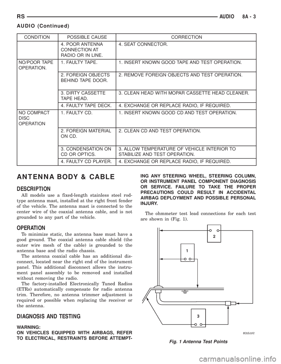
The ohmmeter test lead connections for each test
are shown in (Fig. 1).
Fig. 1 Antenna Test Points
RSAUDIO8A-3
AUDIO (Continued)
Page 1948 of 4284
CAUTION: The switch can only be adjusted once.
That is during initial installation of the switch. If the
switch is not adjusted properly or has been
removed for some service, a new switch must be
installed and adjusted.
REMOVAL - BRAKE LAMP SWITCH
(1) Disconnect and isolate the battery negative
cable from its post on the battery.
(2) Remove silencer panel below steering column
and knee blocker.
(3) Remove the brake lamp switch by rotating the
switch in a counterclockwise direction approximately
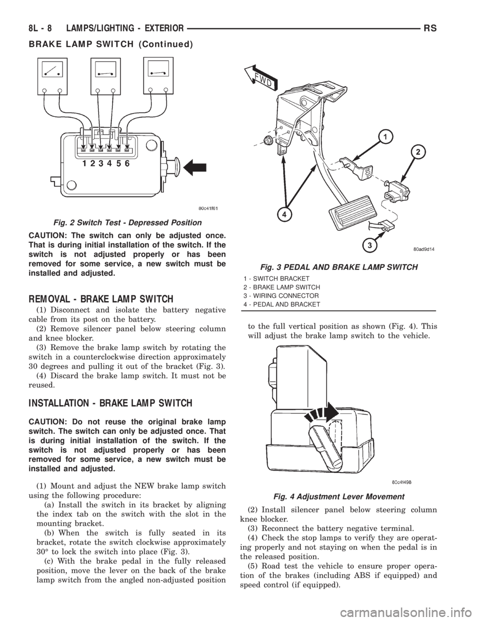
30 degrees and pulling it out of the bracket (Fig. 3).
(4) Discard the brake lamp switch. It must not be
reused.
INSTALLATION - BRAKE LAMP SWITCH
CAUTION: Do not reuse the original brake lamp
switch. The switch can only be adjusted once. That
is during initial installation of the switch. If the
switch is not adjusted properly or has been
removed for some service, a new switch must be
installed and adjusted.
(1) Mount and adjust the NEW brake lamp switch
using the following procedure:
(a) Install the switch in its bracket by aligning
the index tab on the switch with the slot in the
mounting bracket.
(b) When the switch is fully seated in its
bracket, rotate the switch clockwise approximately
30É to lock the switch into place (Fig. 3).
(c) With the brake pedal in the fully released
position, move the lever on the back of the brake
lamp switch from the angled non-adjusted positionto the full vertical position as shown (Fig. 4). This
will adjust the brake lamp switch to the vehicle.
(2) Install silencer panel below steering column
knee blocker.
(3) Reconnect the battery negative terminal.
(4) Check the stop lamps to verify they are operat-
ing properly and not staying on when the pedal is in
the released position.
(5) Road test the vehicle to ensure proper opera-
tion of the brakes (including ABS if equipped) and
speed control (if equipped).
Fig. 2 Switch Test - Depressed Position
Fig. 3 PEDAL AND BRAKE LAMP SWITCH
1 - SWITCH BRACKET
2 - BRAKE LAMP SWITCH
3 - WIRING CONNECTOR
4 - PEDAL AND BRACKET
Fig. 4 Adjustment Lever Movement
8L - 8 LAMPS/LIGHTING - EXTERIORRS
BRAKE LAMP SWITCH (Continued)
Page 1967 of 4284
PARK/TURN SIGNAL LAMP
REMOVAL
(1) Disconnect and isolate the battery negative
cable.
(2) Remove the headlamp unit.
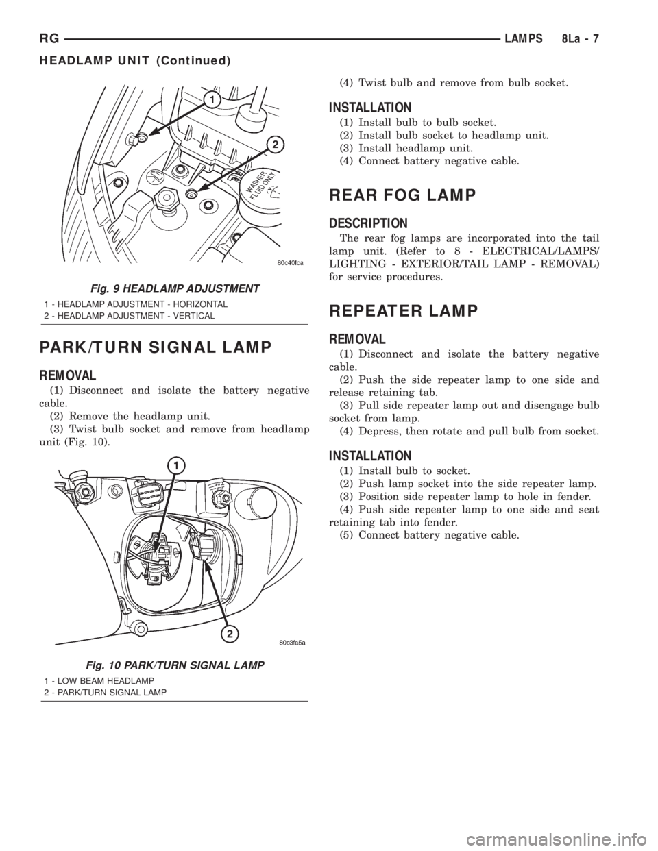
(3) Twist bulb socket and remove from headlamp
unit (Fig. 10).(4) Twist bulb and remove from bulb socket.
INSTALLATION
(1) Install bulb to bulb socket.
(2) Install bulb socket to headlamp unit.
(3) Install headlamp unit.
(4) Connect battery negative cable.
REAR FOG LAMP
DESCRIPTION
The rear fog lamps are incorporated into the tail
lamp unit. (Refer to 8 - ELECTRICAL/LAMPS/
LIGHTING - EXTERIOR/TAIL LAMP - REMOVAL)
for service procedures.
REPEATER LAMP
REMOVAL
(1) Disconnect and isolate the battery negative
cable.
(2) Push the side repeater lamp to one side and
release retaining tab.
(3) Pull side repeater lamp out and disengage bulb
socket from lamp.
(4) Depress, then rotate and pull bulb from socket.
INSTALLATION
(1) Install bulb to socket.
(2) Push lamp socket into the side repeater lamp.
(3) Position side repeater lamp to hole in fender.
(4) Push side repeater lamp to one side and seat
retaining tab into fender.
(5) Connect battery negative cable.
Fig. 9 HEADLAMP ADJUSTMENT
1 - HEADLAMP ADJUSTMENT - HORIZONTAL
2 - HEADLAMP ADJUSTMENT - VERTICAL
Fig. 10 PARK/TURN SIGNAL LAMP
1 - LOW BEAM HEADLAMP
2 - PARK/TURN SIGNAL LAMP
RGLAMPS8La-7
HEADLAMP UNIT (Continued)