2001 CHRYSLER VOYAGER seat adjustment
[x] Cancel search: seat adjustmentPage 1981 of 4284
POWER SYSTEMS
TABLE OF CONTENTS
page page
POWER LIFTGATE SYSTEM.................. 1
POWER SLIDING DOOR SYSTEM............ 19
POWER LOCKS........................... 39POWER MIRRORS........................ 45
POWER SEATS........................... 49
POWER WINDOWS........................ 60
POWER LIFTGATE SYSTEM
TABLE OF CONTENTS
page page
POWER LIFTGATE SYSTEM
DESCRIPTION............................2
OPERATION.............................3
DIAGNOSIS AND TESTING..................4
DIAGNOSIS AND TESTING - POWER
LIFTGATE SYSTEM......................4
STANDARD PROCEDURE...................9
LIFTGATE ADJUSTMENT..................9
POWER LIFTGATE LEARN CYCLE..........9
PINCH SENSOR
DESCRIPTION............................9
OPERATION.............................9
REMOVAL...............................9
INSTALLATION...........................10
FULL OPEN SWITCH
DESCRIPTION...........................10
OPERATION.............................10
REMOVAL..............................10
INSTALLATION...........................10
LIFTGATE MOTOR
DESCRIPTION...........................11
OPERATION.............................11
REMOVAL..............................11
INSTALLATION...........................11
ENGAGE ACTUATOR
DESCRIPTION...........................12
OPERATION.............................12
REMOVAL..............................12
INSTALLATION...........................12TRANSVERSE BRACKET
DESCRIPTION...........................13
OPERATION.............................13
REMOVAL..............................13
INSTALLATION...........................13
LIFT GEAR & LINK ROD
DESCRIPTION...........................14
OPERATION.............................14
REMOVAL..............................14
INSTALLATION...........................14
LATCH
DESCRIPTION...........................15
OPERATION.............................15
REMOVAL..............................15
INSTALLATION...........................15
LATCH ACTUATOR
DESCRIPTION...........................16
OPERATION.............................16
REMOVAL..............................16
INSTALLATION...........................16
EXTERIOR HANDLE SWITCH
DESCRIPTION...........................17
OPERATION.............................17
REMOVAL..............................17
INSTALLATION...........................17
CHIME/THERMISTOR
DESCRIPTION...........................18
OPERATION.............................18
REMOVAL..............................18
INSTALLATION...........................18
RSPOWER SYSTEMS8N-1
Page 2038 of 4284
POWER SEAT TRACK
DESCRIPTION
The eight-way power seat options include a single
electrically operated power seat track unit located
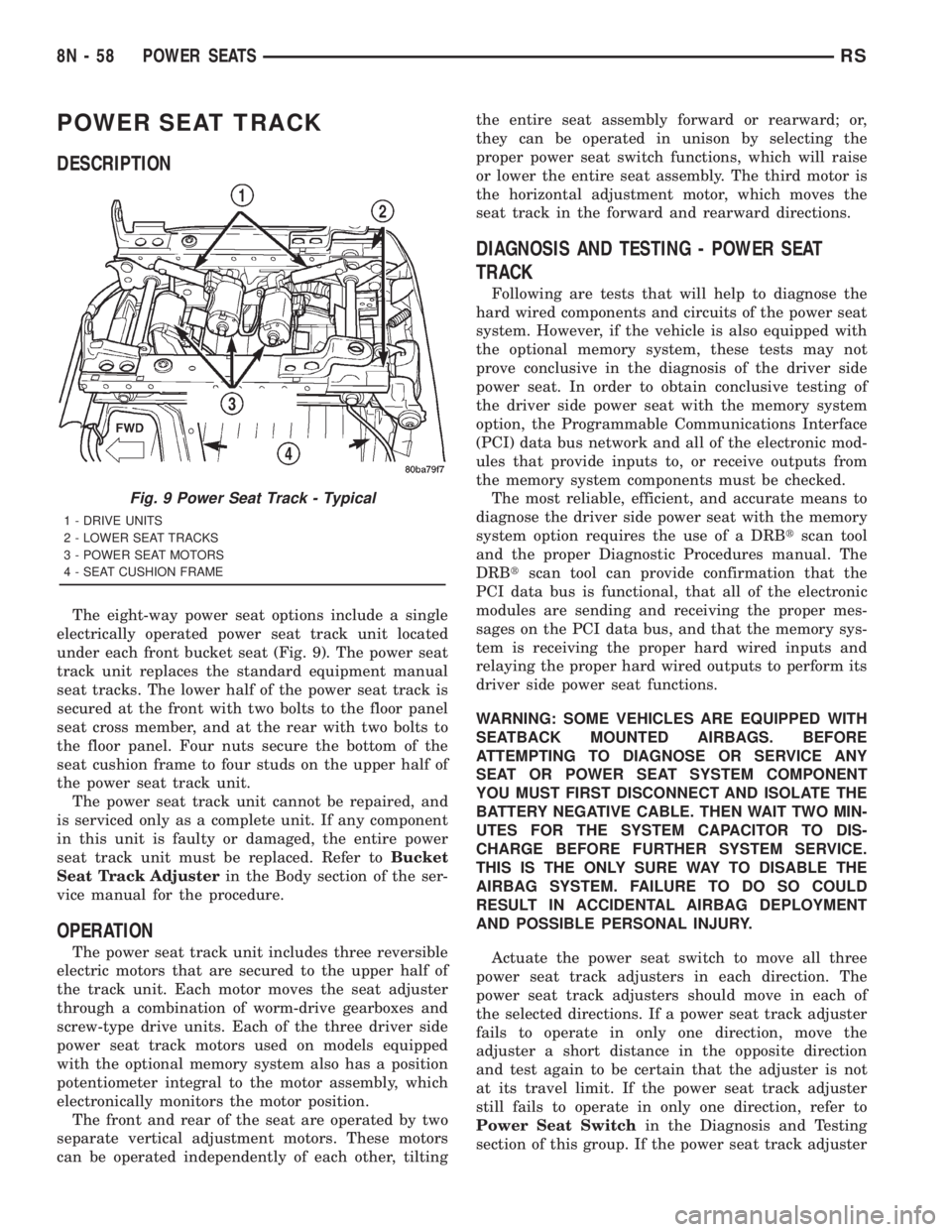
under each front bucket seat (Fig. 9). The power seat
track unit replaces the standard equipment manual
seat tracks. The lower half of the power seat track is
secured at the front with two bolts to the floor panel
seat cross member, and at the rear with two bolts to
the floor panel. Four nuts secure the bottom of the
seat cushion frame to four studs on the upper half of
the power seat track unit.
The power seat track unit cannot be repaired, and
is serviced only as a complete unit. If any component
in this unit is faulty or damaged, the entire power
seat track unit must be replaced. Refer toBucket
Seat Track Adjusterin the Body section of the ser-
vice manual for the procedure.
OPERATION
The power seat track unit includes three reversible
electric motors that are secured to the upper half of
the track unit. Each motor moves the seat adjuster
through a combination of worm-drive gearboxes and
screw-type drive units. Each of the three driver side
power seat track motors used on models equipped
with the optional memory system also has a position
potentiometer integral to the motor assembly, which
electronically monitors the motor position.
The front and rear of the seat are operated by two
separate vertical adjustment motors. These motors
can be operated independently of each other, tiltingthe entire seat assembly forward or rearward; or,
they can be operated in unison by selecting the
proper power seat switch functions, which will raise
or lower the entire seat assembly. The third motor is
the horizontal adjustment motor, which moves the
seat track in the forward and rearward directions.
DIAGNOSIS AND TESTING - POWER SEAT
TRACK
Following are tests that will help to diagnose the
hard wired components and circuits of the power seat
system. However, if the vehicle is also equipped with
the optional memory system, these tests may not
prove conclusive in the diagnosis of the driver side
power seat. In order to obtain conclusive testing of
the driver side power seat with the memory system
option, the Programmable Communications Interface
(PCI) data bus network and all of the electronic mod-
ules that provide inputs to, or receive outputs from
the memory system components must be checked.
The most reliable, efficient, and accurate means to
diagnose the driver side power seat with the memory
system option requires the use of a DRBtscan tool
and the proper Diagnostic Procedures manual. The
DRBtscan tool can provide confirmation that the
PCI data bus is functional, that all of the electronic
modules are sending and receiving the proper mes-
sages on the PCI data bus, and that the memory sys-
tem is receiving the proper hard wired inputs and
relaying the proper hard wired outputs to perform its
driver side power seat functions.
WARNING: SOME VEHICLES ARE EQUIPPED WITH
SEATBACK MOUNTED AIRBAGS. BEFORE
ATTEMPTING TO DIAGNOSE OR SERVICE ANY
SEAT OR POWER SEAT SYSTEM COMPONENT
YOU MUST FIRST DISCONNECT AND ISOLATE THE
BATTERY NEGATIVE CABLE. THEN WAIT TWO MIN-
UTES FOR THE SYSTEM CAPACITOR TO DIS-
CHARGE BEFORE FURTHER SYSTEM SERVICE.
THIS IS THE ONLY SURE WAY TO DISABLE THE
AIRBAG SYSTEM. FAILURE TO DO SO COULD
RESULT IN ACCIDENTAL AIRBAG DEPLOYMENT
AND POSSIBLE PERSONAL INJURY.
Actuate the power seat switch to move all three
power seat track adjusters in each direction. The
power seat track adjusters should move in each of
the selected directions. If a power seat track adjuster
fails to operate in only one direction, move the
adjuster a short distance in the opposite direction
and test again to be certain that the adjuster is not
at its travel limit. If the power seat track adjuster
still fails to operate in only one direction, refer to
Power Seat Switchin the Diagnosis and Testing
section of this group. If the power seat track adjuster
Fig. 9 Power Seat Track - Typical
1 - DRIVE UNITS
2 - LOWER SEAT TRACKS
3 - POWER SEAT MOTORS
4 - SEAT CUSHION FRAME
8N - 58 POWER SEATSRS
Page 3060 of 4284
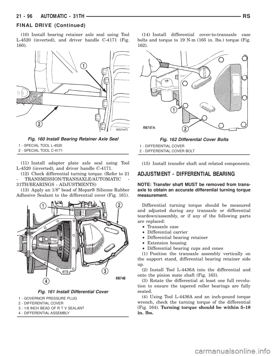
(10) Install bearing retainer axle seal using Tool
L-4520 (inverted), and driver handle C-4171 (Fig.
160).
(11) Install adapter plate axle seal using Tool
L-4520 (inverted), and driver handle C-4171.
(12) Check differential turning torque. (Refer to 21
- TRANSMISSION/TRANSAXLE/AUTOMATIC -
31TH/BEARINGS - ADJUSTMENTS)
(13) Apply an 1/8º bead of Moparž Silicone Rubber
Adhesive Sealant to the differential cover (Fig. 161).(14) Install differential cover-to-transaxle case
bolts and torque to 19 N´m (165 in. lbs.) torque (Fig.
162).
(15) Install transfer shaft and related components.
ADJUSTMENT - DIFFERENTIAL BEARING
NOTE: Transfer shaft MUST be removed from trans-
axle to obtain an accurate differential turning torque
measurement.
Differential turning torque should be measured
and adjusted during any transaxle or differential
teardown/assembly, or if any of the following parts
are replaced:
²Transaxle case
²Differential carrier
²Differential bearing retainer
²Extension housing
²Differential bearing cups and cones
(1) Position the transaxle assembly vertically on
the support stand, differential bearing retainer side
up.
(2) Install Tool L-4436A into the differential and
onto the pinion mate shaft (Fig. 163).
(3) Rotate the differential at least one full revolu-
tion to ensure the tapered roller bearings are fully
seated.
(4) Using Tool L-4436A and an inch-pound torque
wrench, check the turning torque of the differential
(Fig. 164).Turning torque should be within 5±18
in. lbs.
Fig. 160 Install Bearing Retainer Axle Seal
1 - SPECIAL TOOL L-4520
2 - SPECIAL TOOL C-4171
Fig. 161 Install Differential Cover
1 - GOVERNOR PRESSURE PLUG
2 - DIFFERENTIAL COVER
3 - 1/8 INCH BEAD OF R T V SEALANT
4 - DIFFERENTIAL ASSEMBLY
Fig. 162 Differential Cover Bolts
1 - DIFFERENTIAL COVER
2 - DIFFERENTIAL COVER BOLT
21 - 96 AUTOMATIC - 31THRS
FINAL DRIVE (Continued)
Page 3096 of 4284
ADJUSTMENT - OUTPUT SHAFT BEARING
(1) With output shaft gear removed, install a 13.65
mm (0.537 inch) and a 1.34 mm (0.053 inch) gauging
shims on the planetary rear annulus gear hub using
grease to hold the shims in place. The 13.65 mm
shim has a larger inside diameter and must be
installed over the output shaft first. The 1.34 mm
shim pilots on the output shaft.
(2) Install output shaft gear and bearing assembly,
torque to 271 N´m (200 ft. lbs.).
(3) To measure bearing end play:
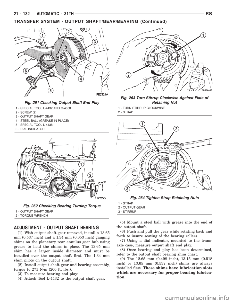
(4) Attach Tool L-4432 to the output shaft gear.(5) Mount a steel ball with grease into the end of
the output shaft.
(6) Push and pull the gear while rotating back and
forth to insure seating of the bearing rollers.
(7) Using a dial indicator, mounted to the trans-
axle case, measure output shaft end play.
(8) Once bearing end play has been determined,
refer to the output shaft bearing shim chart.
(9) The 12.65 mm (0.498 inch), 13.15 mm (0.518
inch) or 13.65 mm (0.537 inch) shims are always
installed first.These shims have lubrication slots
which are necessary for proper bearing lubrica-
tion.
Fig. 261 Checking Output Shaft End Play
1 - SPECIAL TOOL L-4432 AND C-4658
2 - SCREW (2)
3 - OUTPUT SHAFT GEAR
4 - STEEL BALL (GREASE IN PLACE)
5 - SPECIAL TOOL L-4438
6 - DIAL INDICATOR
Fig. 262 Checking Bearing Turning Torque
1 - OUTPUT SHAFT GEAR
2 - TORQUE WRENCH
Fig. 263 Turn Stirrup Clockwise Against Flats of
Retaining Nut
1 - TURN STIRRUP CLOCKWISE
2 - STRAP
Fig. 264 Tighten Strap Retaining Nuts
1 - STRAP
2 - OUTPUT GEAR
3 - STIRRUP
21 - 132 AUTOMATIC - 31THRS
TRANSFER SYSTEM - OUTPUT SHAFT/GEAR/BEARING (Continued)
Page 3106 of 4284
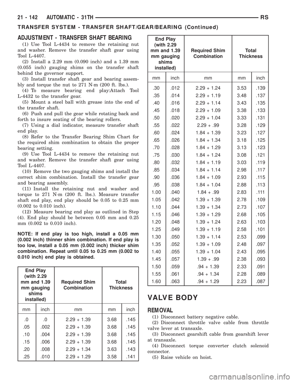
ADJUSTMENT - TRANSFER SHAFT BEARING
(1) Use Tool L-4434 to remove the retaining nut
and washer. Remove the transfer shaft gear using
Tool L-4407.
(2) Install a 2.29 mm (0.090 inch) and a 1.39 mm
(0.055 inch) gauging shims on the transfer shaft
behind the governor support.
(3) Install transfer shaft gear and bearing assem-
bly and torque the nut to 271 N´m (200 ft. lbs.).
(4) To measure bearing end play:Attach Tool
L-4432 to the transfer gear.
(5) Mount a steel ball with grease into the end of
the transfer shaft.
(6) Push and pull the gear while rotating back and
forth to insure seating of the bearing rollers.
(7) Using a dial indicator, measure transfer shaft
end play.
(8) Refer to the Transfer Bearing Shim Chart for
the required shim combination to obtain the proper
bearing setting.
(9) Use Tool L-4434 to remove the retaining nut
and washer. Remove the transfer shaft gear using
Tool L-4407.
(10) Remove the two gauging shims and install the
correct shim combination. Install the transfer gear
and bearing assembly.
(11) Install the retaining nut and washer and
torque to 271 N´m (200 ft. lbs.). Measure transfer
shaft end play, end play should be 0.05 to 0.25 mm
(0.002 to 0.010 inch).
(12) Measure bearing end play as outlined in Step
(4). End play should be between 0.05 mm and 0.25
mm (0.002 to 0.010 inch).
NOTE: If end play is too high, install a 0.05 mm
(0.002 inch) thinner shim combination. If end play is
too low, install a 0.05 mm (0.002 inch) thicker shim
combination. Repeat until 0.05 to 0.25 mm (0.002 to
0.010 inch) end play is obtained.
End Play
(with 2.29
mm and 1.39
mm gauging
shims
installed)Required Shim
CombinationTotal
Thickness
mm inch mm mm inch
.0 .0 2.29 + 1.39 3.68 .145
.05 .002 2.29 + 1.39 3.68 .145
.10 .004 2.29 + 1.39 3.68 .145
.15 .006 2.29 + 1.39 3.68 .145
.20 .008 2.29 + 1.34 3.63 .143
.25 .010 2.29 + 1.29 3.58 .141
End Play
(with 2.29
mm and 1.39
mm gauging
shims
installed)Required Shim
CombinationTotal
Thickness
mm inch mm mm inch
.30 .012 2.29 + 1.24 3.53 .139
.35 .014 2.29 + 1.19 3.48 .137
.40 .016 2.29 + 1.14 3.43 .135
.45 .018 2.29 + 1.09 3.38 .133
.50 .020 2.29 + 1.04 3.33 .131
.55 .022 2.29 + .99 3.28 .129
.60 .024 1.84 + 1.39 3.23 .127
.65 .026 1.84 + 1.34 3.18 .125
.70 .028 1.84 + 1.29 3.13 .123
.75 .030 1.84 + 1.24 3.08 .121
.80 .032 1.84 + 1.19 3.03 .119
.85 .034 1.84 + 1.14 2.98 .117
.90 .036 1.84 + 1.09 2.93 .115
.95 .038 1.84 + 1.04 2.88 .113
1.00 .040 1.84 + .99 2.83 .111
1.05 .042 1.39 + 1.39 2.78 .109
1.10 .044 1.39 + 1.34 2.73 .107
1.15 .046 1.39 + 1.29 2.68 .105
1.20 .048 1.39 + 1.24 2.63 .103
1.25 .049 1.39 + 1.19 2.58 .101
1.30 .050 1.39 + 1.14 2.53 .099
1.35 .052 1.39 + 1.09 2.48 .097
1.40 .055 1.39 + 1.04 2.43 .095
1.45 .057 1.39 + .99 2.38 .093
1.50 .059 .94 + 1.39 2.33 .091
1.55 .061 .94 + 1.34 2.28 .089
1.60 .063 .94 + 1.29 2.23 .087
VALVE BODY
REMOVAL
(1) Disconnect battery negative cable.
(2) Disconnect throttle valve cable from throttle
valve lever at transaxle.
(3) Disconnect gearshift cable from gearshift lever
at transaxle.
(4) Disconnect torque converter clutch solenoid
connector.
(5) Raise vehicle on hoist.
21 - 142 AUTOMATIC - 31THRS
TRANSFER SYSTEM - TRANSFER SHAFT/GEAR/BEARING (Continued)
Page 3207 of 4284
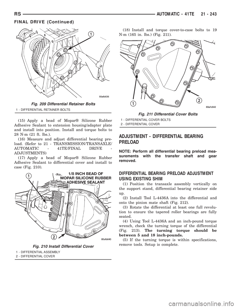
(15) Apply a bead of Moparž Silicone Rubber
Adhesive Sealant to extension housing/adapter plate
and install into position. Install and torque bolts to
28 N´m (21 ft. lbs.).
(16) Measure and adjust differential bearing pre-
load. (Refer to 21 - TRANSMISSION/TRANSAXLE/
AUTOMATIC - 41TE/FINAL DRIVE -
ADJUSTMENTS)
(17) Apply a bead of Moparž Silicone Rubber
Adhesive Sealant to differential cover and install to
case (Fig. 210).(18) Install and torque cover-to-case bolts to 19
N´m (165 in. lbs.) (Fig. 211).
ADJUSTMENT - DIFFERENTIAL BEARING
PRELOAD
NOTE: Perform all differential bearing preload mea-
surements with the transfer shaft and gear
removed.
DIFFERENTIAL BEARING PRELOAD ADJUSTMENT
USING EXISTING SHIM
(1) Position the transaxle assembly vertically on
the support stand, differential bearing retainer side
up.
(2) Install Tool L-4436A into the differential and
onto the pinion mate shaft (Fig. 212).
(3) Rotate the differential at least one full revolu-
tion to ensure the tapered roller bearings are fully
seated.
(4) Using Tool L-4436A and an inch-pound torque
wrench, check the turning torque of the differential
(Fig. 213).The turning torque should be
between 5 and 18 inch-pounds.
(5) If the turning torque is within specifications,
remove tools. Setup is complete.
Fig. 209 Differential Retainer Bolts
1 - DIFFERENTIAL RETAINER BOLTS
Fig. 210 Install Differential Cover
1 - DIFFERENTIAL ASSEMBLY
2 - DIFFERENTIAL COVER
Fig. 211 Differential Cover Bolts
1 - DIFFERENTIAL COVER BOLTS
2 - DIFFERENTIAL COVER
RSAUTOMATIC - 41TE21 - 243
FINAL DRIVE (Continued)
Page 3209 of 4284
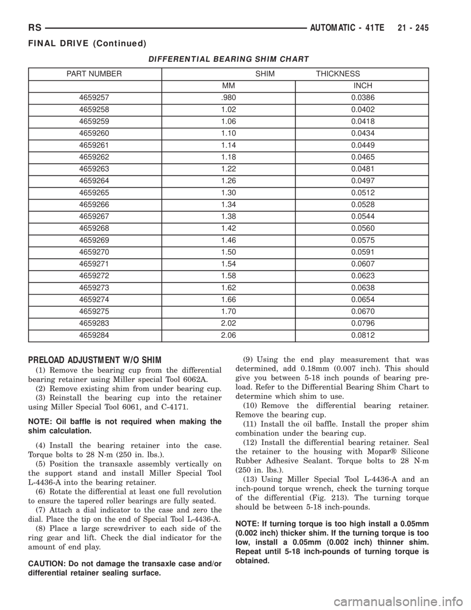
DIFFERENTIAL BEARING SHIM CHART
PART NUMBER SHIM THICKNESS
MM INCH
4659257 .980 0.0386
4659258 1.02 0.0402
4659259 1.06 0.0418
4659260 1.10 0.0434
4659261 1.14 0.0449
4659262 1.18 0.0465
4659263 1.22 0.0481
4659264 1.26 0.0497
4659265 1.30 0.0512
4659266 1.34 0.0528
4659267 1.38 0.0544
4659268 1.42 0.0560
4659269 1.46 0.0575
4659270 1.50 0.0591
4659271 1.54 0.0607
4659272 1.58 0.0623
4659273 1.62 0.0638
4659274 1.66 0.0654
4659275 1.70 0.0670
4659283 2.02 0.0796
4659284 2.06 0.0812
PRELOAD ADJUSTMENT W/O SHIM
(1) Remove the bearing cup from the differential
bearing retainer using Miller special Tool 6062A.
(2) Remove existing shim from under bearing cup.
(3) Reinstall the bearing cup into the retainer
using Miller Special Tool 6061, and C-4171.
NOTE: Oil baffle is not required when making the
shim calculation.
(4) Install the bearing retainer into the case.
Torque bolts to 28 N´m (250 in. lbs.).
(5) Position the transaxle assembly vertically on
the support stand and install Miller Special Tool
L-4436-A into the bearing retainer.
(6)
Rotate the differential at least one full revolution
to ensure the tapered roller bearings are fully seated.
(7)Attach a dial indicator to the case and zero the
dial. Place the tip on the end of Special Tool L-4436-A.
(8) Place a large screwdriver to each side of the
ring gear and lift. Check the dial indicator for the
amount of end play.
CAUTION: Do not damage the transaxle case and/or
differential retainer sealing surface.(9) Using the end play measurement that was
determined, add 0.18mm (0.007 inch). This should
give you between 5-18 inch pounds of bearing pre-
load. Refer to the Differential Bearing Shim Chart to
determine which shim to use.
(10) Remove the differential bearing retainer.
Remove the bearing cup.
(11) Install the oil baffle. Install the proper shim
combination under the bearing cup.
(12) Install the differential bearing retainer. Seal
the retainer to the housing with Moparž Silicone
Rubber Adhesive Sealant. Torque bolts to 28 N´m
(250 in. lbs.).
(13) Using Miller Special Tool L-4436-A and an
inch-pound torque wrench, check the turning torque
of the differential (Fig. 213). The turning torque
should be between 5-18 inch-pounds.
NOTE: If turning torque is too high install a 0.05mm
(0.002 inch) thicker shim. If the turning torque is too
low, install a 0.05mm (0.002 inch) thinner shim.
Repeat until 5-18 inch-pounds of turning torque is
obtained.
RSAUTOMATIC - 41TE21 - 245
FINAL DRIVE (Continued)
Page 3230 of 4284
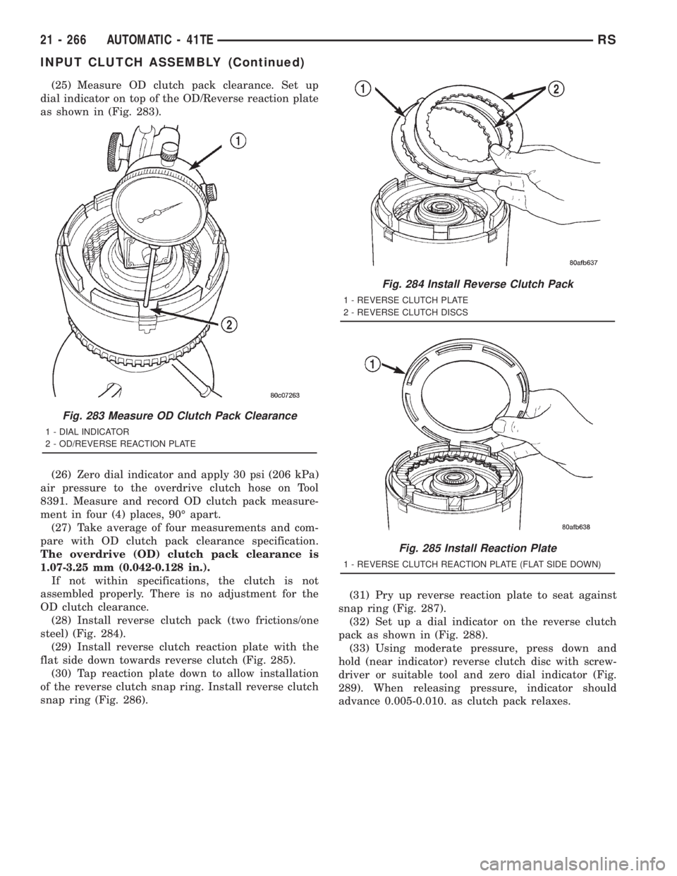
(25) Measure OD clutch pack clearance. Set up
dial indicator on top of the OD/Reverse reaction plate
as shown in (Fig. 283).
(26) Zero dial indicator and apply 30 psi (206 kPa)
air pressure to the overdrive clutch hose on Tool
8391. Measure and record OD clutch pack measure-
ment in four (4) places, 90É apart.
(27) Take average of four measurements and com-
pare with OD clutch pack clearance specification.
The overdrive (OD) clutch pack clearance is
1.07-3.25 mm (0.042-0.128 in.).
If not within specifications, the clutch is not
assembled properly. There is no adjustment for the
OD clutch clearance.
(28) Install reverse clutch pack (two frictions/one
steel) (Fig. 284).
(29) Install reverse clutch reaction plate with the
flat side down towards reverse clutch (Fig. 285).
(30) Tap reaction plate down to allow installation
of the reverse clutch snap ring. Install reverse clutch
snap ring (Fig. 286).(31) Pry up reverse reaction plate to seat against
snap ring (Fig. 287).
(32) Set up a dial indicator on the reverse clutch
pack as shown in (Fig. 288).
(33) Using moderate pressure, press down and
hold (near indicator) reverse clutch disc with screw-
driver or suitable tool and zero dial indicator (Fig.
289). When releasing pressure, indicator should
advance 0.005-0.010. as clutch pack relaxes.
Fig. 283 Measure OD Clutch Pack Clearance
1 - DIAL INDICATOR
2 - OD/REVERSE REACTION PLATE
Fig. 284 Install Reverse Clutch Pack
1 - REVERSE CLUTCH PLATE
2 - REVERSE CLUTCH DISCS
Fig. 285 Install Reaction Plate
1 - REVERSE CLUTCH REACTION PLATE (FLAT SIDE DOWN)
21 - 266 AUTOMATIC - 41TERS
INPUT CLUTCH ASSEMBLY (Continued)