Page 223 of 4770
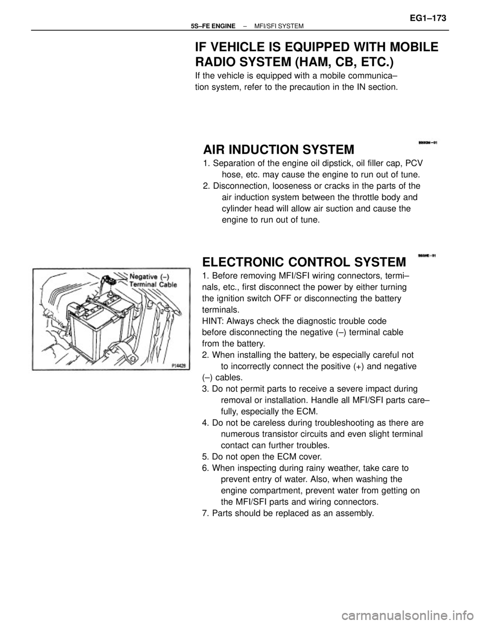
ELECTRONIC CONTROL SYSTEM
1. Before removing MFI/SFI wiring connectors, termi±
nals, etc., first disconnect the power by either turning
the ignition switch OFF or disconnecting the battery
terminals.
HINT: Always check the diagnostic trouble code
before disconnecting the negative (±) terminal cable
from the battery.
2. When installing the battery, be especially careful not
to incorrectly connect the positive (+) and negative
(±) cables.
3. Do not permit parts to receive a severe impact during
removal or installation. Handle all MFI/SFI parts care±
fully, especially the ECM.
4. Do not be careless during troubleshooting as there are
numerous transistor circuits and even slight terminal
contact can further troubles.
5. Do not open the ECM cover.
6. When inspecting during rainy weather, take care to
prevent entry of water. Also, when washing the
engine compartment, prevent water from getting on
the MFI/SFI parts and wiring connectors.
7. Parts should be replaced as an assembly.
AIR INDUCTION SYSTEM
1. Separation of the engine oil dipstick, oil filler cap, PCV
hose, etc. may cause the engine to run out of tune.
2. Disconnection, looseness or cracks in the parts of the
air induction system between the throttle body and
cylinder head will allow air suction and cause the
engine to run out of tune.
IF VEHICLE IS EQUIPPED WITH MOBILE
RADIO SYSTEM (HAM, CB, ETC.)
If the vehicle is equipped with a mobile communica±
tion system, refer to the precaution in the IN section.
± 5S±FE ENGINEMFI/SFI SYSTEMEG1±173
Page 457 of 4770
Check for open in harness and connector between IG switch and
EFI main relay, EFI main relay and body ground (See page IN±31).
Remove EFI fuse from J/B No.2.
Check continuity of EFI fuse.
Continuity
Check for open in harness and connector
between EFI main relay and battery, EFI main
relay and engine control module.Check for short in all the harness and
components connected to EFI fuse (See
attached wiring diagram). Remove under cover and finish panel.
Check continuity between terminals.
Repair or replace harness or connector.
Check ignition switch.
Replace ignition switch.
Check EFI fuse.
Switch positioncontinuity
10
AM2 Terminal
4
AM1 3
ACC6
ST27
ST19
IG2
START2
lG1
LOCK
ACC
± 5S±FE ENGINECIRCUIT INSPECTIONEG1±407
Page 459 of 4770
Remove glove compartment.
(See page EG1±234)
Measure voltage between terminal BATT of en±
gine control module connector and body ground.
Voltage: 9 ±14 V
Check voltage between terminal BATT of engine control module
connector and body ground.
Are the diagnostic trouble codes still in the memory when the
ignition switch is turned OFF?
Check and repair harness or connector
between engine control module and EN
fuse, EFI fuse and battery. Remove EFI fuse from J/B No.2.
Check continuity of EFI fuse.
Continuity
Check for short in all the harness and
components connected to EFI fuse
(See attached wiring diagram).
Proceed to next circuit inspection shown on
matrix chart (See page EG1±327).Check and replace engine control module.
INSPECTION PROCEDURE
Check EFI fuse.
Others
YES
± 5S±FE ENGINECIRCUIT INSPECTIONEG1±409
Page 480 of 4770

DIAGNOSTIC CHART
HINT: If terminals TE1 and TE2 are connected with terminal E1, diagnostic trouble code is not
output or test mode is not activated.
Even though terminal TE1 is not connected with terminal E1, the malfunction indicator lamp
blinks.
For the above phenomenon, the likely cause is an open or short in the wire harness, or
malfunction inside the ECM.
CIRCUIT DESCRIPTION
Terminals TE1 and TE2 are located in the data link connector 1 and 2.
The data link connector 1 located in the engine compartment and the data link connector 2 located
in the cabin. When these terminals are connected with the E1 terminal, diagnostic trouble codes in
normal mode or test mode can be read from the malfunction indicator lamp on the combination meter.
Check for open and short in harness and
connector between data link connector 1, 2
and ECM.Check continuity between terminal E1 and body
ground.
TE1 TE2 Terminal Circuit
Repair or replace harness or connector.Repair or replace harness or connector. Check voltage of terminals TE1, TE2.
WIRING DIAGRAM
Check and replace ECM.Check and replace ECM.
± 5S±FE ENGINECIRCUIT INSPECTIONEG1±430
Page 587 of 4770
112BODY ELECTRICALÐACCESSORIES
2. Layout of Components
The major function of the airbag system are shown below.
3. Wiring Diagram
Page 598 of 4770

Manual Name
Pub. No.
(USA & CANADA)
�1997 Camry Repair Manual
�1997 Camry Electrical Wiring Diagram
�Camry New Car Features
(Models except USA and CANADA)
�Camry Chassis and Body Repair Manual
�5S±FE Engine Repair Manual
Supplement
�1MZ±FE Engine Repair Manual
Supplement
�Camry Electrical Wiring Manual
�Camry NewCar Features
(All Countries)
�Fundamental Painting Procedures
�Fundamental Body Repair ProceduresEWD275Y
NCF136E
BRM024E
BRM002E RM550E RM536E
RM547E RM503U
EWD280U
NCF134U Applicable models:
FOREWORD
This repair manual has been prepared to provide essential infor-
mation on body panel repair methods (including cutting and
welding operations, but excluding painting) for the
TOYOTA CAMRY.
SXV20 series
MCV20 series
This manual consists of body repair methods, exploded dia-
grams and illustrations of the body components and other infor-
mation relating to body panel replacement such as handling
precautions, etc. However, it should be noted that the front fend-
ers of the TOYOTA model is bolted on and require no welding.
When repairing, don't cut and join areas that are not shown in
this manual. Only work on the specified contents to maintain
body strength.
Body construction will sometimes differ depending on specifica-
tions and country of destination. Therefore, please keep in mind
that the information contained herein is based on vehicles for
general destinations.
For the repair procedures and specifications other than colli-
sion±damaged body components of the TOYOTA CAMRY refer
to the following repair manuals.
If you require the above manuals, please contact your TOYOTA
Dealer.
All information contained in this manual is the most up±to±date
at the time of publication. However, specifications and proce-
dures are subject to change without prior notice.
TOYOTA MOTOR CORPORATION
Page 733 of 4770

CAMRY ± NEW FEATURES
150NF118
BatteryIgnition Switch
EFI
Relay
Transponder
Key Coil
Transponder
Key AmplifierECMBody
ECU
DLC1
150NF119
Transponder Chip
24
3. Wiring Diagram
4. Construction
The engine immobiliser system consists of the transponder key (ignition key), transponder key coil, trans-
ponder key amplifier, and ECM.
Transponder Key (Ignition Key)
A transponder chip is embedded in the grip of the
ignition key. Each transponder chip contains an
individual transponder key-code (ID code). The
key does not need an internal battery to transmit
a key code.
Transponder Key Coil and Transponder Key Amplifier
The transponder key coil is a ring-shaped coil installed around the ignition key cylinder. The transponder
key amplifier is installed in the back of the key cylinder.
An electrical power circuit to provide power to the transponder key coil has been enclosed in the amplifier.
ECM
The control circuit of the engine immobiliser system has been integrated inside the ECM. As a result, the
time has been reduced taken for the engine to start in case of mismatching key code thus improving the
system's theft deterrent performance.
A maximum of 10 different transponder key codes (master key: 7 types, sub key: 3 types) can be registered
in the ECM.
Page 814 of 4770
'99camry U
48
CAUTION
SRS side airbags inflate with consid-
erable force. To avoid potential death
or serious injury during inflation of a
side airbag, Toyota strongly recom-
mends that the driver and front pas-
senger;
�Wear their seat belt
�Remain properly seated with their
back against the seat at all times.
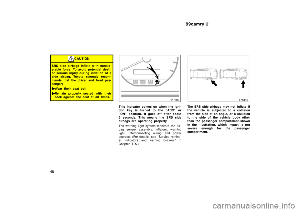
This indicator comes on when the igni-
tion key is turned to the ºACCº or
ºONº position. It goes off after about
6 seconds. This means the SRS side
airbags are operating properly.
The warning light system monitors the air-
bag sensor assembly, inflators, warning
light, interconnecting wiring and power
sources. (For details, see ºService remind-
er indicators and warning buzzersº in
Chapter 1±5.)The SRS side airbags may not inflate if
the vehicle is subjected to a collision
from the side at an angle, or a collision
to the side of the vehicle body other
than the passenger compartment shown
in the illustration, which impact is not
severe enough for the passenger
compartment.