Page 1091 of 4770

Rear
Model Code
Front mm (in.)
Rear mm (in.)4-Door Sedan
ItemArea
Body Type
Vehicle Grade
OverallLength mm (in.)
Width mm (in.)
Height* mm (in.)
Wheel Base mm (in.)
Tread")
APPENDIX
Curb to Curb m (ft.)
Rear
Model Code
Front mm (in.)
Rear mm (in.)4-Door Sedan
ItemArea
Body Type
Vehicle Grade
OverallLength mm (in.)
Width mm (in.)
Height* mm (in.)
Wheel Base mm (in.)
Tread
Rear mm (in.)
Effective Head Room
Front mm (in.)
Overhang
Min. Running Ground Clearance mm (in.)
Angle of Approach degrees
Angle of Departure degrees
Curb Weight
Gross Vehicle WeightFront kg (lb)
Rear kg (lb)
Total kg (lb)
Front kg (lb)
Rear kg (lb)
Total kg (lb)
Fuel Tank Capacity (US.gal., Imp. gal)
Max. Speed km / h (mph)
Max. Cruising Speed km / h (mph)
Acceleration
Wall to Wall m (ft.) 0 to 100 km/h sec.
Valve Mechanism
Brake Type
Parking Brake Type
Brake Booster Type and Size in.
Proportioning Valve Type
Suspension Type
Stabilizer Bar
Steering Gear Type
Steering Gear Ratio (Overall)
Power Steering TypeFront
Front
Rear Front
Rear
5
10
15
20
25
30
35
40
45
50
55
60
65
70
Major Dimensions & Vehicle Weights Performance Chassis
U.S.A.
Shoulder Room
Front mm (in.)
Rear mm (in.)
Front mm (in.)
Rear mm (in.)
Front mm (in.)
Rear mm (in.) Effective Leg Room
Turning Diameter
(Outside Front)0 to 400 m sec.
Engine
Electrical
Engine Type
Bore � Stroke mm (in.)
Differential Gear Ratio (Final) Counter Gear RatioIn Fifth
In Reverse Transmission Gear
RatioIn Third
In Fourth In First
In Second
Clutch Type
Transaxle TypeStarter Output kW Generator Output Watts Battery Capacity (5HR) Voltage & Amp. hr. Carburetor Type Compression Ratio Displacement cm
3 (cu.in.)
Max. Torque (SAE-NET) N´m/rpm (lb-ft@rpm) Research Octane No. RON
Max. Output (SAE-NET) kW/rpm (HP@rpm)
Engine
3rd Gear km/h (mph)
4th Gear km/h (mph) 1st Gear km/h (mph)
2nd Gear km/h (mph)
Max. Permissible
Speed
Luggage Compartment Capacity
28
MAJOR TECHNICAL SPECIFICATIONS
LE
SXV23L-AEPNCA
4785 (188.4)
1780 (70.1)
1420 (55.9)
2670 (105.1)
1545 (60.8)
1520 (59.8)
980 (38.6)
940 (37.0)
1102 (43.4)
901 (35.5)
1427 (56.2)
1425 (56.1)
970 (38.2)
1140 (44.9)
130 (5.1)
165
165
860 (1896)
595 (1312)
1455 (3208)
970 (2140)
950 (2095)
1920 (4235)
135 (35.7, 29.2)*1, 43 (11.4. 9.5)*2
0.332 m3 *3, 8.921 ft3
*4
180 (112)
Ð
Ð
Ð
66 (41)
119 (74)
Ð
Ð
11.9 (39.0)
11.4 (37.4)
5S-FNE
16-Valve, DOHC
87.0 � 91.0 (3.43 � 3.58)
2164 (132.0)
11.0 : 1
SFI
130
88/5200 (118/5200)
178/2400 (131/2400)
12 ± 55
960
1.4
Ð
A140E
2.810
1.549
1.000
0.706
Ð
2.296
0.945
4.176
Ventilated Disc
L.T. Drum
Drum
Tandem 8º + 9º
Dual-P Valve
MacPherson Strut
MacPherson Strut
STD
STD
Rack and Pinion
17.4 : 1
Integral Type
*: Unladed Vehicle
*
1: Water Volume
*2: Equivalent Gasoline Capacity
*3: VDA
*4: SAE Suitcase
Page 1880 of 4770
AUTOMATIC TRANSAXLEVALVE BODY ±
AX±84
10. INSTALL LOWER VALVE BODY COVER GASKETS
AND NO.2 PLATE
Position a new gasket and plate and then another new
gasket.
HINT: Both gaskets are identical.
11. INSTALL LOWER VALVE BODY COVER
(a) Position the lower valve body cover.
(b) Install and finger tighten the 5 bolts.
HINT: Each bolt length is indicated below.
Bolt length
Bolt A: 47 mm (1.850 in.)
Bolt B: 14 mm (0.551 in.)
12. INSTALL PRESSURE RELIEF VALVE
13. TIGHTEN BOLTS OF UPPER AND LOWER VALVE BO-
DIES
(a) Tighten the 16 bolts in the lower valve body.
Torque: 6.6 N´m (67 kgf´cm, 58 in.´lbf)
(b) Tighten the 3 bolts in the upper valve body.
Torque: 6.6 N´m (67 kgf´cm, 58 in.´lbf)
14. INSTALL B0 ACCUMULATOR ASSEMBLY
(a) Coat new O±rings with ATF and install them to the piston.
(b) Install the spring and piston into the cylinder.
Spring dimensions
mm (in.)
ColorFree lengthCoil outer diameter
Inner White47.5 (1.870)18.9 (0.744)
Outer None16.3 (0.642)20.7 (0.815)
Page 1916 of 4770
AUTOMATIC TRANSAXLECOMPONENT PARTS INSTALLATION ±
AX±120
(b) Using SST, measure the piston stroke while applying and
releasing compressed air (392±785 kPa, 4±8 kgf/cm
2,
57±114 psi).
SST 09240±00020
Piston stroke:
2.0±3.5 mm (0.079±0.138 in.)
If the stroke is more than specified, replace the piston rod
with a longer one.
Piston rod length:
95.2 mm (3.748 in.)
96.3 mm (3.791 in.)
If the still more than standard value, replace the brake
band with a new one.
HYDRAULIC CONTROL UNIT INSTALLATION
1. INSTALL ACCUMULATOR PISTONS AND SPRINGS
(a) Install the new O±rings to the pistons.
(b) Install the springs and pistons into the bores.
Spring dimensions
mm (in.)
Spring ColorFree length
C2Yellow/Purple51.8 (2.039)
B2None88.2 (3.473)
B2None70.3 (2.767)
C1None73.6 (2.898)
(c) Place the cover with a new gasket and gradually tighten
the bolts a little at a time in sequence.
Torque: 10 N´m (100 kgf´cm, 7 ft´lbf)
AX0U3±02
Page 3497 of 4770
CYLINDER BLOCK
EM±105
1277 Author�: Date�:
(b) Using a micrometer, measure the piston diameter at right
angle")
A07352
20.5 mm
S01546
SST
S05573
Cut Position
Pry
S05572
SST
± ENGINE MECHANICAL (5S±FE)CYLINDER BLOCK
EM±105
1277 Author�: Date�:
(b) Using a micrometer, measure the piston diameter at right
angles to the piston pin center line, 20.5 mm (0.807 in.)
from the piston head.
(c) Calculate the amount of each cylinder is to be rebored as
follows:
Size to be rebored = P + C ± H
P = Piston diameter
C = Piston oil clearance
0.175 ± 0.195 mm (0.0068 ± 0.0076 in.)
H = Allowance for honing
0.02 mm (0.0008 in.) or less
(d) Bore and hone the cylinders to calculated dimensions.
Maximum honing: 0.02 mm (0.0008 in.)
NOTICE:
Excess honing will destroy the finished roundness.
3. REPLACE CRANKSHAFT FRONT OIL SEAL
HINT:
There are 2 methods ((a) and (b)) to replace the oil seal.
(a) If the oil pump is removed from the cylinder block:
(1) Using a screwdriver and hammer, tap out the oil
seal.
(2) Using SST and a hammer, tap in a new oil seal until
its surface is flush with the oil pump body edge.
SST 09226±10010
(3) Apply MP grease to the oil seal lip.
(b) If the oil pump is installed to the cylinder block:
(1) Using a knife, cut off the oil seal lip.
(2) Using a screwdriver, pry out the oil seal.
NOTICE:
Be careful not to damage the crankshaft. Tape the screw-
driver tip.
(3) Apply MP grease to a new oil seal lip.
(4) Using SST and a hammer, tap in the oil seal until its
surface is flush with the oil pump body edge.
SST 09226±10010
Page 3680 of 4770
N20620
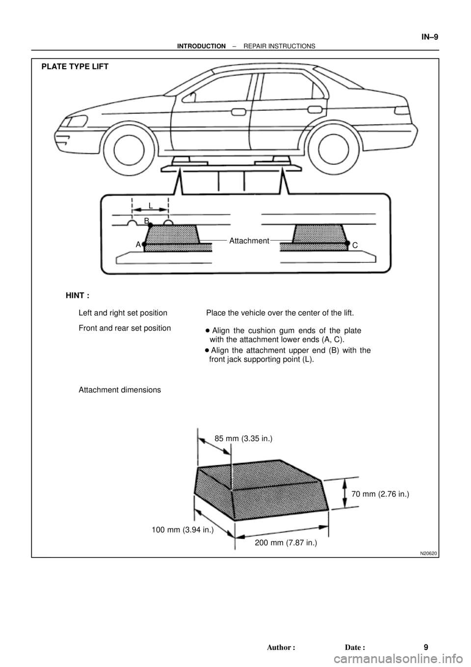
PLATE TYPE LIFT
L
B
AAttachment
C
HINT :
Left and right set position
Front and rear set positionPlace the vehicle over the center of the lift.
� Align the cushion gum ends of the plate
with the attachment lower ends (A, C).
� Align the attachment upper end (B) with the
front jack supporting point (L).
Attachment dimensions
85 mm (3.35 in.)
100 mm (3.94 in.)70 mm (2.76 in.)
200 mm (7.87 in.)
± INTRODUCTIONREPAIR INSTRUCTIONS
IN±9
9 Author�: Date�:
Page 4198 of 4770
Width
± SUPPLEMENTAL RESTRAINT SYSTEMSTEERING WHEEL PAD AND SPIRAL CABLE
RS±23
2168 Author�: Date�:
(e) Install the SST.
CAUTION:
Pl")
H06696
SST
H00401Weight
x y
y
R04211
Inner Diam.
Tires
(3 or More)Width
± SUPPLEMENTAL RESTRAINT SYSTEMSTEERING WHEEL PAD AND SPIRAL CABLE
RS±23
2168 Author�: Date�:
(e) Install the SST.
CAUTION:
Place the disc wheel on the level ground.
(1) Connect the connector of SST to the steering wheel
pad connector.
SST 09082±00700
NOTICE:
To avoid damaging the SST connector and wire harness,
do not lock the secondary lock of the twin lock. Also, se-
cure some slack for the SST wire harness inside the disc
wheel.
(2) Move the SST to at least 10 m (33 ft) away from the
steering wheel pad tied down on the disc wheel.
(f) Cover the steering wheel pad with a cardboard box or
tires.
�Covering method using a cardboard box:
Cover the steering wheel pad with the cardboard
box and weight the cardboard box down in 4 places
with at least 190 N (20 kg, 44 lb).
Size of cardboard box:
Must exceed the following dimensions:
x= 460 mm (18.11 in.)
When dimension of the cardboard box exceeds the di-
ameter of the disc wheel with tire to which the steer-
ing wheel pad is tied
x= 460 mm (18.11 in.) + width of tire
y= 650 mm (25.59 in.)
NOTICE:
If a cardboard box smaller than the specified size is used,
the cardboard box will be broken by the shock from the air-
bag deployment.
�Covering method using tires:
Place at least 3 tires without disc wheel on top of the
disc wheel with tire to which the steering wheel pad
is tied.
Tire size: Must exceed the following dimensions±
Width: 185 mm (7.87 in.)
Inner diameter: 360 mm (14.17 in.)
Page 4209 of 4770

W03519
L
M
W03652
2 times or more
R08582
Width
Inner
Diam. RS±34
± SUPPLEMENTAL RESTRAINT SYSTEMFRONT PASSENGER AIRBAG ASSEMBLY
2179 Author�: Date�:
CAUTION:
If the front passenger airbag assembly is tied down with
too thin wire harness, it may snap. This is highly danger-
ous. Always use a wire harness which is at least 1.25 mm
2
(0.0019 in.2).
HINT:
To calculate the square of the stripped wire harness section:
Square = 3.14 X (Diameter)
2 divided by 4
(1) Install the 2 bolts with washers in the 2 bolt holes in
the front passenger airbag assembly,
Bolt:
L: 35.0 mm (1.387 in.)
M: 6.0 mm (0.236 in.)
Pitch: 1.0 mm (0.039 in.)
NOTICE:
�Tighten the bolts by hand until the bolts become diffi-
cult to turn.
�Do not tighten the bolts too much.
(2) Using 3 wire harness, wind the wire harness at least
2 times each around the bolts installed on the front
passenger airbag assembly.
(3) Position the front passenger airbag assembly in-
side the tire with the airbag deployment side facing
inside.
Tire size: Must exceed the following dimensions±
Width: 185 mm (7.28 in.)
Inner diameter: 360 mm (14.17 in.)
CAUTION:
�Make sure that the wire harness is tight. It is very dan-
gerous if looseness in the wire harness results in the
front passenger airbag assembly coming free due to
the shock from the airbag deploying.
�Always tie down the front passenger airbag assembly
with the airbag deployment side facing inside.
NOTICE:
The tire will be marked by the airbag deployment, so use a
redundant tire.
Page 4220 of 4770
H01333
H01334
H08326
Inner
Diam.Width
AB0158
SSTBattery
± SUPPLEMENTAL RESTRAINT SYSTEMSIDE AIRBAG ASSEMBLY (TMC Made)
RS±45
2190 Author�: Date�:
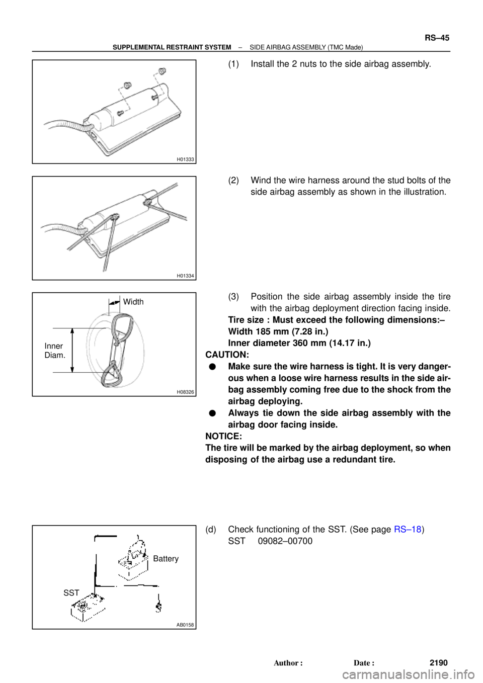
(1) Install the 2 nuts to the side airbag assembly.
(2) Wind the wire harness around the stud bolts of the
side airbag assembly as shown in the illustration.
(3) Position the side airbag assembly inside the tire
with the airbag deployment direction facing inside.
Tire size : Must exceed the following dimensions:±
Width 185 mm (7.28 in.)
Inner diameter 360 mm (14.17 in.)
CAUTION:
�Make sure the wire harness is tight. It is very danger-
ous when a loose wire harness results in the side air-
bag assembly coming free due to the shock from the
airbag deploying.
�Always tie down the side airbag assembly with the
airbag door facing inside.
NOTICE:
The tire will be marked by the airbag deployment, so when
disposing of the airbag use a redundant tire.
(d) Check functioning of the SST. (See page RS±18)
SST 09082±00700

 Using SST, measure the piston stroke while applying and
releasing compressed air (392±785 kPa, 4±8 kgf/cm
2,
57±114 psi).
SST 09240±0")