Page 4593 of 4770

PROGRAMMING OEM WIRELESS DOOR LOCK REMOTE TRANSMITTERS ± EL008±98 December 4, 1998
Page 2 of 2
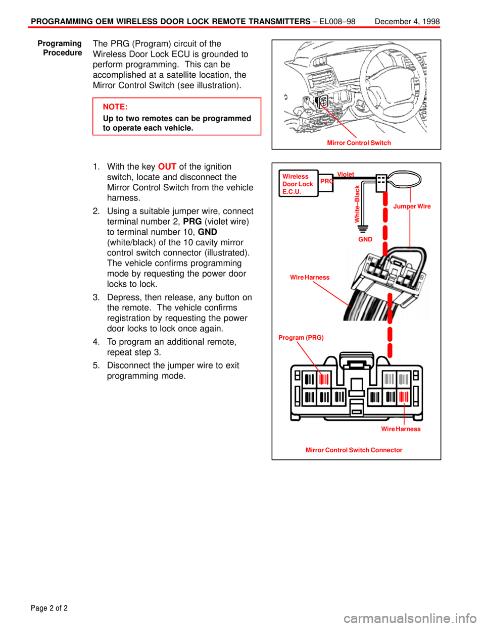
The PRG (Program) circuit of the
Wireless Door Lock ECU is grounded to
perform programming. This can be
accomplished at a satellite location, the
Mirror Control Switch (see illustration).
NOTE:
Up to two remotes can be programmed
to operate each vehicle.
1. With the key OUT of the ignition
switch, locate and disconnect the
Mirror Control Switch from the vehicle
harness.
2. Using a suitable jumper wire, connect
terminal number 2, PRG (violet wire)
to terminal number 10, GND
(white/black) of the 10 cavity mirror
control switch connector (illustrated).
The vehicle confirms programming
mode by requesting the power door
locks to lock.
3. Depress, then release, any button on
the remote. The vehicle confirms
registration by requesting the power
door locks to lock once again.
4. To program an additional remote,
repeat step 3.
5. Disconnect the jumper wire to exit
programming mode.
Mirror Control Switch
Programing
Procedure
Mirror Control Switch Connector Program (PRG)Wire HarnessJumper Wire Wireless
Door Lock
E.C.U.PRGViolet
GND
White±Black
Wire Harness
Page 4609 of 4770

DOOR MIRROR WIND NOISE ± NV007±00 March 31, 2000
Page 2 of 2
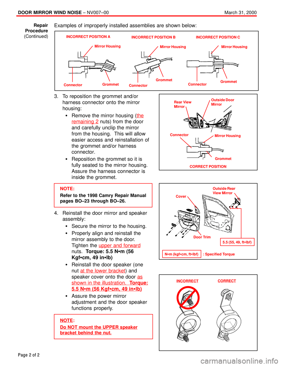
Examples of improperly installed assemblies are shown below:
ConnectorGrommet Mirror Housing
INCORRECT POSITION A
Connector
GrommetMirror Housing
INCORRECT POSITION B
Connector
GrommetMirror Housing
INCORRECT POSITION C
3. To reposition the grommet and/or
harness connector onto the mirror
housing:
�Remove the mirror housing (the
remaining 2 nuts) from the door
and carefully unclip the mirror
from the housing. This will allow
easier access and reinstallation of
the grommet and/or harness
connector.
�Reposition the grommet so it is
fully seated to the mirror housing.
Assure the harness connector is
inside the grommet.
NOTE:
Refer to the 1998 Camry Repair Manual
pages BO±23 through BO±26.
4. Reinstall the door mirror and speaker
assembly:
�Secure the mirror to the housing.
�Properly align and reinstall the
mirror assembly to the door.
Tighten the upper and forward
nuts. Torque: 5.5 N�m (56
Kgf�cm, 49 in�lb)
�Reinstall the door speaker (one
nut at the lower bracket
) and
speaker cover onto the door as
shown in the illustration. Torque:
5.5 N�m (56 Kgf�cm, 49 in�lb)
�Assure the power mirror
adjustment and the door speaker
functions properly.
NOTE:
Do NOT mount the UPPER speaker
bracket behind the nut.
Repair
Procedure
(Continued)
Rear View
Mirror
Grommet
CORRECT POSITIONOutside Door
Mirror
Mirror Housing
Connector
Cover
Door Trim
N�m (kgf�cm, ft�lbf) : Specified TorqueOutside Rear
View Mirror
5.5 (55, 49, ft�lbf)
INCORRECTCORRECT
Page 4645 of 4770

WARRANTY PARTS MARKING PROCEDURE ± PG006-03September 26, 2003
Page 2 of 3
Dealers are requested to mark the location of the failure of all warranty parts that are
listed below.
This list is not inclusive. There may be other components that can be
marked in the area of failure. All other parts that can be marked should be marked.
assist grip assy headlamps
audio (blemish) headliner
back door garnish hoses
bumper covers instrument panel safety pad sub±assy
cargo cover (retractable) Interior light assemblies and covers
carpet knobs, levers, handles
clutch disc l/pulley pump assy
clutch flywheel mirrors (side and rearview)
combination meter glass navigation or VES screens
console and components pillar garnish
cowl assy rack and pinion/power steering gear assy
cowl side trim sub±assy radiator
cupholders room partition board
cylinder head cover sub±assy rotors (mark where min. runout is exceeded or warped)
dash panel insulator assy seat covers/cushions
dashboard and trim seat tracks
disc wheel soft trim
display panels spare tire cover
door handle assy steering column cover
door moulding steering wheel
door trim panel & molding tail lamps and covers
emblems transmission oil pan
engine oil pan visor
exhaust manifold washer jar
floor and cargo mats wheel cap
gear shift knob wheels
grills
Parts
Marking
Requirement
Parts
Marking
List