Page 2639 of 4770

± DIAGNOSTICSENGINE (1MZ±FE)
DI±219
454 Author�: Date�:
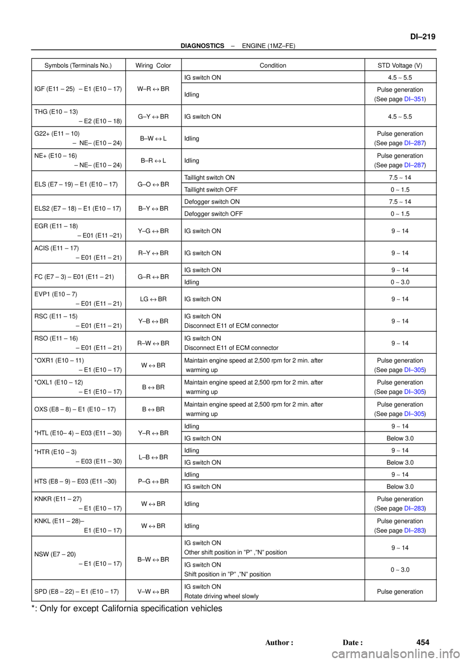
Symbols (Terminals No.)Wiring ColorConditionSTD Voltage (V)
IG switch ON4.5 ~ 5.5
IGF (E11 ± 25) ± E1 (E10 ± 17)W±R eBRIdlingPulse generation
(See page DI±351)
THG (E10 ± 13)
± E2 (E10 ± 18)G±Y eBRIG switch ON4.5 ~ 5.5
G22+ (E11 ± 10)
± NE± (E10 ± 24)B±W eLIdlingPulse generation
(See page DI±287)
NE+ (E10 ± 16)
± NE± (E10 ± 24)B±R eLIdlingPulse generation
(See page DI±287)
ELS (E7 19) E1 (E10 17)GOBRTaillight switch ON7.5 ~ 14ELS (E7 ± 19) ± E1 (E10 ± 17)G±O eBRTaillight switch OFF0 ~ 1.5
ELS2 (E7 18) E1 (E10 17)BYBRDefogger switch ON7.5 ~ 14ELS2 (E7 ± 18) ± E1 (E10 ± 17)B±Y eBRDefogger switch OFF0 ~ 1.5
EGR (E11 ± 18)
± E01 (E11 ±21)Y±G eBRIG switch ON9 ~ 14
ACIS (E11 ± 17)
± E01 (E11 ± 21)R±Y eBRIG switch ON9 ~ 14
FC (E7 3) E01 (E11 21)GRBRIG switch ON9 ~ 14FC (E7 ± 3) ± E01 (E11 ± 21)G±R eBRIdling0 ~ 3.0
EVP1 (E10 ± 7)
± E01 (E11 ± 21)LG eBRIG switch ON9 ~ 14
RSC (E11 ± 15)
± E01 (E11 ± 21)Y±B eBRIG switch ON
Disconnect E11 of ECM connector9 ~ 14
RSO (E11 ± 16)
± E01 (E11 ± 21)R±W eBRIG switch ON
Disconnect E11 of ECM connector9 ~ 14
*OXR1 (E10 ± 11)
± E1 (E10 ± 17)W eBRMaintain engine speed at 2,500 rpm for 2 min. after
warming upPulse generation
(See page DI±305)
*OXL1 (E10 ± 12)
± E1 (E10 ± 17)B eBRMaintain engine speed at 2,500 rpm for 2 min. after
warming upPulse generation
(See page DI±305)
OXS (E8 ± 8) ± E1 (E10 ± 17)B eBRMaintain engine speed at 2,500 rpm for 2 min. after
warming upPulse generation
(See page DI±305)
*HTL (E10 4) E03 (E11 30)YRBRIdling9 ~ 14*HTL (E10± 4) ± E03 (E11 ± 30)Y±R eBRIG switch ONBelow 3.0
*HTR (E10 ± 3)LBBRIdling9 ~ 14HTR (E10 3)
± E03 (E11 ± 30)L±B eBRIG switch ONBelow 3.0
HTS (E8 9) E03 (E11 30)PGBRIdling9 ~ 14HTS (E8 ± 9) ± E03 (E11 ±30)P±G eBRIG switch ONBelow 3.0
KNKR (E11 ± 27)
± E1 (E10 ± 17)W eBRIdlingPulse generation
(See page DI±283)
KNKL (E11 ± 28)±
E1 (E10 ± 17)W eBRIdlingPulse generation
(See page DI±283)
NSW (E7 ± 20)BWBR
IG switch ON
Other shift position in ºPº ,ºNº position9 ~ 14NSW (E7 20)
± E1 (E10 ± 17)B±W eBRIG switch ON
Shift position in ºPº ,ºNº position0 ~ 3.0
SPD (E8 ± 22) ± E1 (E10 ± 17)V±W eBRIG switch ON
Rotate driving wheel slowlyPulse generation
*: Only for except California specification vehicles
Page 3209 of 4770

AB0119H01298H01299
Airbag Sensor Assembly
ON
ACC
IG2
(+) (±)
H01249
ON
± DIAGNOSTICSSUPPLEMENTAL RESTRAINT SYSTEM
DI±789
1024 Author�: Date�:
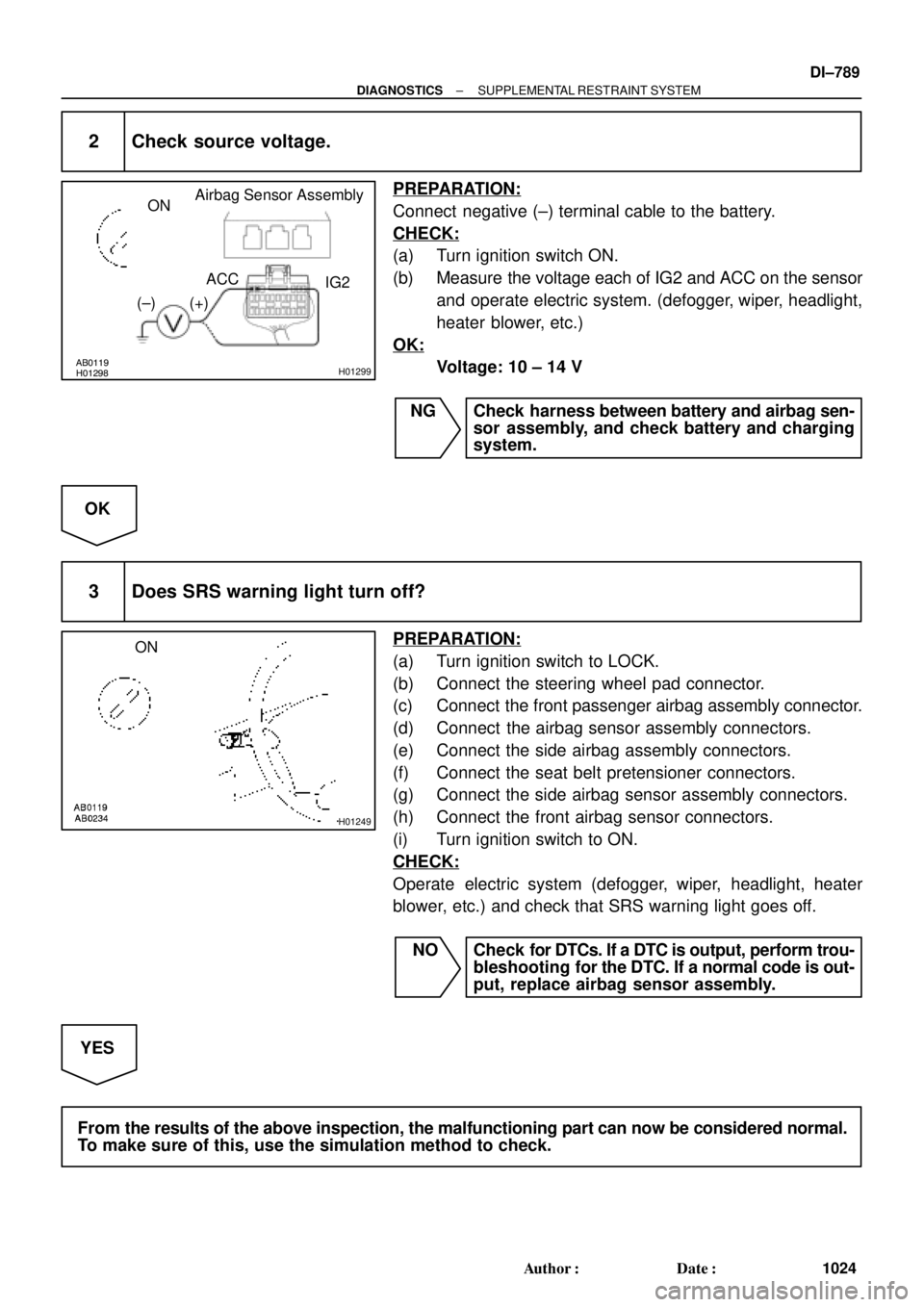
2 Check source voltage.
PREPARATION:
Connect negative (±) terminal cable to the battery.
CHECK:
(a) Turn ignition switch ON.
(b) Measure the voltage each of IG2 and ACC on the sensor
and operate electric system. (defogger, wiper, headlight,
heater blower, etc.)
OK:
Voltage: 10 ± 14 V
NG Check harness between battery and airbag sen-
sor assembly, and check battery and charging
system.
OK
3 Does SRS warning light turn off?
PREPARATION:
(a) Turn ignition switch to LOCK.
(b) Connect the steering wheel pad connector.
(c) Connect the front passenger airbag assembly connector.
(d) Connect the airbag sensor assembly connectors.
(e) Connect the side airbag assembly connectors.
(f) Connect the seat belt pretensioner connectors.
(g) Connect the side airbag sensor assembly connectors.
(h) Connect the front airbag sensor connectors.
(i) Turn ignition switch to ON.
CHECK:
Operate electric system (defogger, wiper, headlight, heater
blower, etc.) and check that SRS warning light goes off.
NO Check for DTCs. If a DTC is output, perform trou-
bleshooting for the DTC. If a normal code is out-
put, replace airbag sensor assembly.
YES
From the results of the above inspection, the malfunctioning part can now be considered normal.
To make sure of this, use the simulation method to check.
Page 3697 of 4770

B02389
B02390
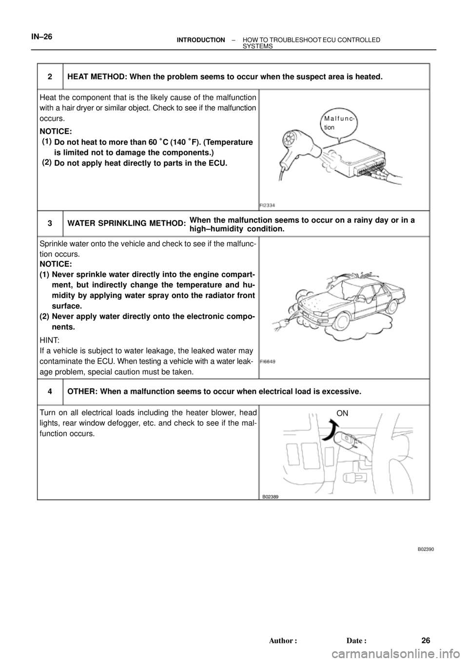
HEAT METHOD: When the problem seems to occur when the suspect area is heated. 2
NOTICE:3 WATER SPRINKLING METHOD:
(1)
(2)
4 OTHER: When a malfunction seems to occur when electrical load is excessive.When the malfunction seems to occur on a rainy day or in a
high±humidity condition. Heat the component that is the likely cause of the malfunction
with a hair dryer or similar object. Check to see if the malfunction
occurs.
Sprinkle water onto the vehicle and check to see if the malfunc-
tion occurs.
Turn on all electrical loads including the heater blower, head
lights, rear window defogger, etc. and check to see if the mal-
function occurs.ON HINT:
If a vehicle is subject to water leakage, the leaked water may
contaminate the ECU. When testing a vehicle with a water leak-
age problem, special caution must be taken.
Malfunc-
tion
Do not heat to more than 60 °C (140 °F). (Temperature
is limited not to damage the components.)
Do not apply heat directly to parts in the ECU. (1)
(2)
Never sprinkle water directly into the engine compart-
ment, but indirectly change the temperature and hu-
midity by applying water spray onto the radiator front
surface.
Never apply water directly onto the electronic compo-
nents. NOTICE: IN±26
± INTRODUCTIONHOW TO TROUBLESHOOT ECU CONTROLLED
SYSTEMS
26 Author�: Date�: