2000 TOYOTA CAMRY fog light
[x] Cancel search: fog lightPage 849 of 4770

'99camry U
83
To turn on the windshield wipers, move
the lever to the desired setting.
The key must be in the ºONº position.
Lever position
Speed setting
Position 1Intermittent
Position 2Slow
Position 3Fast
With interval adjuster: The ºINT TIMEº
band lets you adjust the wiping time inter-
val when the wiper lever is in the intermit-
tent position (position 1). Twist the band
upward to increase the time between
sweeps, and downward to decrease it.To squirt washer fluid, pull the lever
toward you.
If the windshield wipers are off, they will
operate a couple of times after the washer
squirts.
For instructions on adding washer fluid,
see ºAdding washer fluidº in Chapter 7±3.
In freezing weather, warm the windshield
with the defroster before using the washer.
This will help prevent the washer fluid
from freezing on your windshield, which
can block your vision.
NOTICE
Do not operate the wipers if the wind-
shield is dry. It may scratch the
glass.
To defog or defrost the rear window,
push the switch.
The key must be in the ºONº position.
The thin heater wires on the inside of the
rear window will quickly clear the sur-
faces. An indicator light will illuminate to
indicate the defogger is operating.
On some models, heater panels in the
outside rear view mirrors will also quickly
clear the surfaces.
Push the switch once again to turn the
defogger off.
The system will automatically shut off af-
ter the defogger has operated about 15
minutes.
Windshield wipers and
washerRear window and outside
rear view mirror defoggers
Page 1011 of 4770

'99camry U
245
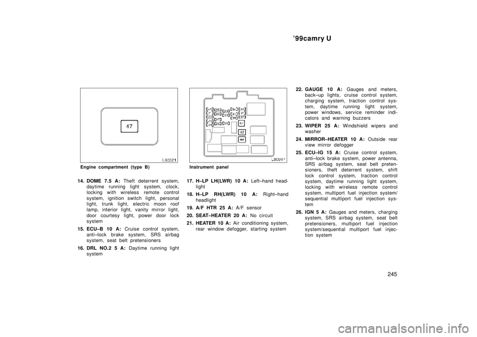
Engine compartment (type B)
14. DOME 7.5 A: Theft deterrent system,
daytime running light system, clock,
locking with wireless remote control
system, ignition switch light, personal
light, trunk light, electric moon roof
lamp, interior light, vanity mirror light,
door courtesy light, power door lock
system
15. ECU±B 10 A: Cruise control system,
anti±lock brake system, SRS airbag
system, seat belt pretensioners
16. DRL NO.2 5 A: Daytime running light
system
Instrument panel
17. H±LP LH(LWR) 10 A: Left±hand head-
light
18. H±LP RH(LWR) 10 A: Right±hand
headlight
19. A/F HTR 25 A: A/F sensor
20. SEAT±HEATER 20 A: No circuit
21. HEATER 10 A: Air conditioning system,
rear window defogger, starting system22. GAUGE 10 A: Gauges and meters,
back±up lights, cruise control system,
charging system, traction control sys-
tem, daytime running light system,
power windows, service reminder indi-
cators and warning buzzers
23. WIPER 25 A: Windshield wipers and
washer
24. MIRROR±HEATER 10 A: Outside rear
view mirror defogger
25. ECU±IG 15 A: Cruise control system,
anti±lock brake system, power antenna,
SRS airbag system, seat belt preten-
sioners, theft deterrent system, shift
lock control system, traction control
system, daytime running light system,
locking with wireless remote control
system, multiport fuel injection system/
sequential multiport fuel injection sys-
tem
26. IGN 5 A: Gauges and meters, charging
system, SRS airbag system, seat belt
pretensioners, multiport fuel injection
system/sequential multiport fuel injec-
tion system
Page 1012 of 4770

'99camry U
246
27. STOP 15 A: Stop lights, cruise control
system, high±mounted stoplight, anti±
lock brake system, shift lock control
system, multiport fuel injection system/
sequential multiport fuel injection sys-
tem
28. TAIL 10 A: Parking lights, license plate
lights, tail lights, front side marker
lights, daytime running light system,
multiport fuel injection system/sequen-
tial multiport fuel injection system
29. POWER±OUTLET 15 A: Power outlet
30. OBD 7.5 A: On±board diagnosis sys-
tem
31. FOG 15 A: No circuit
32. STARTER 5 A: Gauges and meters,
Multiport fuel injection system/sequen-
tial multiport fuel injection system
33. DOOR 25 A: Power door lock system,
theft deterrent system, fuel filler door
control system34. PANEL 7.5 A: Gauge and meter, audio
system, cigarette lighter, glove box
light, clock, instrument panel light con-
trol, service reminder indicators, air
conditioning control panel lights, ash-
tray light, emergency flasher, seat heat-
er control system, daytime running light
system, rear window defogger, electron-
ically controlled automatic transmission
system
35. TURN 7.5 A: Emergency flasher
36. RAD±NO.2 7.5 A: Audio system, power
antenna
37. CIG 15 A: Cigarette lighter, shift lock
control system, power rear view mirror
controls, theft deterrent system, power
door lock system, SRS airbag system,
seat belt pretensioners, outside rear
view mirror defogger, air conditioning
system
Fuses (type B)
38. CDS 30 A: Electric cooling fans
39. RDI 30 A: Electric cooling fans
40. MAIN 40 A: ºHEAD RH(UPR)º, ºHEAD
RHº, ºH±LP RH(LWR)º fuses
41. HTR 50 A: ºAM1º, ºA/Cº fuses
42. DEF 40 A: Rear window defogger43. PWR 30 A: Power window control sys-
tem, power seat, electric moon roof
44. AM1 40 A: Head lamp cleaner
45. T±STK 40 A or CDS NO.2 30 A: No
Circuit
Fuses (type C)
46. ALT 100 A: ºRDIº, ºCDSº fuses
47. ABS 60 A: Anti±lock brake system
Page 1083 of 4770

NEW FEATURES Ð 5S-FNE ENGINE
(Continued)
PIM
NE
G
THW
THA
VTA
AF
#10+
#20
#30
#40
IGT1,
IGT2
IGF
RSD
EGR
OX2
HTAF
HT2
MGC
FUEL W
PSW
ELS
NSW
F/PS
A/C SW
ECM
STA
SPD
R,2,L
STP
#40+ #30+ #20+ #10
FUEL
20
2. Construction
The configuration of the engine control system in the 5S-FNE engine is as shown in the following chart.
SENSORS
MANIFOLD ABSOLUTE
PRESSURE SENSOR
CRANKSHAFT POSITION
SENSOR
CAMSHAFT POSITION
SENSOR
ENGINE COOLANT TEMP.
SENSOR
INTAKE AIR TEMP. SENSOR
THROTTLE POSITION SENSOR
IGNITION SWITCH
COMBINATION METER
wVehicle Speed Signal
AIR FUEL RATIO SENSOR
(Bank 1, Sensor 1)
HEATED OXYGEN SENSOR
(Bank 1, Sensor 2)
POWER STEERING OIL
PRESSER SWITCH
TAILLIGHT & REAR WINDOW
DEFOGGER SYSTEM
PARK/NEUTRAL POSITION
SWITCH
STOP LIGHT SWITCH
AIR CONDITIONING SWITCH
AIRBAG SENSOR ASSEMBLY
wFuel Cut-Off Signal
ACTUATORS
SFI
No. 1 INJECTOR
No. 2 INJECTOR
No. 3 INJECTOR
No. 4 INJECTOR
ESA
IGNITERS and
IGNITION COILS
SPARK PLUGS
IAC
CONTROL VALVE
EGR
VSV
AIR FUEL RATIO SENSOR
HEATER CONTROL
AIR FUEL RATIO SENSOR
HEATER
OXYGEN SENSOR HEATER
CONTROL
HEATED OXYGEN SENSOR
HEATER
AIRE CONDITIONING
CUT-OFF CONTROL
MAGNET CLUTCH RERAY
FUEL GAGE
LOW FUEL LEVEL WARNING
LIGHT
Page 1099 of 4770

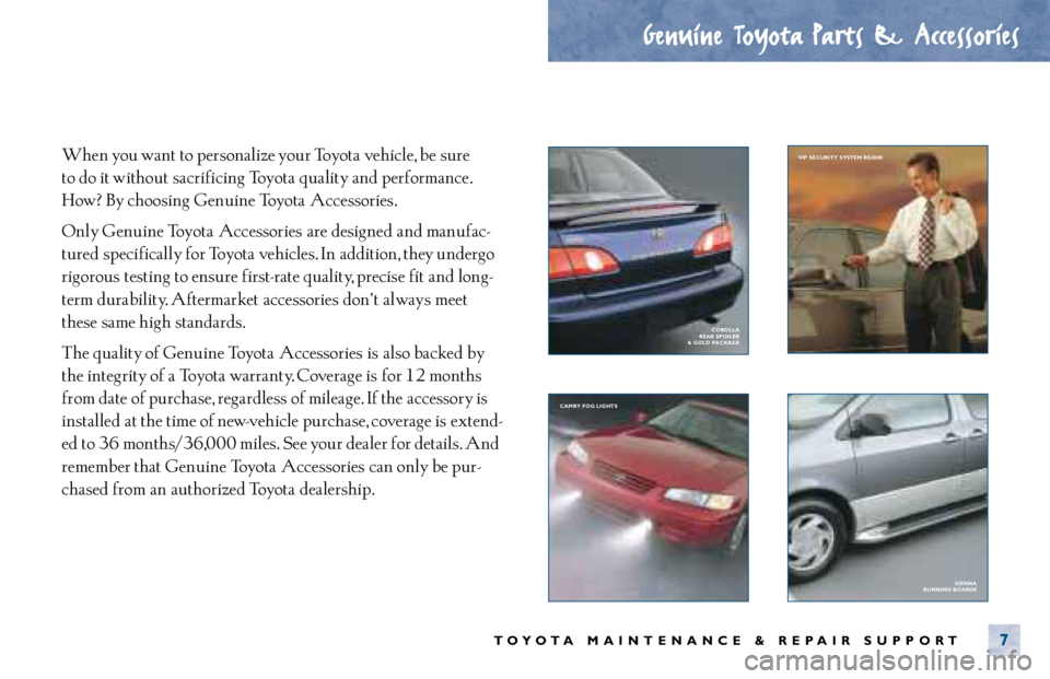
When you want to personalize your Toyota vehicle, be sure
to do it without sacrificing Toyota quality and performance.
How? By choosing Genuine Toyota Accessories.
Only Genuine Toyota Accessories are designed and manufac-
tured specifically for Toyota vehicles. In addition, they undergo
rigorous testing to ensure first- rate quality, precise fit and long-
term durability. Aftermarket accessories don’ t always meet
these same high standards.
The quality of Genuine Toyota Accessories is also backed by
the integrity of a Toyota warranty. Coverage is for 12 months
from date of purchase, regardless of mileage. If the accessory is
installed at the time of new- vehicle purchase, coverage is extend-
ed to 36 months/36,000 miles. See your dealer for details. And
remember that Genuine Toyota Accessories can only be pur-
chased from an authorized Toyota dealership.
Genuine Toyota Parts & Accessories
TOYOTA MAINTENANCE & REPAIR SUPPORT7
SIENNA
RUNNING BOARDS CAMRY FOG LIGHTS VIP SECURITY SYSTEM RS3000
COROLLA
REAR SPOILER
& GOLD PACKAGE
Page 1157 of 4770

B HOW TO USE THIS MANUAL
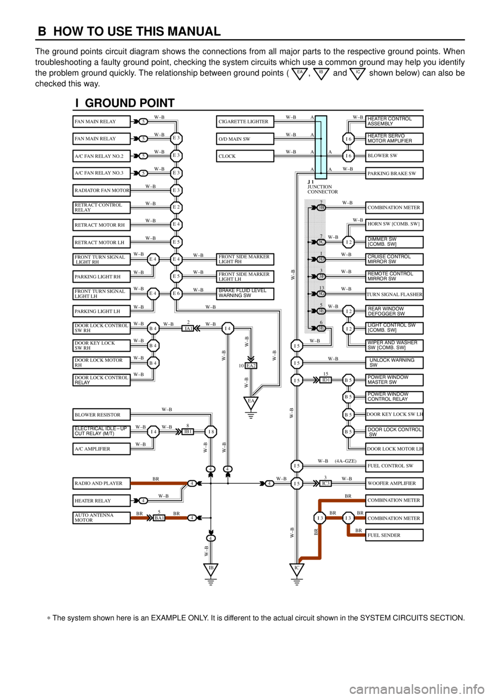
The ground points circuit diagram shows the connections from all major parts to the respective ground points. When
troubleshooting a faulty ground point, checking the system circuits which use a common ground may help you identify
the problem ground quickly. The relationship between ground points (
EA, IB and IC shown below) can also be
checked this way.
���� ���� ���� ���� ���� ���� ���� ���� ���� ���� ���� ���� ���� ���� ���� ���� ���� ���� ����
I GROUND POINT
FAN MAIN RELAY
FAN MAIN RELAY
A/C FAN RELAY NO.2
A/C FAN RELAY NO.3
RADIATOR FAN MOTOR
RETRACT CONTROL
RELAY
RETRACT MOTOR RH
RETRACT MOTOR LH
FRONT TURN SIGNAL
LIGHT RH
PARKING LIGHT RH
FRONT TURN SIGNAL
LIGHT LH
PARKING LIGHT LH
DOOR LOCK CONTROL
SW RH
DOOR KEY LOCK
SW RH
DOOR LOCK MOTOR
RH
BLOWER RESISTOR
A/C AMPLIFIER
RADIO AND PLAYER
HEATER RELAY
AUTO ANTENNA
MOTOR
BLOWER SW
PARKING BRAKE SW
COMBINATION METER
HORN SW [COMB. SW]
TURN SIGNAL FLASHER
DOOR KEY LOCK SW LH
DOOR LOCK MOTOR LH
FUEL CONTROL SW
WOOFER AMPLIFIER
COMBINATION METER
COMBINATION METER
FUEL SENDER
CIGARETTE LIGHTER
O/D MAIN SW
CLOCK
5
5
5
5
4
4
4
4
4BA15
IB18
EA2 10
3E5
3E
6 3G
13 3F
3 3D
1 3B
7
ID115
IC33
IA12
E 3
A
A AW±B
W±BW±B W±B
W±B W±B
W±B
W±B
W±B
W±B
W±B
W±B
W±B
W±B
W±B W±BW±B W±B W±B W±B
W±B W±B
W±BW±B
W±B
W±B
W±B W±B
W±B
BR
W±B
BR BRW±BW±B
W±B
W±B
W±B
W±B
W±B
W±B
W±B
W±B
W±B W±B
W±B
W±B
W±B
W±B
BR W±B
BR BR
BR W±B W±BW±B
W±BW±BBR W±B (4A±GZE)
W±B A A A
I 6
I 6
I 2
I 2
I 2
B 5I 5
I 5
I 5
B 5
B 5
B 5
I 5
I 5
I 3I 3
E 3
E 3
E 3
E 2
E 4
E 5
E 4
E 5
E 6E 4
E 4
B 4
EAI 4
B 4
B 4
I 4I 8
IBIC
3C7
4
JUNCTION
CONNECTOR J 1
4
DOOR LOCK CONTROL
RELAY
ELECTRICAL IDLE-UP
CUT RELAY (M/T)FRONT SIDE MARKER
LIGHT RH
FRONT SIDE MARKER
LIGHT LH
BRAKE FLUID LEVEL
WARNING SW
UNLOCK WARNING
SW WIPER AND WASHER
SW [COMB. SW] LIGHT CONTROL SW
[COMB. SW] HEATER CONTROL
ASSEMBLY
HEATER SERVO
MOTOR AMPLIFIER
DIMMER SW
[COMB. SW]
CRUISE CONTROL
MIRROR SW
REAR WINDOW
DEFOGGER SW
POWER WINDOW
MASTER SW
POWER WINDOW
CONTROL RELAY
DOOR LOCK CONTROL
SW
REMOTE CONTROL
MIRROR SW
* The system shown here is an EXAMPLE ONLY. It is different to the actual circuit shown in the SYSTEM CIRCUITS SECTION.
Page 1158 of 4770

B
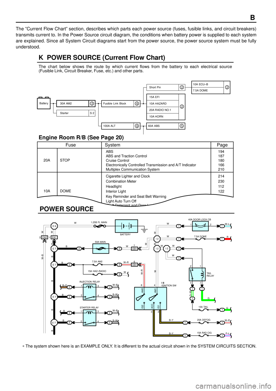
The ºCurrent Flow Chartº section, describes which parts each power source (fuses, fusible links, and circuit breakers)
transmits current to. In the Power Source circuit diagram, the conditions when battery power is supplied to each system
are explained. Since all System Circuit diagrams start from the power source, the power source system must be fully
understood.
Theft Deterrent and Door Lock Control
K POWER SOURCE (Current Flow Chart)
11
1
EA1 1EA2 3
7
EB16
E 6
E 7I 2I 2
I 2
E 7
E 7
E 7
2
1
1
2
2
2
2
2
B
B
W W
B B B B BW±B
B
B
B B±O
B±W
W±B
B±W STARTER RELAY INJECTION RELAY15A HAZ±RADIO7.5A AM250A MAIN 1.25B FL MAIN
BATTERY
WWW
W W W
R W±L
W
W
G±W
G
15A TAIL
20A DEFOG
15A RAD CIGTA I L
RELAY 7.5A DOME 40A DOOR LOCK CB
2 1
1 2
4 8
2 3
3 4
G
W±R
P±L B±Y
B±Y
W±R
AM2 IG2
ACC
IG1AM1W W
W±R
W W
W±B
21
1
1
1
1
2
2
2
2
3
4
3
4 1
2
1
22
1
11
1
IGNITION SW I 8
Battery
30A AM2
2
Starter S 220A RADIO NO.1
10A HORN
15A EFI
7.5A DOMEShort Pin
10A HAZARD
The chart below shows the route by which current flows from the battery to each electrical source
(Fusible Link, Circuit Breaker, Fuse, etc.) and other parts.
Engine Room R/B (See Page 20)
ABS
ABS and Traction Control
Cruise Control
Electronically Controlled Transmission and A/T Indicator
Multiplex Communication System
Cigarette Lighter and Clock
Key Reminder and Seat Belt Warning STOP
Fuse Page
194
214
11 2
System
DOME 20A
10ACombination Meter
Headlight
Interior Light
2
2
6 100A ALT
EB1
POWER SOURCE
Light Auto Turn Off187
180
166
210
230
122
10A ECU±B
5 60A ABS
2
6 Fusible Link Block2
* The system shown here is an EXAMPLE ONLY. It is different to the actual circuit shown in the SYSTEM CIRCUITS SECTION.
Page 1180 of 4770

G
Position of Parts in Instrument Panel
J 1 Junction Connector
J 2 Junction Connector
J 3 Junction Connector
J 4 Junction Connector
J 5 Junction Connector
J 6 Junction Connector
J 7 Junction Connector
J 8 Junction Connector
J 9 Junction Connector
J 10 Junction Connector
J 11 Junction Connector
J 12 Junction Connector
J 13 Junction Connector
J 14 Junction Connector
J 15 Junction Connector
J 16 Junction Connector
J 17 Junction Connector
J 18 Junction Connector
J 19 Junction Connector
J 20 Junction Connector
J 21 Junction Connector
J 22 Junction Connector
J 23 Junction Connector
J 24 Junction Connector
J 25 Junction Connector
J 26 Junction Connector
J 27 Junction Connector
J 28 Junction Connector
J 29 Junction Connector
J 30 Junction Connector
J 31 Junction Connector
J 32 Junction Connector
J 33 Junction ConnectorJ 34 Junction Connector
J 35 Junction Connector
J 36 Junction Connector
J 37 Junction Connector
K 3 Key Interlock Solenoid
O 2 O/D Main SW and A/T Shift Lever Illumination
P 3 Parking Brake SW
P 4 Power Outlet
R 2 Radio and Player
R 3 Radio and Player
R 4 Radio and Player
R 5 Rear Window Defogger SW
R 6 Remote Control Mirror SW
R 7 Rheostat
S 3 Shift Lock ECU
S 4 Stereo Component Amplifier
S 5 Stereo Component Amplifier
S 6 Stop Light SW
T 3 Theft Deterrent ECU
T 4 Theft Deterrent ECU
T 5 Traction Off SW
T 6 Turn Signal Flasher
T 7 Transponder Key Amplifier
U 1 Unlock Warning SW
W 6 Wireless Door Lock ECU