Page 3766 of 4770
MANUAL TRANSAXLE UNIT
MX±7
1857 Author�: Date�:
23. REMOVE FRONT SUSPENSION MEMBER WITH LOW-
ER SUSPENSION ARM
(a) Remove the LH and RH f")
Q10008
C
C
A
CBA
ABC A
Q10011
Q10009
± MANUAL TRANSAXLE (S51)MANUAL TRANSAXLE UNIT
MX±7
1857 Author�: Date�:
23. REMOVE FRONT SUSPENSION MEMBER WITH LOW-
ER SUSPENSION ARM
(a) Remove the LH and RH fender liner set screws.
(b) Remove the 6 bolts, 4 nuts, front LH and RH suspension
member braces, rear LH and RH suspension member
braces and front suspension member with the lower sus-
pension arm.
Torque:
Bolt A: 181 N´m (1,850 kgf´cm, 134 ft´lbf)
Bolt B: 32 N´m (330 kgf´cm, 24 ft´lbf)
Nut C: 36 N´m (370 kgf´cm, 27 ft´lbf)
24. JACK UP TRANSAXLE SLIGHTLY
Using a transmission jack, support the transaxle.
25. REMOVE LH STIFFENER PLATE
Remove the 3 bolts and LH stiffener plate.
Torque: 37 N´m (380 kgf´cm, 27 ft´lbf)
26. REMOVE REAR END PLATE WITH OIL PAN INSULA-
TOR AND RH STIFFENER PLATE
(a) Remove the 2 bolts and rear end plate with the oil pan in-
sulator.
Torque: 9.3 N´m (95 kgf´cm, 82 in.´lbf)
(b) Remove the 2 bolts and manifold stay.
Torque: 39 N´m (400 kgf´cm, 29 ft´lbf)
(c) Remove the 4 bolts and RH stiffener plate.
Torque: 39 N´m (400 kgf´cm, 29 ft´lbf)
27. REMOVE TRANSAXLE
Lower the engine left side and remove the transaxle from the
engine.
HINT:
At the time of installation, please refer to the following items.
�Align the input shaft with the clutch disc and install the
transaxle to the engine.
�Temporarily tighten the transaxle mounting bolts.
Page 3768 of 4770

MX04F±02
Z19123
Transmission Case Cover5th Driven GearRear Bearing Retainer
No.3 Shift Fork N0.3 Hub Sleeve No.3 Clutch Hub Assembly Needle Roller BearingRelease ForkTransmission
CaseDifferential Side
Bearing Retainer
Transmission
Case Protector Straight Screw Plug
Shift and Select Lever
Assembly
Selecting Bellcrank Back±UP
Light SwitchLock Ball
Assembly Release Bearing
Retainer
Vehicle
Speed Sensor
Release
BearingReverse
Restrict Pin�
O±Ring �Shim
x 6 Slotted
Spring Pin
Gasket
Clutch Release Fork
Support
x 17
Snap RingLock Nut Filler Plug
Lock Boltx 5
Spacer
5th Gear
x 8 Boot
�
Gasket �
Gasket �Drain Plug
Snap Ring�
�
�
� �Non±reusable part
Precoated part: Specified torque
N´m (kgf´cm, ft´lbf)
5.4 (55, 48 in.´lbf)
13 (130, 9)
123 (1,250, 90)�
37 (375, 27)29 (300, 22)�
44 (450, 33)
18 (185, 13)
18 (185, 13)
42 (430, 31)
29 (300, 22)
29 (300, 22)
49 (500, 36)
39 (400, 29)
18 (185, 13)
29 (300, 22)
7.4 (75, 65 in.´lbf)
37 (380, 27)
± MANUAL TRANSAXLE (S51)MANUAL TRANSAXLE ASSEMBLY
MX±9
1859 Author�: Date�:
MANUAL TRANSAXLE ASSEMBLY
COMPONENTS
Page 3770 of 4770
MANUAL TRANSAXLE ASSEMBLY
MX±11
1861 Author�: Date�:
DISASSEMBLY
1. REMOVE RELEASE FORK AND BEARING
2. REMOVE BACK±UP LIGHT SWITCH
Torque: 44 N´m (450")
MX04G±02
Z18142FIPG
± MANUAL TRANSAXLE (S51)MANUAL TRANSAXLE ASSEMBLY
MX±11
1861 Author�: Date�:
DISASSEMBLY
1. REMOVE RELEASE FORK AND BEARING
2. REMOVE BACK±UP LIGHT SWITCH
Torque: 44 N´m (450 kgf´cm, 33 ft´lbf)
3. REMOVE BOLT AND VEHICLE SPEED SENSOR
Torque: 5.4 N´m (55 kgf´cm, 48 in.´lbf)
4. REMOVE RELEASE BEARING RETAINER
Remove the 3 bolts and retainer.
Torque: 7.4 N´m (75 kgf´cm, 65 in.´lbf)
5. REMOVE SELECTING BELLCRANK
Remove the 2 bolts and selecting bellcrank.
Torque: 37 N´m (380 kgf´cm, 27 ft´lbf)
6. REMOVE TRANSMISSION CASE COVER
(a) Remove the 8 bolts.
Sealant:
Part No.08833 ± 00080, THREE BOND 1344, LOCTITE
242 or equivalent
Torque: 29 N´m (300 kgf´cm, 22 ft´lbf)
(b) Using a plastic hammer, tap the transmission case cover
and remove it.
FIPG:
Part No. 08826 ± 00090, THREE BOND 1281 or equiva-
lent
7. REMOVE LOCK BALL ASSEMBLY
Sealant:
Part No.08833 ± 00080, THREE BOND 1344, LOCTITE
242 or equivalent
Torque: 29 N´m (300 kgf´cm, 22 ft´lbf)
8. REMOVE SHIFT AND SELECT LEVER ASSEMBLY
HINT:
At the time of installation, please refer to the following item.
Apply FIPG to the underside of the flanged portion of the control
shaft cover.
FIPG:
Part No. 08826 ± 00090, THREE BOND 1281 or equiva-
lent
Torque: 37 N´m (375 kgf´cm, 27 ft´lbf)
Page 3773 of 4770
MANUAL TRANSAXLE ASSEMBLY
1864 Author�: Date�:
HINT:
At the time of installation, please refer to the following item.")
Q02682
SST
Q05785
x 5
Q05826
x 17
x 6
Q09474FIPG MX±14
± MANUAL TRANSAXLE (S51)MANUAL TRANSAXLE ASSEMBLY
1864 Author�: Date�:
HINT:
At the time of installation, please refer to the following item.
Using SST and a press, install the No.3 clutch hub assembly.
SST 09612±22011
(c) Remove the 5th gear.
15. REMOVE NEEDLE ROLLER BEARING
16. REMOVE REAR BEARING RETAINER
Remove the 5 bolts and retainer.
Sealant:
Part No.08833 ± 00070, THREE BOND 1324 or equiva-
lent
Torque: 42 N´m (430 kgf´cm, 31 ft´lbf)
17. REMOVE BEARING SNAP RING
Using a snap ring expander, remove the 2 snap rings.
HINT:
If it is difficult to remove and install the snap rings, pull up the
shafts.
18. REMOVE REVERSE IDLER GEAR SHAFT LOCK BOLT
AND GASKET
Torque: 29 N´m (300 kgf´cm, 22 ft´lbf)
19. REMOVE DIFFERENTIAL SIDE BEARING RETAINER
AND SHIM
Remove the 6 bolts, retainer and shim.
Sealant:
Part No.08833 ± 00080, THREE BOND 1344, LOCTITE
242 or equivalent
Torque: 18 N´m (185 kgf´cm, 13 ft´lbf)
20. REMOVE TRANSMISSION CASE
(a) Remove the 17 bolts.
Torque: 29 N´m (300 kgf´cm, 22 ft´lbf)
(b) Using a plastic hammer, tap the transmission case and re-
move it.
FIPG:
Part No. 08833 ± 00090, THREE BOND 1281 or equiva-
lent
Page 3792 of 4770
MX04Q±01
Q02949
Front
SM0199
SST
Z00428
Z00429
± MANUAL TRANSAXLE (S51)OUTPUT SHAFT
MX±33
1883 Author�: Date�:
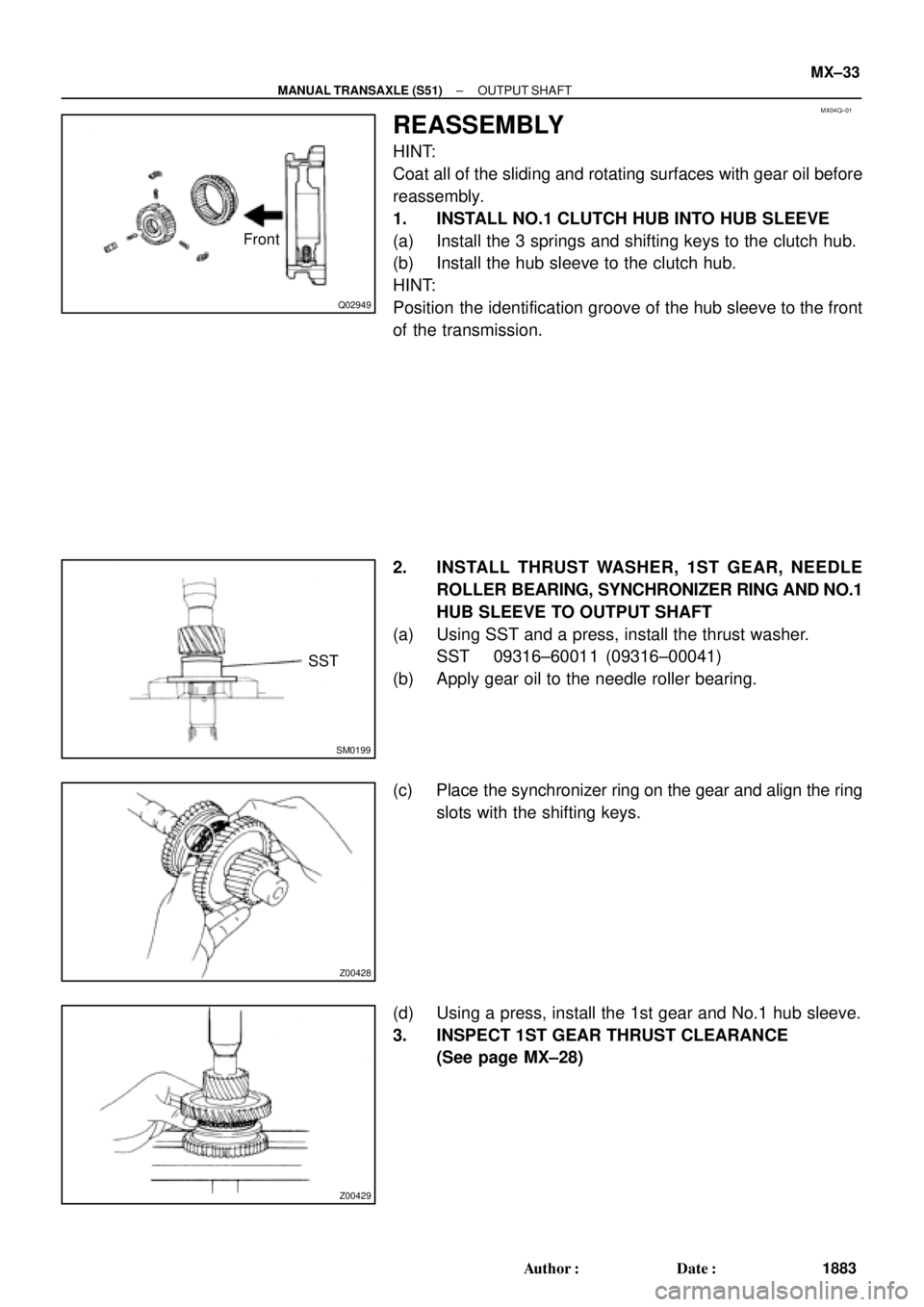
REASSEMBLY
HINT:
Coat all of the sliding and rotating surfaces with gear oil before
reassembly.
1. INSTALL NO.1 CLUTCH HUB INTO HUB SLEEVE
(a) Install the 3 springs and shifting keys to the clutch hub.
(b) Install the hub sleeve to the clutch hub.
HINT:
Position the identification groove of the hub sleeve to the front
of the transmission.
2. INSTALL THRUST WASHER, 1ST GEAR, NEEDLE
ROLLER BEARING, SYNCHRONIZER RING AND NO.1
HUB SLEEVE TO OUTPUT SHAFT
(a) Using SST and a press, install the thrust washer.
SST 09316±60011 (09316±00041)
(b) Apply gear oil to the needle roller bearing.
(c) Place the synchronizer ring on the gear and align the ring
slots with the shifting keys.
(d) Using a press, install the 1st gear and No.1 hub sleeve.
3. INSPECT 1ST GEAR THRUST CLEARANCE
(See page MX±28)
Page 3797 of 4770
DIFFERENTIAL CASE
1888 Author�: Date�:
6. Transaxle Case Side:
IF NECESSARY, REPLACE DIFFERENTIAL SIDE
BEARING RETAIN")
Q08145
SST
SM0286
SST
SM0155
SST
Z00442
MT0634
SST MX±38
± MANUAL TRANSAXLE (S51)DIFFERENTIAL CASE
1888 Author�: Date�:
6. Transaxle Case Side:
IF NECESSARY, REPLACE DIFFERENTIAL SIDE
BEARING RETAINER OIL SEAL
(a) Using SST and a hammer, drive out the oil seal from the
retainer.
SST 09950±60020 (09951±00680), 09950±70010
(09951±07150)
(b) Using SST and a hammer, drive in a new oil seal until its
surface is flush with the case surface.
SST 09350±32014 (09351±32130, 09351±32150)
(c) Coat the lip of the oil seal with MP grease.
7. Transmission Case Side:
IF NECESSARY, REPLACE SIDE OIL SEAL
(a) Using a screwdriver and hammer, drive out the oil seal.
(b) Using SST and a hammer, drive in a new oil seal until its
surface is flush with the case surface.
SST 09350±32014 (09351±32130, 09351±32150)
(c) Coat the lip of the oil seal with MP grease.
8. Transaxle Case Side:
IF NECESSARY, REPLACE SIDE BEARING OUTER
RACE
(a) Using a brass bar and hammer, drive out the bearing out-
er race.
(b) Install the bearing retainer without an O±ring.
(c) Install and torque the 6 bolts.
Torque: 18 N´m (185 kgf´cm, 13 ft´lbf)
(d) Place the thinnest shim into the case.
(e) Using SST and a press, install a new bearing outer race.
SST 09950±60020 (09951±00680), 09950±70010
(09951±07150)
(f) Remove the 6 bolts.
(g) Remove the bearing retainer and shim.
Page 3800 of 4770
DIFFERENTIAL CASE
MX±41
1891 Author�: Date�:
3. INSTALL SIDE BEARING TO DIFFERENTIAL CASE
(a) Using SST and a press, install a new side")
SM0287
SST
Q08649
Case Side
SM0289
SST
± MANUAL TRANSAXLE (S51)DIFFERENTIAL CASE
MX±41
1891 Author�: Date�:
3. INSTALL SIDE BEARING TO DIFFERENTIAL CASE
(a) Using SST and a press, install a new side bearing to the
transmission case side.
SST 09316±60011 (09316±00011), 09350±32014
(09351±32120)
(b) Install the vehicle speed sensor drive gear to the trans-
axle case side.
(c) Using SST and a press, install a new side bearing to the
transaxle case side.
SST 09316±60011 (09316±00011), 09350±32014
(09351±32120)
NOTICE:
Install the black cage bearing on the vehicle speed sensor
drive gear side.
4. ADJUST DIFFERENTIAL CASE SIDE BEARING PRE-
LOAD
(a) Install the differential to the transaxle case.
(b) Install the transmission case.
(c) Install and torque the case bolts.
Torque: 29 N´m (300 kgf´cm, 22 ft´lbf)
(d) Install the shim into the transmission case.
(e) Install the bearing retainer without an O±ring.
(f) Install and torque the 6 bolts.
Torque: 18 N´m (185 kgf´cm, 13 ft´lbf)
Page 3801 of 4770
Z00620
SST MX±42
± MANUAL TRANSAXLE (S51)DIFFERENTIAL CASE
1892 Author�: Date�:
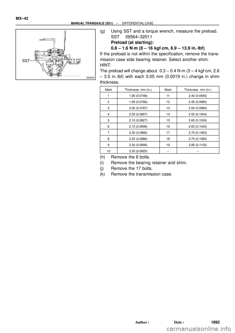
(g) Using SST and a torque wrench, measure the preload.
SST 09564±32011
Preload (at starting):
0.8 ± 1.6 N´m (8 ± 16 kgf´cm, 6.9 ± 13.9 in.´lbf)
If the preload is not within the specification, remove the trans-
mission case side bearing retainer. Select another shim.
HINT:
The preload will change about 0.3 ± 0.4 N´m (3 ± 4 kgf´cm, 2.6
± 3.5 in.´lbf) with each 0.05 mm (0.0019 in.) change in shim
thickness.
MarkThickness mm (in.)MarkThickness mm (in.)
11.90 (0.0748)112.40 (0.0945)
21.95 (0.0768)122.45 (0.0965)
32.00 (0.0787)132.50 (0.0984)
42.05 (0.0807)142.55 (0.1004)
52.10 (0.0827)152.60 (0.1024)
62.15 (0.0846)162.65 (0.1043)
72.20 (0.0866)172.70 (0.1063)
82.25 (0.0886)182.75 (0.1083)
92.30 (0.0906)192.80 (0.1102)
102.35 (0.0925)±±
(h) Remove the 6 bolts.
(i) Remove the bearing retainer and shim.
(j) Remove the 17 bolts.
(k) Remove the transmission case.