Page 287 of 4770
TORQUE SPECIFICATIONS
No.1 air intake chamber stay x Intake manifold
No.1 air intake chamber stay x Cylinder headFuel return pipe x Fuel pressure regulator Fuel pressure regulator x Delivery pipe
Fuel pulsation damper x Delivery pipe
Intake manifold stay x Intake manifold
Intake manifold stay x Cylinder blockFuel line (Flare nut type ± use SST)
Throttle body x Intake manifoldIntake manifold x Cylinder headDelivery pipe x Cylinder head
EGR pipe x Intake manifoldFuel pump side
Others Fuel line (Union bolt type)
Fuel pump x Fuel tankFuel tank band x Body
EGR pipe union nutPart tightened
± 5S±FE ENGINEMFI/SFI SYSTEMEG1±237
Page 353 of 4770
wOpen or short in injector circuit
wFuel line pressure (injector leak, blockage)
wMechanical system malfunction (skipping teeth of timing
belt)
wIgnition system
w Compression pressure (foreign object caught in valve)
wAir leakage
wECM wOpen or short in main oxygen sensor circuit
wMain oxygen sensor
wignition system
wECM wOpen or short in engine coolant temp. sensor circuit
wEngine coolant temp. sensor
wECM
wOpen or short in intake air temp. sensor circuit
wIntake air temp. sensor
wECM wMain oxygen sensor circuit
w Main oxygen sensorMalfunction
Indicator
Lamp*�
*�,*�: See page EG1±306Normal
Mode Trouble AreaMemory`
Test
ModeSee page
EG1±360
EG1±363EG1±352
EG1±356
± 5S±FE ENGINEDIAGNOSTIC TROUBLE CODE CHARTEG1±303
Page 355 of 4770
wOpen or short in injector circuit
wFuel line pressure (injector leak, blockage)
wMechanical system malfunction (skipping teeth of timing
belt)
wIgnition system
wCompression pressure (foreign object caught in valve)
wAir leakage
w ECM
wOpen or short in No.1 vehicle speed sensor circuit
wNo.1 vehicle speed sensor
wCombination meter
wECM wOpen or short in manifold absolute pressure sensor circuit.
wManifold absolute pressure sensor
wECM
wOpen or short in throttle position sensor circuit
wThrottle position sensor
wECM wOpen or short in sub oxygen sensor circuit
wSub oxygen sensor
wECMMalfunction
Indicator
Lamp*�
*�,*�: See page EG1±306Normal
Mode Trouble Area
Memory*�
Test
ModeSee page
EG1±380EG1±369
EG1±376EG1±372EG1±363
OFF OFF
± 5S±FE ENGINEDIAGNOSTIC TROUBLE CODE CHARTEG1±305
Page 413 of 4770

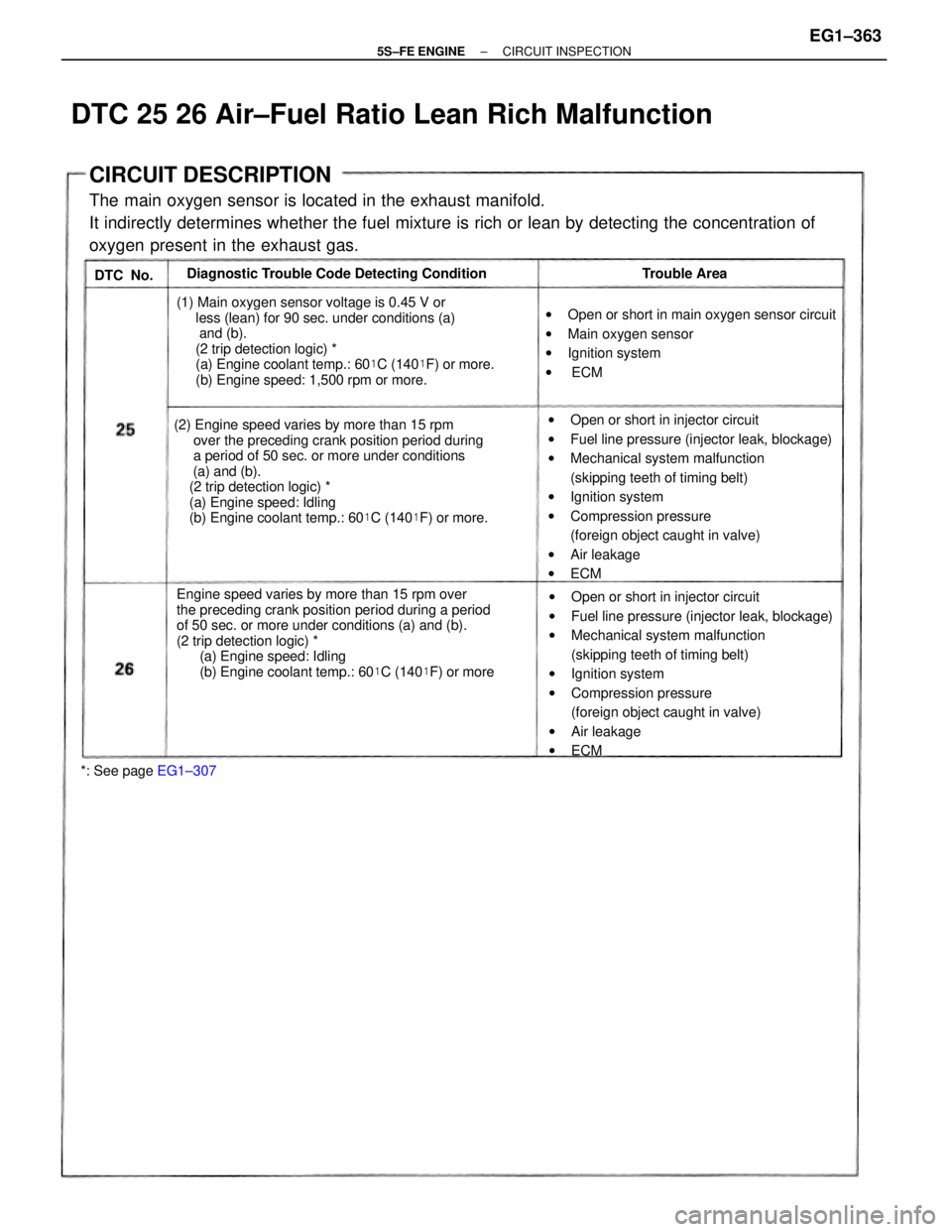
CIRCUIT DESCRIPTION
The main oxygen sensor is located in the exhaust manifold.
It indirectly determines whether the fuel mixture is rich or lean by detecting the concentration of
oxygen present in the exhaust gas.
Engine speed varies by more than 15 rpm over
the preceding crank position period during a period
of 50 sec. or more under conditions (a) and (b).
(2 trip detection logic) *
(a) Engine speed: Idling
(b) Engine coolant temp.: 60�C (140�F) or more (2) Engine speed varies by more than 15 rpm
over the preceding crank position period during
a period of 50 sec. or more under conditions
(a) and (b).
(2 trip detection logic) *
(a) Engine speed: Idling
(b) Engine coolant temp.: 60�C (140�F) or more.wOpen or short in injector circuit
wFuel line pressure (injector leak, blockage)
wMechanical system malfunction
(skipping teeth of timing belt)
wIgnition system
wCompression pressure
(foreign object caught in valve)
wAir leakage
wECM
wOpen or short in injector circuit
wFuel line pressure (injector leak, blockage)
wMechanical system malfunction
(skipping teeth of timing belt)
wIgnition system
wCompression pressure
(foreign object caught in valve)
wAir leakage
wECM (1) Main oxygen sensor voltage is 0.45 V or
less (lean) for 90 sec. under conditions (a)
and (b).
(2 trip detection logic) *
(a) Engine coolant temp.: 60�C (140�F) or more.
(b) Engine speed: 1,500 rpm or more.wOpen or short in main oxygen sensor circuit
wMain oxygen sensor
wIgnition system
w ECM Diagnostic Trouble Code Detecting Condition
*: See page EG1±307Trouble Area
DTC 25 26 Air±Fuel Ratio Lean Rich Malfunction
DTC No.
± 5S±FE ENGINECIRCUIT INSPECTIONEG1±363
Page 489 of 4770

8
MAJOR COMPONENTS
The basic components of the new and previous Camry are as follows:
Model
NEWPREVIOUSItemNEWPREVIOUS
Drive SystemFF (Front Engine Wheel Drive)u
Type5S±FE: In±Line 4, 2.2±Literu
Displacement cm3 (cu. in.)2164 (132.0)u
Valve Mechanism16 Valves, DOHCu
eFuel SystemSFIu
n±Line
Engine
Max. Output [SAE±NET]
kW @ rpm (HP @ rpm)99 @ 5200 (133 @ 5200)
97 @ 5200 (130 @ 5200)*93 @ 5400 (125 @ 5400)
In± 4
E
Max. Torque [SAE±NET]
N
.m @ rpm (ft.lbf @ rpm)
199 @ 4400 (147 @ 4400)
197 @ 4400 (145 @ 4400)*197 @ 4400 (145 @ 4400)
Type1MZ±FE: V6, 3.0±Literu
Displacement cm3 (cu. in.)2995 (182.7)u
Valve Mechanism24 Valves, DOHCu
Fuel SystemSFIu
Engine
Max. Output [SAE±NET]
kW @ rpm (HP @ rpm)145 @ 5200 (194 @ 5200)140 @ 5200 (188 @ 5200)
V6
E
Max. Torque [SAE±NET]
N
.m @ rpm (ft.lbf @ rpm)283 @ 4400 (209 @ 4400)275 @ 4400 (203 @ 4400)
ClutchDry Type Single Plateu
Transaxle
Manual S51: 5±Speed (For 5S±FE)
E153: 5±Speed (For 1MZ±FE) S51: 5±Speed (For 5S±FE)
AutomaticA140E: 4±Speed (For 5S±FE)
A541E: 4±Speed (For 1MZ±FE)u
FrontVentilated Discu
BrakesRearSXV20 Series : Leading Trailing Drum
MCV20 Series : Solid Disc
SXV10 Series without ABS:
Leading Trailing Drum
SXV10 Series with ABS
and MCV10 Series: Solid Disc
Suspension4±Wheel MacPherson Strutu
SteeringGear TypeRack and PinionuSteeringPower SteeringEngine Revolution Sensing Typeu
*: California Specification Model
Page 490 of 4770
![TOYOTA CAMRY 2000 Service Repair Manual 9
ENGINE
ENGINE LINE±UP
2 types of engine are available in the Camry, the 2.2±liter 5S±FE and the 3.0±liter 1MZ±FE engines.
Displace±
ment
Engine
TypeMax. Output
[SAE±NET]Max. Torque
[SAE±NET] TOYOTA CAMRY 2000 Service Repair Manual 9
ENGINE
ENGINE LINE±UP
2 types of engine are available in the Camry, the 2.2±liter 5S±FE and the 3.0±liter 1MZ±FE engines.
Displace±
ment
Engine
TypeMax. Output
[SAE±NET]Max. Torque
[SAE±NET]](/manual-img/14/57447/w960_57447-489.png)
9
ENGINE
ENGINE LINE±UP
2 types of engine are available in the Camry, the 2.2±liter 5S±FE and the 3.0±liter 1MZ±FE engines.
Displace±
ment
Engine
TypeMax. Output
[SAE±NET]Max. Torque
[SAE±NET]Features
2.2 liters5S±FE
99 kW @ 5200 rpm
(133 HP @ 5200 rpm)
97 kW @ 5200 rpm*
(130 HP @ 5200 rpm)*199 N.m @ 4400 rpm
(147 ft
.lbf @ 4400 rpm)
197 N
.m @ 4400 rpm*
(145 ft
.lbf @ 4400 rpm)*
The 5S±FE engine offers increased
torque in the low± to mid±speed
range and reduced exhaust
emissions.
3.0 liters1MZ±FE145 kW @ 5200 rpm
(194 HP @ 5200 rpm)283 N.m @ 4400 rpm
(209 ft
.lbf @ 4400 rpm)
The 1MZ±FE engine achieves
reduced exhaust emissions.
*: California Specification Models
� 5S±FE Engine
The 5S±FE engine is a 2.2±liter, 16±valve DOHC engine. Through the use of optimized intake and exhaust systems
and combustion chamber, this engine has improved its torque in the low± to mid±speed range. In addition, its
exhausts emissions have been reduced through the improvement of the engine control system.
� 1MZ±FE ENGINE
The 1MZ±FE engine is a V6, 3.0±liter, 24±valve DOHC engine. Through the adoption of the fuel returnless system
and the changes made to the EGR control system, the 1MZ±FE engine achieves a reduction of exhaust emissions.
Page 509 of 4770

30
ENGINE
5S±FE ENGINE
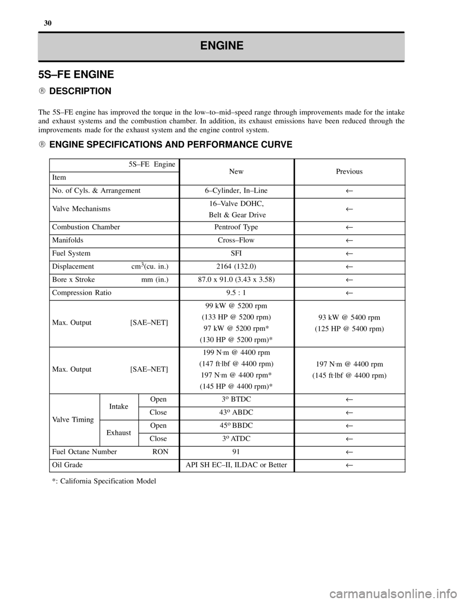
� DESCRIPTION
The 5S±FE engine has improved the torque in the low±to±mid±speed range through improvements made for the intake
and exhaust systems and the combustion chamber. In addition, its exhaust emissions have been reduced through the
improvements made for the exhaust system and the engine control system.
� ENGINE SPECIFICATIONS AND PERFORMANCE CURVE
5S±FE EngineNewPreviousItemNewPrevious
No. of Cyls. & Arrangement6±Cylinder, In±Lineu
Valve Mechanisms16±Valve DOHC,
Belt & Gear Driveu
Combustion ChamberPentroof Typeu
ManifoldsCross±Flowu
Fuel SystemSFIu
Displacement cm3(cu. in.)2164 (132.0)u
Bore x Stroke mm (in.)87.0 x 91.0 (3.43 x 3.58)u
Compression Ratio9.5 : 1u
Max. Output [SAE±NET]
99 kW @ 5200 rpm
(133 HP @ 5200 rpm)
97 kW @ 5200 rpm*
(130 HP @ 5200 rpm)*
93 kW @ 5400 rpm
(125 HP @ 5400 rpm)
Max. Output [SAE±NET]
199 N.m @ 4400 rpm
(147 ft
.lbf @ 4400 rpm)
197 N
.m @ 4400 rpm*
(145 HP @ 4400 rpm)*
197 N.m @ 4400 rpm
(145 ft
.lbf @ 4400 rpm)
IntakeOpen3o BTDCu
Valve Timing
IntakeClose43o ABDCuValve Timing
ExhaustOpen45o
BBDCuExhaustClose3o
ATDCu
Fuel Octane Number RON91u
Oil GradeAPI SH EC±II, ILDAC or Betteru
*: California Specification Model
Page 516 of 4770

37 ENGINEÐ5S±FE ENGINE
� ENGINE CONTROL SYSTEM
1. General
The engine control system of the new 5S±FE engine is basically the same in construction and operation as that of the
previous 5S±FE engine, except fo rthe changed listed bleow.
�The exhaust emissions has been reduced through the adoption of the sequential multiport fuel injection system for
engine starting and the air±fuel ratio sensor*
2
�The function of an air conditioning amplifier has been internally added to the ECM.
The engine control system of the new 5S±FE engine and previous 5S±FE engine and previous 5S±FE engine are
compared below.
System
OutlineNewPrevious
SFI
(SequentialA D±type SFI system is used, which indirectly detects
intake air volume by manifold absolute pressure.��(q
Multiport Fuel
Injection)The fuel injection system is a sequential multiport fuel
injection system.��
ESA
(Electronic SparkIgnition Timing is determined by the ECM based on
signals from various sensors. The ECM corrects ignition
timing in response to engine knocking.
��
(Electronic Spark
Advance)Torque control correction during gear shifting has been
used to minimize the shift shock.��*1��*1
IACA rotary solenoid type IAC valve controls the fast idle��(Idle Air Control)
A rotary solenoid type IAC valve controls the fast idle
and idle speeds.��
Fuel Pump
ControlFuel pump operation is controlled by signal from the
ECM.��
Oxygen Sensor
(Air Fuel Ratio
Sensor*
2)
Heater Control
Maintains the temperature of the oxygen sensor (or air
fuel ratio sensor*2) at an approppiate level to increase
accuracy of detection of the oxygen concentration in the
exhaust gas.�Ð
EGR Cut±Off
ControlCuts off EGR according to the engine condition to
maintain drivability of the vehicle and durability of
EGR components.
��
Evaporative
Emission ControlThe ECM controls the purge flow of evaporative emis-
sions (HC) in the charcoal canister in accordance with
engine conditions.
��*1��*1
Air Conditioning
Cut±Off ControlBy turning the air conditioning compressor ON or
OFF in accordance with the engine condition,
drivability is maintained
��*3�
Diagnosis
When the ECM detects a malfunction, the ECM diagnoses
and memorized the failed section.��
DiagnosisThe diagnosis system includes a function that detects a
malfunction in the evaporative control system.��*1��*1
Fail SafeWhen the ECM detects a malfunction, the ECM stops
or controls the engine according to the data already stored
in memory
��
*1: Only for Automatic Transaxle Models., *2: Only for California Specification Models,
*
3: The air conditioning magnet scutch controled by the ECM.