Page 225 of 4770
 Put a container under the connection.
(b) Slowly loos")
FUEL SYSTEM
1. When disconnecting the high pressure fuel line, a
large amount of gasoline will spill out, so observe the
following procedures:
(a) Put a container under the connection.
(b) Slowly loosen the connection.
(c) Disconnect the connection.
(d) Plug the connection with a rubber plug.
2. When connecting the flare nut or union bolt on the
high pressure pipe union, observe the following proce±
dures:
Union Bolt Type:
(a) Always use a new gasket.
(b) Tighten the union bolt by hand.
(c) Tighten the union bolt to the specified torque.
Torque: 29 N±m (300 kgf±cm, 22 ft±lbf)
Flare Nut Type:
(s) Apply alight coat of engine oil to the flare and tighten
the flare nut by hand.
(b) Using SST, torque the flare nut.
SST 09631±22020
Torque:
28 N±m (285 kgf±cm, 21 ft±lbf) for fuel pump side
30 N±m (310 kgf±cm, 22 ft±lbf) for others
HINT: Use a torque wrench with a fulcrum length of
30 cm (11.81 in.).
3. Observe the following precautions when removing
and installing the injectors.
(a) Never reuse the O±ring.
(b) When placing a new O±ring on the injector, take care
not to damage it in any way.
(c) Coat a new 0± ring with spindle oil or gasoline before
installing±never use engine, gear or brake oil.
4. Install the injector to delivery pipe and intake manifold
as shown in the illustration.
± 5S±FE ENGINEMFI/SFI SYSTEMEG1±175
Page 226 of 4770
5. Check that there are no fuel leaks after performing
maintenance anywhere on the fuel system.
(a) Using SST, connect terminals + B and FP of the data
link connector 1.
SST 09843±18020
(b) With engine stopped, turn the ignition switch ON.
(c) Pinch the fuel return hose. The pressure in high pres±
sure line will rise to approx. 392 kPa (4kgf/cm2, 57
psi). In this state, check to see that there are no leaks
from any part of the fuel system.
NOTICE: Always pinch the hose. Avoid bending as it may
cause the hose to crack.
(d) Turn the ignition switch OFF.
(9) Remove the SST.
SST 09843±18020
± 5S±FE ENGINEMFI/SFI SYSTEMEG1±176
Page 229 of 4770
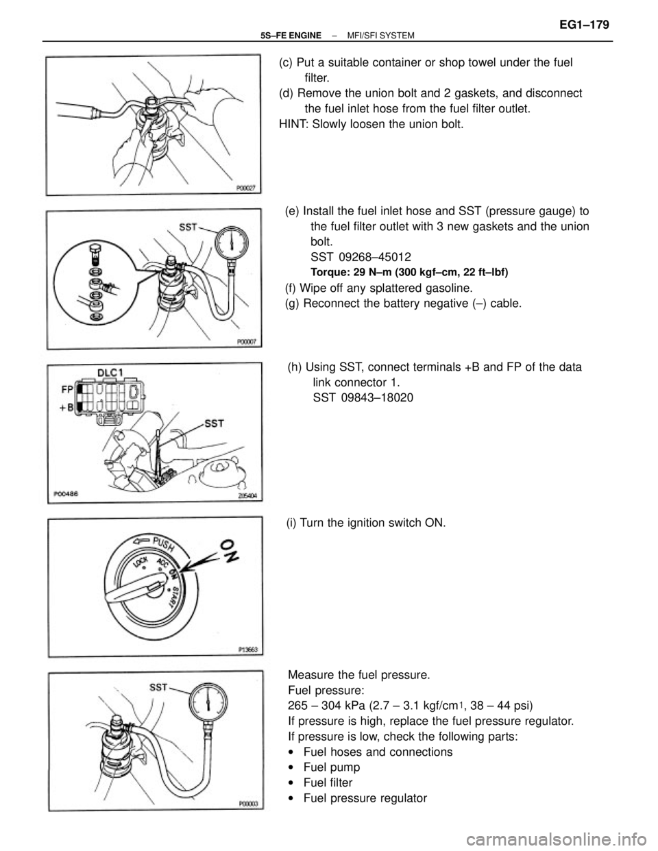
Measure the fuel pressure.
Fuel pressure:
265 ± 304 kPa (2.7 ± 3.1 kgf/cm�, 38 ± 44 psi)
If pressure is high, replace the fuel pressure regulator.
If pressure is low, check the following parts:
wFuel hoses and connections
wFuel pump
wFuel filter
wFuel pressure regulator (e) Install the fuel inlet hose and SST (pressure gauge) to
the fuel filter outlet with 3 new gaskets and the union
bolt.
SST 09268±45012
Torque: 29 N±m (300 kgf±cm, 22 ft±lbf)
(f) Wipe off any splattered gasoline.
(g) Reconnect the battery negative (±) cable. (c) Put a suitable container or shop towel under the fuel
filter.
(d) Remove the union bolt and 2 gaskets, and disconnect
the fuel inlet hose from the fuel filter outlet.
HINT: Slowly loosen the union bolt.
(h) Using SST, connect terminals +B and FP of the data
link connector 1.
SST 09843±18020
(i) Turn the ignition switch ON.
± 5S±FE ENGINEMFI/SFI SYSTEMEG1±179
Page 230 of 4770
 Stop the engine.
(r) Check that the fuel pressure remains 147 kPa (1.5
kgf/cm
2, 21 psi) or more for 5 minutes after the
engine is turned off.
If pressure is not as specified, check the fuel pump,")
(q) Stop the engine.
(r) Check that the fuel pressure remains 147 kPa (1.5
kgf/cm
2, 21 psi) or more for 5 minutes after the
engine is turned off.
If pressure is not as specified, check the fuel pump,
pressure regulator and/or injector.
(s) After checking fuel pressure, disconnect the battery
negative (±) cable and carefully remove the SST to
prevent gasoline from splashing.
SST 09268±45012
(t) Connect the fuel inlet hose with 2 new gaskets and
the union bolt.
Torque: 29 N±m (300 kgf±cm. 22 ft±lbf)
(u) Reconnect the cable to the negative (±) terminal of
the battery.
(v) Check for fuel leakage.(o) Reconnect the vacuum sensing hose to the air intake
chamber.
(p) Measure the fuel pressure at idle.
Fuel pressure:
206 ± 255 kPa (2.1 ± 2.6 kgf/cm�, 31 ± 37 psi)
If pressure is not as specified, check the vacuum
sensing hose and fuel pressure regulator.(l) Start the engine.
(m) Disconnect the vacuum sensing hose from the air
intake chamber and plug the air intake chamber
outlet.
(n) Measure the fuel pressure at idle.
Fuel pressure:
265 ± 304 kPa (2.7 ± 3.1 kgf/cm�, 38 ± 44 psi) (k) Remove the SST.
SST 09483±18020
± 5S±FE ENGINEMFI/SFI SYSTEMEG1±180
Page 238 of 4770
FUEL PRESSURE REGULATOR
INSTALLATION
(See Components for Removal and Installation)
1. INSTALL FUEL PRESSURE REGULATOR
(a) Apply a light coat of gasoline to a new O±ring, and
install it to the pressure regulator.
2. CONNECT FUEL RETURN PIPE TO FUEL PRESSURE
REGULATOR
Install the return pipe with 2 new gaskets and the
union bolt.
Torque: 19 N±m (195 kgf±cm, 14 ft±lbf)
3. REMOVE FUEL PRESSURE REGULATOR
(a) Remove the 2 bolts, and pull out the pressure regula±
tor.
(b) Remove the O±ring from the pressure regulator.
3. CONNECT VACUUM SENSING HOSE TO FUEL
PRESSURE REGULATOR
4. CHECK FOR FUEL LEAKAGE
(See page EG1±176) (b) Install the pressure regulator with the 2 bolts.
Torque: 5.4 N±m (55 kgf±cm, 48 in.±lbf)
± 5S±FE ENGINEMFI/SFI SYSTEMEG1±188
Page 246 of 4770
 Connect SST (wire) to the injector and battery for 15
seconds, and measure the injection volume with a
graduated cylinder. Test each injector 2 or 3 times.
SST 09842±30070
Volume:
49 ± 59 cm� (")
(l) Connect SST (wire) to the injector and battery for 15
seconds, and measure the injection volume with a
graduated cylinder. Test each injector 2 or 3 times.
SST 09842±30070
Volume:
49 ± 59 cm� (3.0±3.6 cu in.) per 15 sec.
Difference between each Injector:
5 cm� (0.3 cu in.) or less
If the injection volume is not as specified, replace the
injector.
2. INSPECT LEAKAGE
(a) In the condition above, disconnect the test probes of
SST (wire) from the battery and check the fuel leakage
from the injector.
SST 09842±30070
Fuel drop:
One drop or less per minute
(b) Disconnect the negative (±) terminal cable from the
battery. SST 09268±41045 (09268±41080)
Torque: 18 N±m (180 kgf±cm, 13 ft±lbf)
(f) Install the grommet and a new O±ring to the injector.
(g) Connect SST (union and hose) to the injector, and hold
the injector and union with SST (clamp).
SST 09268±41045
(h) Put the injector into a graduated cylinder.
HINT: Install a suitable vinyl hose onto the injector to
prevent gasoline from splashing out.
(i) Using SST, connect terminals +B and FP of the data
link connector 1.
SST 09843±18020
(j) Reconnect the negative (±) terminal cable to the
battery.
(k) Turn the ignition switch ON.
NOTICE: Do not start the engine.
(c) Remove the SST.
SST 09268±41045 and 09843±18020
± 5S±FE ENGINEMFI/SFI SYSTEMEG1±196
Page 252 of 4770
FUEL TANK AND LINE
COMPONENTS
± 5S±FE ENGINEMFI/SFI SYSTEMEG1±202
Page 253 of 4770
FUEL LINES AND CONNECTIONS
INSPECTION
(a) Check the fuel lines for cracks, leakage and all con±
nections for deformation.
(b) Check the fuel tank vapor vent system hoses and
connections for looseness, sharp bends or damage.
(c) Check the fuel tank for deformation, cracks, fuel leak±
age and tank band looseness.
(d) Check the filler neck for damage or fuel leakage.
(e) Hose and tube connections are as shown in the illus±
tration.
If a problem is found, repair or replace the part as
necessary.
PRECAUTIONS
1. Always use new gaskets when replacing the fuel
tank or component parts.
2. Apply the proper torque to all parts tightened.
± 5S±FE ENGINEMFI/SFI SYSTEMEG1±203
 Using SST, connect terminals + B and FP of the data
link connector 1.
SST 09843±18020
(b) With engi")

1. INSTALL FUEL PRESSURE REGULATOR
(a) Apply a light coat of gasoline to a new O±ring, and
install it to the pressur")

 Check the fuel lines for cracks, leakage and all con±
nections for deformation.
(b) Check the fuel tank vapor vent system hoses and
connections for looseness")