Page 3425 of 4770
EM0YL±01
S05282
S05281
S05300
TMC
Made
TMMK
Made
S05297
Clamp
Sensor
Connector
± ENGINE MECHANICAL (5S±FE)CYLINDER HEAD
EM±33
1205 Author�: Date�:
REMOVAL
1. DRAIN ENGINE COOLANT
2. REMOVE AIR CLEANER CAP (See page EM±69)
3. REMOVE GENERATOR (See page CH±6)
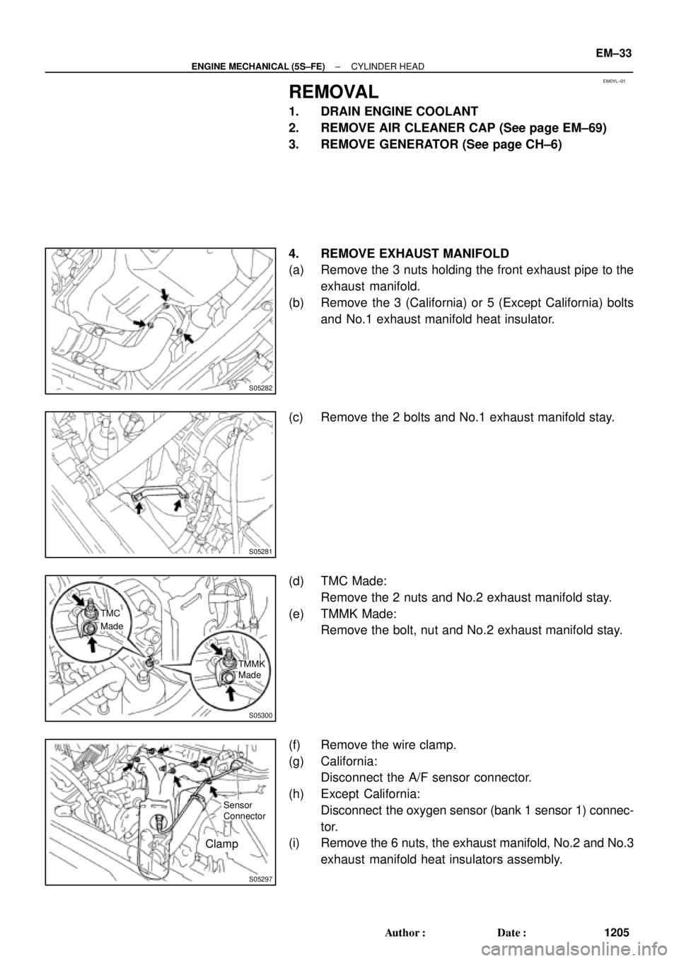
4. REMOVE EXHAUST MANIFOLD
(a) Remove the 3 nuts holding the front exhaust pipe to the
exhaust manifold.
(b) Remove the 3 (California) or 5 (Except California) bolts
and No.1 exhaust manifold heat insulator.
(c) Remove the 2 bolts and No.1 exhaust manifold stay.
(d) TMC Made:
Remove the 2 nuts and No.2 exhaust manifold stay.
(e) TMMK Made:
Remove the bolt, nut and No.2 exhaust manifold stay.
(f) Remove the wire clamp.
(g) California:
Disconnect the A/F sensor connector.
(h) Except California:
Disconnect the oxygen sensor (bank 1 sensor 1) connec-
tor.
(i) Remove the 6 nuts, the exhaust manifold, No.2 and No.3
exhaust manifold heat insulators assembly.
Page 3455 of 4770
S05300
TMC
Made
TMMK
Made
S05282
± ENGINE MECHANICAL (5S±FE)CYLINDER HEAD
EM±63
1235 Author�: Date�:
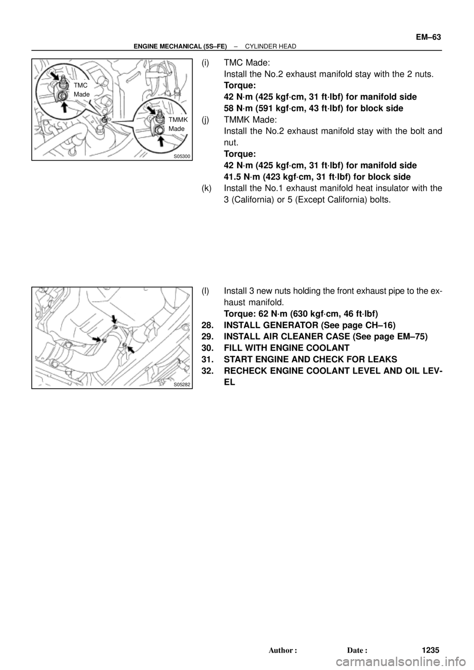
(i) TMC Made:
Install the No.2 exhaust manifold stay with the 2 nuts.
Torque:
42 N´m (425 kgf´cm, 31 ft´lbf) for manifold side
58 N´m (591 kgf´cm, 43 ft´lbf) for block side
(j) TMMK Made:
Install the No.2 exhaust manifold stay with the bolt and
nut.
Torque:
42 N´m (425 kgf´cm, 31 ft´lbf) for manifold side
41.5 N´m (423 kgf´cm, 31 ft´lbf) for block side
(k) Install the No.1 exhaust manifold heat insulator with the
3 (California) or 5 (Except California) bolts.
(l) Install 3 new nuts holding the front exhaust pipe to the ex-
haust manifold.
Torque: 62 N´m (630 kgf´cm, 46 ft´lbf)
28. INSTALL GENERATOR (See page CH±16)
29. INSTALL AIR CLEANER CASE (See page EM±75)
30. FILL WITH ENGINE COOLANT
31. START ENGINE AND CHECK FOR LEAKS
32. RECHECK ENGINE COOLANT LEVEL AND OIL LEV-
EL
Page 3461 of 4770
ENGINE UNIT
EM±69
1241 Author�: Date�:
REMOVAL
1. REMOVE HOOD
2. REMOVE FRONT FENDER APRON SEALS
3. DRAIN ENGINE COOLANT
4. DRAIN ENGINE OIL
5. DISCONNEC")
EM08F±04
S05251
± ENGINE MECHANICAL (5S±FE)ENGINE UNIT
EM±69
1241 Author�: Date�:
REMOVAL
1. REMOVE HOOD
2. REMOVE FRONT FENDER APRON SEALS
3. DRAIN ENGINE COOLANT
4. DRAIN ENGINE OIL
5. DISCONNECT ACCELERATOR CABLE
6. REMOVE AIR CLEANER CAP
(a) Disconnect the IAT sensor connector.
(b) Disconnect the VSV connector for the EVAP
(c) Disconnect the PCV hose from the cylinder head cover.
(d) Disconnect the EVAP hose from the throttle body.
(e) Disconnect the EVAP hose from the VSV.
(f) Disconnect the 2 clamps, and disconnect the air cleaner
cap from the air cleaner case.
(g) Loosen hose clamp, and disconnect the air cleaner hose
from the throttle body.
(h) Remove the air cleaner cap and hose assembly.
7. REMOVE AIR CLEANER CASE
(a) Remove the air filter.
(b) Remove the 3 bolts and air cleaner case.
8. REMOVE BATTERY AND TRAY
9. REMOVE CRUISE CONTROL ACTUATOR
10. REMOVE RADIATOR (See page CO±18)
11. REMOVE FRONT EXHAUST PIPE
(a) Remove the 2 bolts holding the support stay to the sup-
port bracket.
(b) Remove the 2 bolts holding the support bracket to the
front frame.
(c) Remove the 2 bolts and 2 nuts holding the front exhaust
pipe to the center exhaust pipe.
(d) Remove the 3 nuts holding the front exhaust pipe to the
exhaust manifold.
(e) Remove the front exhaust pipe and 2 gaskets.
(f) Remove the nut and support bracket.
12. DISCONNECT CONNECTORS, WIRES, CABLES,
CLAMPS AND HOSES
(a) Disconnect the generator wire.
(b) Disconnect the generator connector.
(c) Disconnect the wire clamp from the generator.
(d) Disconnect the starter cable.
(e) Disconnect the starter connector.
(f) Disconnect the DLC1 from the bracket.
Page 3473 of 4770
± ENGINE MECHANICAL (5S±FE)ENGINE UNIT
EM±81
1253 Author�: Date�:
38. INSTALL AIR CLEANER CAP
(a) Connect the air cleaner hose to the throttle body.
(b) Attach the air cleaner cap to the air cleaner case, and
install the 2 clamps.
(c) Tighten the air cleaner hose clamp.
(d) Connect the PCV hose to the cylinder head cover.
(e) Connect the EVAP hose to the throttle body.
(f) Connect the EVAP hose to the VSV.
(g) Connect the IAT sensor connector.
(h) Connect the VSV connector for the EVAP.
39. CONNECT ACCELERATOR CABLE
40. INSTALL ENGINE FENDER APRON SEALS
41. INSTALL HOOD
42. FILL ENGINE WITH OIL
43. FILL WITH ENGINE COOLANT
44. START ENGINE AND CHECK FOR LEAKS
45. RECHECK ENGINE COOLANT AND OIL LEVELS
Page 3510 of 4770
VALVE CLEARANCE
1290 Author�: Date�:
VALVE CLEARANCE
INSPECTION
HINT:
Inspect and adjust the val")
EM04K±04
P18805
P13074
RH EX
RH IN
LH IN
LH EX 13
6
23
1
6
2Front EM±4
± ENGINE MECHANICAL (1MZ±FE)VALVE CLEARANCE
1290 Author�: Date�:
VALVE CLEARANCE
INSPECTION
HINT:
Inspect and adjust the valve clearance when the engine is cold.
1. REMOVE RH FENDER APRON SEAL
2. DRAIN ENGINE COOLANT
3. REMOVE V±BANK COVER
(a) Using a 5 mm hexagon wrench, remove the 2 nuts.
(b) Disconnect the 2 clips, and remove the cover.
4. REMOVE HIGH±TENSION CODE SET
(See page IG±7)
5. REMOVE AIR INTAKE CHAMBER ASSEMBLY
(See page EM±32)
6. REMOVE IGNITION COILS
7. DISCONNECT RADIATOR HOSE FROM WATER
OUTLET
8. REMOVE CYLINDER HEAD COVERS
(See page EM±32)
9. SET NO.1 CYLINDER TO TDC/COMPRESSION
(a) Turn the crankshaft pulley, and align its groove with the
timing mark º0º of the No.1 timing belt cover.
(b) Check that the valve lifters on the No.1 (IN and EX) are
loose.
If not, turn the crankshaft 1 revolution (360°) and align the mark
as above.
10. INSPECT VALVE CLEARANCE
(a) Check only those valves indicated in the illustration.
(1) Using a feeler gauge, measure the clearance be-
tween the valve lifter and camshaft.
(2) Record out of specification valve clearance mea-
surements. They will be used later to determine the
required replacement adjusting shim.
Valve clearance (Cold):
Intake0.15 ± 0.25 mm (0.006 ± 0.010 in.)
Exhaust0.25 ± 0.35 mm (0.010 ± 0.014 in.)
Page 3513 of 4770
P12979
SST (A)
SST (B)
± ENGINE MECHANICAL (1MZ±FE)VALVE CLEARANCE
EM±7
1293 Author�: Date�:
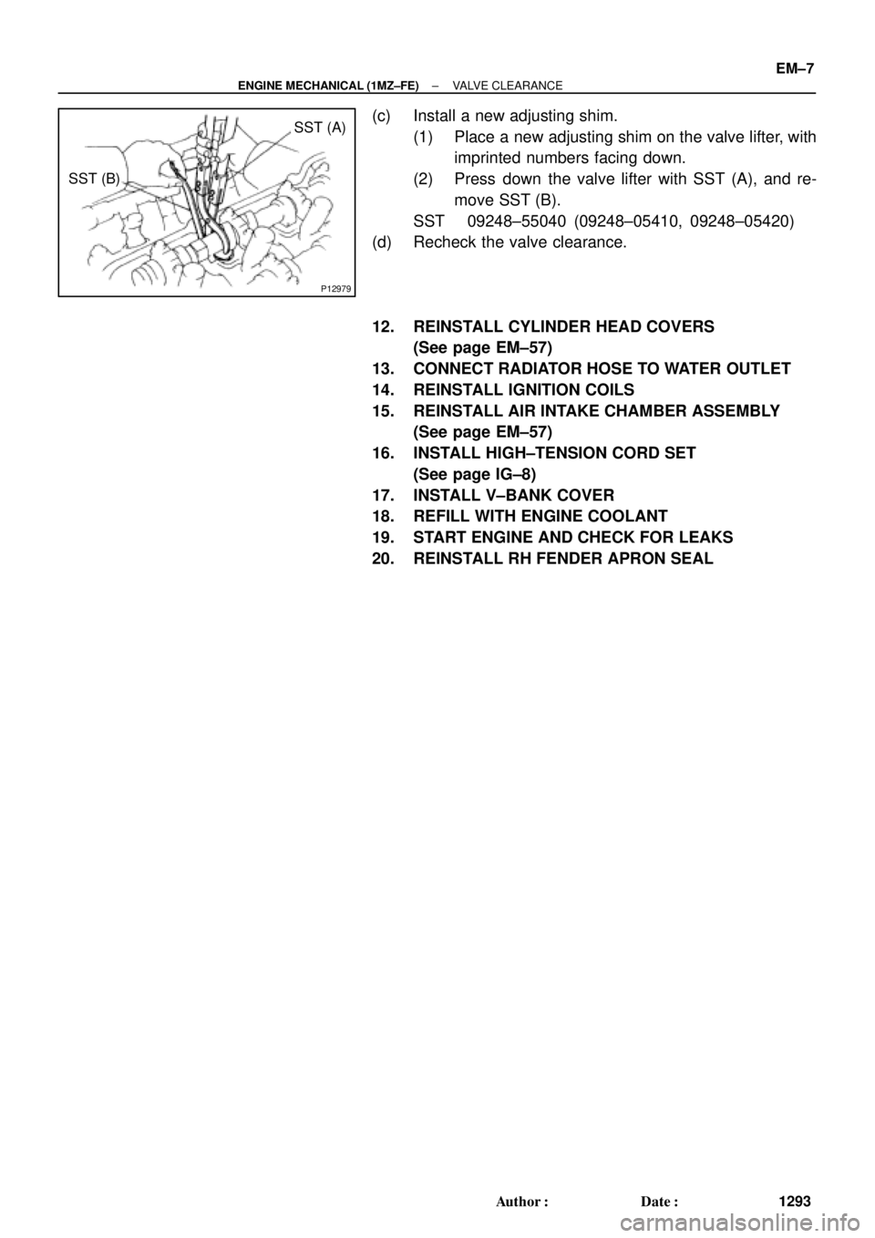
(c) Install a new adjusting shim.
(1) Place a new adjusting shim on the valve lifter, with
imprinted numbers facing down.
(2) Press down the valve lifter with SST (A), and re-
move SST (B).
SST 09248±55040 (09248±05410, 09248±05420)
(d) Recheck the valve clearance.
12. REINSTALL CYLINDER HEAD COVERS
(See page EM±57)
13. CONNECT RADIATOR HOSE TO WATER OUTLET
14. REINSTALL IGNITION COILS
15. REINSTALL AIR INTAKE CHAMBER ASSEMBLY
(See page EM±57)
16. INSTALL HIGH±TENSION CORD SET
(See page IG±8)
17. INSTALL V±BANK COVER
18. REFILL WITH ENGINE COOLANT
19. START ENGINE AND CHECK FOR LEAKS
20. REINSTALL RH FENDER APRON SEAL
Page 3519 of 4770
EM04N±03
A06654
RH Fender Apron Seal
Generator Drive Belt Engine Moving
Control Rod
RH Engine Mounting Stay
No.2 RH Engine
Mounting Bracket
Ground Strap PS Pump Drive Belt
Engine Coolant Reservoir Hose
: Specified torqueNo.2 RH Engine
Mounting Stay (M/T)
64 (650, 47)
32 (320, 23)
64 (650, 47)
N´m (kgf´cm, ft´lbf)
± ENGINE MECHANICAL (1MZ±FE)TIMING BELT
EM±13
1299 Author�: Date�:
TIMING BELT
COMPONENTS
Page 3521 of 4770
EM04O±04
P18754
P18816
P18817
SST
P18819
SST
± ENGINE MECHANICAL (1MZ±FE)TIMING BELT
EM±15
1301 Author�: Date�:
REMOVAL
1. REMOVE RH FRONT WHEEL
2. REMOVE RH FENDER APRON SEAL
3. REMOVE GENERATOR DRIVE BELT
(See page CH±6)
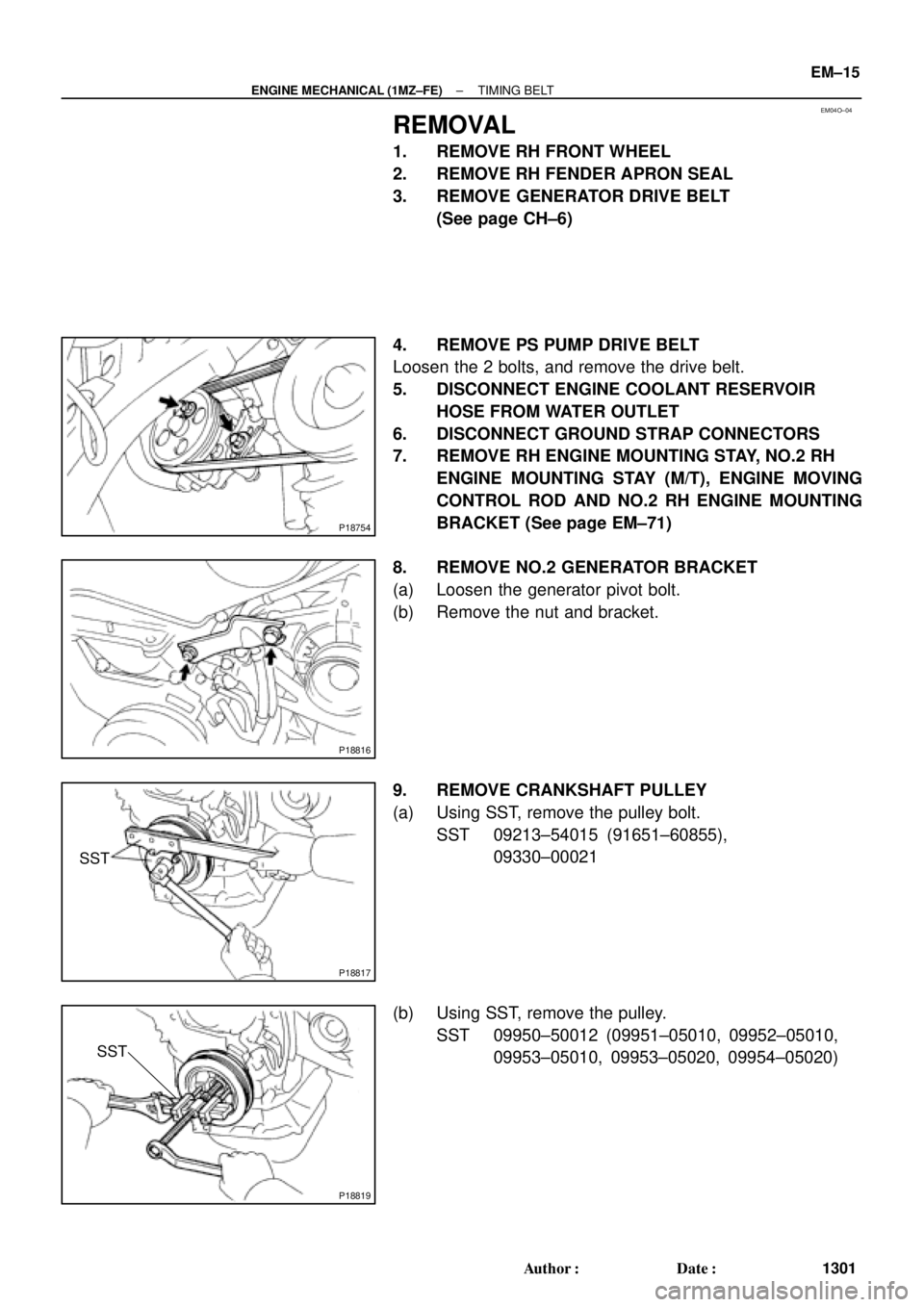
4. REMOVE PS PUMP DRIVE BELT
Loosen the 2 bolts, and remove the drive belt.
5. DISCONNECT ENGINE COOLANT RESERVOIR
HOSE FROM WATER OUTLET
6. DISCONNECT GROUND STRAP CONNECTORS
7. REMOVE RH ENGINE MOUNTING STAY, NO.2 RH
ENGINE MOUNTING STAY (M/T), ENGINE MOVING
CONTROL ROD AND NO.2 RH ENGINE MOUNTING
BRACKET (See page EM±71)
8. REMOVE NO.2 GENERATOR BRACKET
(a) Loosen the generator pivot bolt.
(b) Remove the nut and bracket.
9. REMOVE CRANKSHAFT PULLEY
(a) Using SST, remove the pulley bolt.
SST 09213±54015 (91651±60855),
09330±00021
(b) Using SST, remove the pulley.
SST 09950±50012 (09951±05010, 09952±05010,
09953±05010, 09953±05020, 09954±05020)