Page 4029 of 4770

USA:
Standard indicat")
SS0B0±05
± SERVICE SPECIFICATIONSBODY ELECTRICAL
SS±67
230 Author�: Date�:
BODY ELECTRICAL
SERVICE DATA
TURN SIGNAL FLASHER
Flashes/ Minute60 ± 120
SPEEDOMETER (ON±VEHICLE)
USA:
Standard indication (mph)Allowable range (mph)
2018 ± 24
4038 ± 44
6056 ± 66
8078 ± 88
10098 ± 110
120118 ± 132
CANADA:
Standard indication (km/h)Allowable range (km/h)
2017 ± 24
4038 ± 46
6057.5 ± 67
8077 ± 88
10096 ± 109
120115 ± 130
140134 ± 151.5
160153 ± 173
TACHOMETER (ON±VEHICLE)/ DC 13.5 V 25 °C at (77 °F)
Standard indicationAllowable range
700630 ± 770
1,000900 ± 1,100
2,0001,850 ± 2,150
3,0002,800 ± 3,200
4,0003,800 ± 4,200
5,0004,800 ± 5,200
6,0005,750 ± 6,250
7,0006,700 ± 7,300
FUEL RECEIVER GAUGE
A ± BApprox. 126.2 W
A ± CApprox. 280.5 W
B ± CApprox. 154.3 W
FUEL SENDER GAUGE
Float position mm (in.)Resistance (W)
F: Approx. ±91.1 (±3.587)Approx. 3.0
1/2: Approx. ±34.2 (±1.346)Approx. 31.7
E: Approx. 30.8 (1.213)Approx. 110.0
ENGINE COOLANT TEMPERATURE RECEIVER GAUGE (Resistance)
A ± BApprox. 175.7 W
A ± CApprox. 54.0 W
Page 4030 of 4770
SS±68
± SERVICE SPECIFICATIONSBODY ELECTRICAL
231 Author�: Date�:
B ± CApprox. 229.7 W
ENGINE COOLANT TEMPERATURE SENDER GAUGE (Resistance)
Temperature °C (°F)Resistance (W)
50 (122.0)274
120 (248.0)26.4
Page 4066 of 4770
SF0DP±03
B01283
S05534
Water
Bypass
Hose
Water
Bypass
HoseAir
Hose SF±32
± SFI (5S±FE)THROTTLE BODY
1465 Author�: Date�:
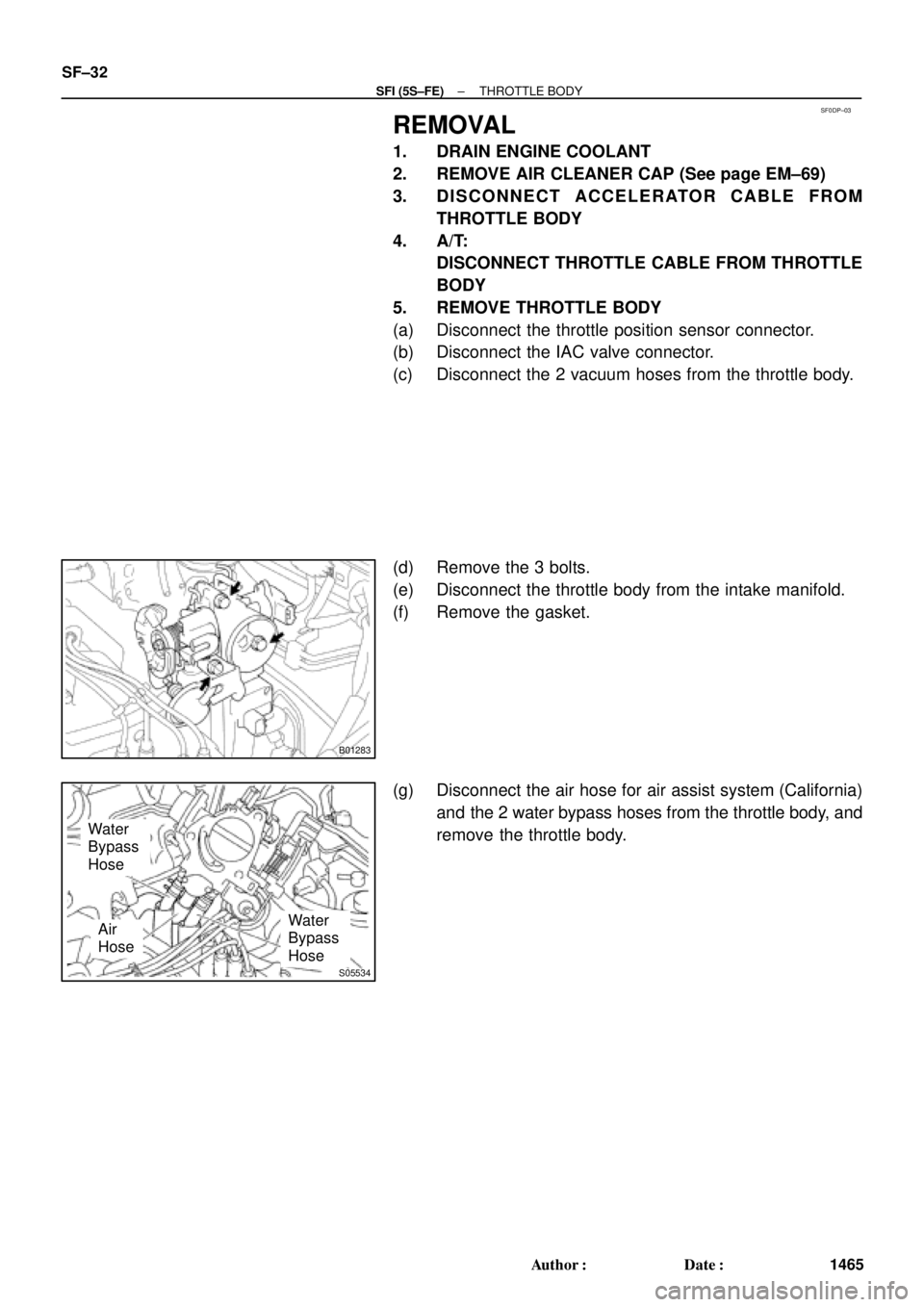
REMOVAL
1. DRAIN ENGINE COOLANT
2. REMOVE AIR CLEANER CAP (See page EM±69)
3. DISCONNECT ACCELERATOR CABLE FROM
THROTTLE BODY
4. A/T:
DISCONNECT THROTTLE CABLE FROM THROTTLE
BODY
5. REMOVE THROTTLE BODY
(a) Disconnect the throttle position sensor connector.
(b) Disconnect the IAC valve connector.
(c) Disconnect the 2 vacuum hoses from the throttle body.
(d) Remove the 3 bolts.
(e) Disconnect the throttle body from the intake manifold.
(f) Remove the gasket.
(g) Disconnect the air hose for air assist system (California)
and the 2 water bypass hoses from the throttle body, and
remove the throttle body.
Page 4068 of 4770
SF0DR±03
S05534
(a)
(c)
(b)
B01283
SF±34
± SFI (5S±FE)THROTTLE BODY
1467 Author�: Date�:
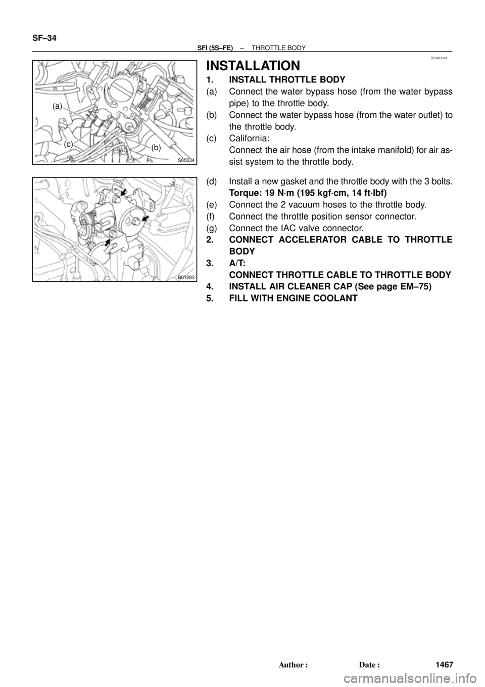
INSTALLATION
1. INSTALL THROTTLE BODY
(a) Connect the water bypass hose (from the water bypass
pipe) to the throttle body.
(b) Connect the water bypass hose (from the water outlet) to
the throttle body.
(c) California:
Connect the air hose (from the intake manifold) for air as-
sist system to the throttle body.
(d) Install a new gasket and the throttle body with the 3 bolts.
Torque: 19 N´m (195 kgf´cm, 14 ft´lbf)
(e) Connect the 2 vacuum hoses to the throttle body.
(f) Connect the throttle position sensor connector.
(g) Connect the IAC valve connector.
2. CONNECT ACCELERATOR CABLE TO THROTTLE
BODY
3. A/T:
CONNECT THROTTLE CABLE TO THROTTLE BODY
4. INSTALL AIR CLEANER CAP (See page EM±75)
5. FILL WITH ENGINE COOLANT
Page 4082 of 4770
SF0E5±03
B06361
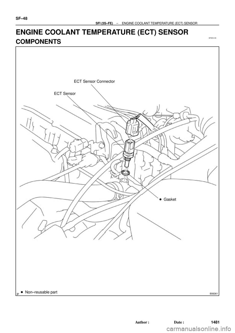
ECT Sensor Connector
ECT Sensor
� Gasket
� Non±reusable part
SF±48
± SFI (5S±FE)ENGINE COOLANT TEMPERATURE (ECT) SENSOR
1481 Author�: Date�:
ENGINE COOLANT TEMPERATURE (ECT) SENSOR
COMPONENTS
Page 4083 of 4770
SF0E6±03
S01196S01699Z17274
Ohmmeter
Resistance kW
Temperature °C (°F) Acceptable 30
20
10
5
3
2
1
0.5
0.3
0.2
0.1
40 ±20 0 20 60 80 100
(212) (176) (140) (104) (68) (32) (±4)
± SFI (5S±FE)ENGINE COOLANT TEMPERATURE (ECT) SENSOR
SF±49
1482 Author�: Date�:
INSPECTION
1. DRAIN ENGINE COOLANT
2. REMOVE ECT SENSOR
3. INSPECT ECT SENSOR
Using an ohmmeter, measure the resistance between the ter-
minals.
Resistance: Refer to the graph
If the resistance is not as specified, replace the ECT sensor.
4. REINSTALL ECT SENSOR
5. REFILL WITH ENGINE COOLANT
Page 4139 of 4770
SF07V±03
S04506
S06123
(a)
(b)
(d) (e)
(c)
S04527
EGR Gas Temperature
Sensor Bracket
± SFI (1MZ±FE)THROTTLE BODY
SF±39
1538 Author�: Date�:
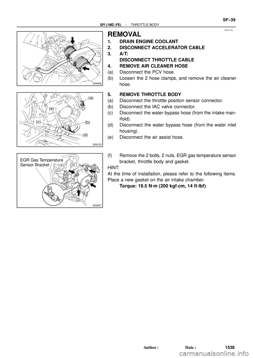
REMOVAL
1. DRAIN ENGINE COOLANT
2. DISCONNECT ACCELERATOR CABLE
3. A/T:
DISCONNECT THROTTLE CABLE
4. REMOVE AIR CLEANER HOSE
(a) Disconnect the PCV hose.
(b) Loosen the 2 hose clamps, and remove the air cleaner
hose.
5. REMOVE THROTTLE BODY
(a) Disconnect the throttle position sensor connector.
(b) Disconnect the IAC valve connector.
(c) Disconnect the water bypass hose (from the intake man-
ifold).
(d) Disconnect the water bypass hose (from the water inlet
housing).
(e) Disconnect the air assist hose.
(f) Remove the 2 bolts, 2 nuts, EGR gas temperature sensor
bracket, throttle body and gasket.
HINT:
At the time of installation, please refer to the following items.
Place a new gasket on the air intake chamber.
Torque: 19.5 N´m (200 kgf´cm, 14 ft´lbf)
Page 4163 of 4770
SF08I±03
S04759
ECT Switch19 mm
Deep Socket
Wrench
Gasket
S01196S01699Z17274
Ohmmeter
Resistance kW
Temperature °C (°F) Acceptable 30
20
10
5
3
2
1
0.5
0.3
0.2
0.1
40 ±20 0 20 60 80 100
(212) (176) (140) (104) (68) (32) (±4)
± SFI (1MZ±FE)ENGINE COOLANT TEMPERATURE (ECT) SENSOR
SF±63
1562 Author�: Date�:
ENGINE COOLANT
TEMPERATURE (ECT) SENSOR
INSPECTION
1. DRAIN ENGINE COOLANT
2. REMOVE ECT SENSOR
(a) Disconnect the ECT sensor connector.
(b) Using a 19 mm deep socket wrench, remove the ECT
sensor and gasket.
3. INSPECT ECT SENSOR
Using an ohmmeter, measure the resistance between the ter-
minals.
Resistance: Refer to the graph
If the resistance is not as specified, replace the ECT sensor.
4. REINSTALL ECT SENSOR
(a) Install a new gasket to the ECT sensor.
(b) Using a 19 mm deep socket, install the ECT sensor.
Torque: 20 N´m (200 kgf´cm, 14 ft´lbf)
(c) Connect the ECT sensor connector.
5. REFILL WITH ENGINE COOLANT

 Acceptable 30
20
10
5
3
2
1
0.5
0.3
0.2
0.1
40 ±20 0 20 60 80 100
(212) (176) (140) (104) (68) (32) (±4)
± SFI (5S±FE)ENGI")
 Acceptable 30
20
10
5
3
2
1
0.5
0.3
0.2
0.1
40 ±20 0 20 60 80 100
(212) (176")