Page 3174 of 4770
H01017H02139AB0118AB0119R13006H01085H02217
P/T Squib (LH)
Airbag
Sensor
Assembly
PL+
PL±
ACC
or
DTC B0138/72ON " u
E1
Tc DLC1
DI±754
± DIAGNOSTICSSUPPLEMENTAL RESTRAINT SYSTEM
989 Author�: Date�:
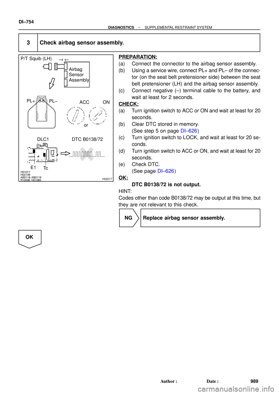
3 Check airbag sensor assembly.
PREPARATION:
(a) Connect the connector to the airbag sensor assembly.
(b) Using a service wire, connect PL+ and PL± of the connec-
tor (on the seat belt pretensioner side) between the seat
belt pretensioner (LH) and the airbag sensor assembly.
(c) Connect negative (±) terminal cable to the battery, and
wait at least for 2 seconds.
CHECK:
(a) Turn ignition switch to ACC or ON and wait at least for 20
seconds.
(b) Clear DTC stored in memory.
(See step 5 on page DI±626)
(c) Turn ignition switch to LOCK, and wait at least for 20 se-
conds.
(d) Turn ignition switch to ACC or ON, and wait at least for 20
seconds.
(e) Check DTC.
(See page DI±626)
OK:
DTC B0138/72 is not output.
HINT:
Codes other than code B0138/72 may be output at this time, but
they are not relevant to this check.
NG Replace airbag sensor assembly.
OK
Page 3175 of 4770
AB0118
R13006AB0119H01018
H01085H01222
"u
E1TcACC ON
or Airbag
Sensor
Assembly P/T Squib (LH)
DTC B0138/72 DLC1
± DIAGNOSTICSSUPPLEMENTAL RESTRAINT SYSTEM
DI±755
990 Author�: Date�:
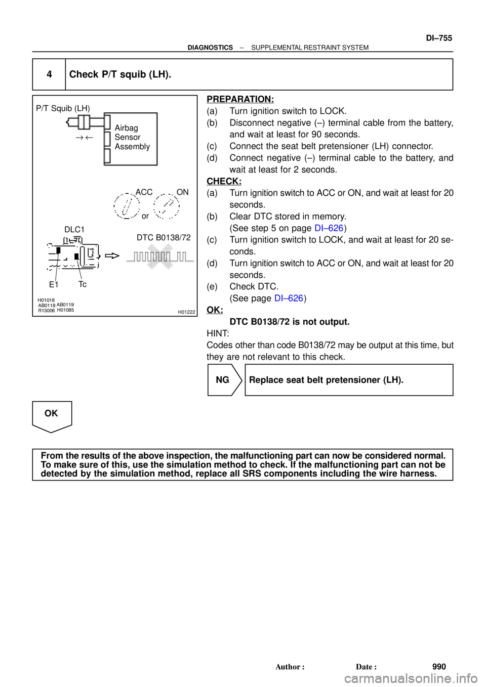
4 Check P/T squib (LH).
PREPARATION:
(a) Turn ignition switch to LOCK.
(b) Disconnect negative (±) terminal cable from the battery,
and wait at least for 90 seconds.
(c) Connect the seat belt pretensioner (LH) connector.
(d) Connect negative (±) terminal cable to the battery, and
wait at least for 2 seconds.
CHECK:
(a) Turn ignition switch to ACC or ON, and wait at least for 20
seconds.
(b) Clear DTC stored in memory.
(See step 5 on page DI±626)
(c) Turn ignition switch to LOCK, and wait at least for 20 se-
conds.
(d) Turn ignition switch to ACC or ON, and wait at least for 20
seconds.
(e) Check DTC.
(See page DI±626)
OK:
DTC B0138/72 is not output.
HINT:
Codes other than code B0138/72 may be output at this time, but
they are not relevant to this check.
NG Replace seat belt pretensioner (LH).
OK
From the results of the above inspection, the malfunctioning part can now be considered normal.
To make sure of this, use the simulation method to check. If the malfunctioning part can not be
detected by the simulation method, replace all SRS components including the wire harness.
Page 3208 of 4770
H01026H06508H06509
LOCK
Airbag Sensor
Assembly
P Squib
D Squib
P/T Squib (LH)
Side Squib (LH)
P/T Squib (RH)
Side Squib (RH)Spiral
Cable
Side Airbag
Sensor (LH)
Side Airbag
Sensor (RH) Front Airbag
Sensor (LH) Front Airbag
Sensor (RH)
DI±788
± DIAGNOSTICSSUPPLEMENTAL RESTRAINT SYSTEM
1023 Author�: Date�:
INSPECTION PROCEDURE
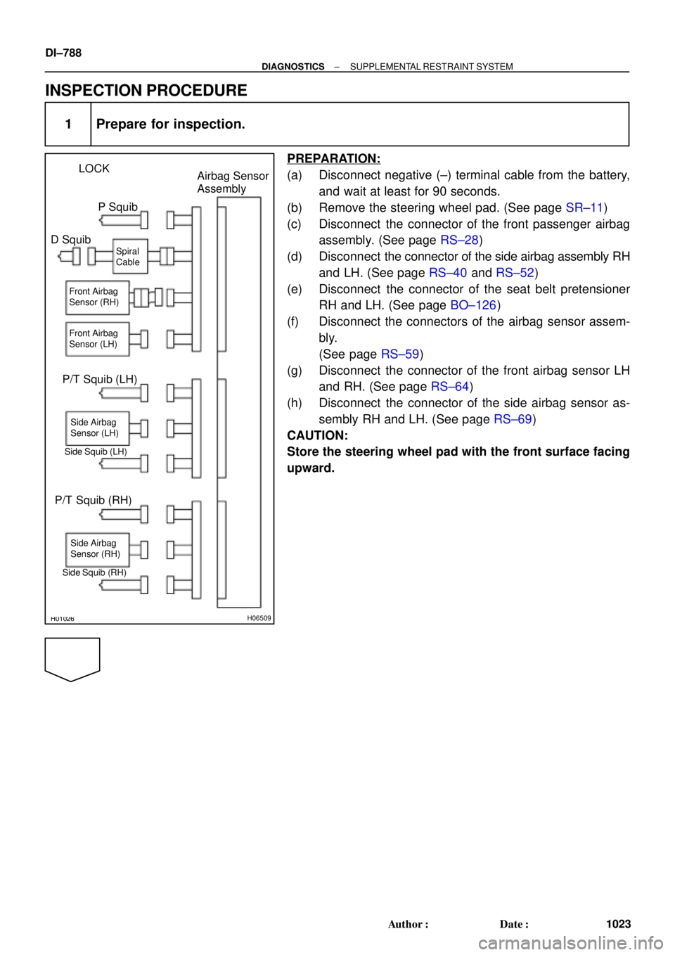
1 Prepare for inspection.
PREPARATION:
(a) Disconnect negative (±) terminal cable from the battery,
and wait at least for 90 seconds.
(b) Remove the steering wheel pad. (See page SR±11)
(c) Disconnect the connector of the front passenger airbag
assembly. (See page RS±28)
(d) Disconnect the connector of the side airbag assembly RH
and LH. (See page RS±40 and RS±52)
(e) Disconnect the connector of the seat belt pretensioner
RH and LH. (See page BO±126)
(f) Disconnect the connectors of the airbag sensor assem-
bly.
(See page RS±59)
(g) Disconnect the connector of the front airbag sensor LH
and RH. (See page RS±64)
(h) Disconnect the connector of the side airbag sensor as-
sembly RH and LH. (See page RS±69)
CAUTION:
Store the steering wheel pad with the front surface facing
upward.
Page 3209 of 4770
AB0119H01298H01299
Airbag Sensor Assembly
ON
ACC
IG2
(+) (±)
H01249
ON
± DIAGNOSTICSSUPPLEMENTAL RESTRAINT SYSTEM
DI±789
1024 Author�: Date�:
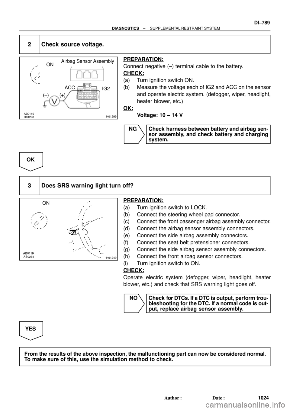
2 Check source voltage.
PREPARATION:
Connect negative (±) terminal cable to the battery.
CHECK:
(a) Turn ignition switch ON.
(b) Measure the voltage each of IG2 and ACC on the sensor
and operate electric system. (defogger, wiper, headlight,
heater blower, etc.)
OK:
Voltage: 10 ± 14 V
NG Check harness between battery and airbag sen-
sor assembly, and check battery and charging
system.
OK
3 Does SRS warning light turn off?
PREPARATION:
(a) Turn ignition switch to LOCK.
(b) Connect the steering wheel pad connector.
(c) Connect the front passenger airbag assembly connector.
(d) Connect the airbag sensor assembly connectors.
(e) Connect the side airbag assembly connectors.
(f) Connect the seat belt pretensioner connectors.
(g) Connect the side airbag sensor assembly connectors.
(h) Connect the front airbag sensor connectors.
(i) Turn ignition switch to ON.
CHECK:
Operate electric system (defogger, wiper, headlight, heater
blower, etc.) and check that SRS warning light goes off.
NO Check for DTCs. If a DTC is output, perform trou-
bleshooting for the DTC. If a normal code is out-
put, replace airbag sensor assembly.
YES
From the results of the above inspection, the malfunctioning part can now be considered normal.
To make sure of this, use the simulation method to check.
Page 3396 of 4770
EM07Z±03
S05289
(c)
(d) (e)
S05590
Turn
P03443
1 11 122
33 EM±4
± ENGINE MECHANICAL (5S±FE)VALVE CLEARANCE
1176 Author�: Date�:
VALVE CLEARANCE
INSPECTION
HINT:
Inspect and adjust the valve clearance when the engine is cold.
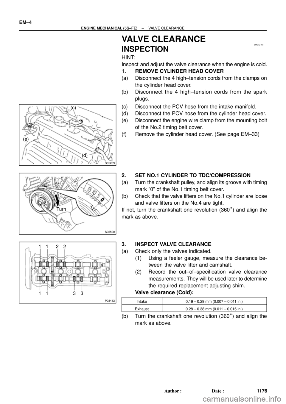
1. REMOVE CYLINDER HEAD COVER
(a) Disconnect the 4 high±tension cords from the clamps on
the cylinder head cover.
(b) Disconnect the 4 high±tension cords from the spark
plugs.
(c) Disconnect the PCV hose from the intake manifold.
(d) Disconnect the PCV hose from the cylinder head cover.
(e) Disconnect the engine wire clamp from the mounting bolt
of the No.2 timing belt cover.
(f) Remove the cylinder head cover. (See page EM±33)
2. SET NO.1 CYLINDER TO TDC/COMPRESSION
(a) Turn the crankshaft pulley, and align its groove with timing
mark º0º of the No.1 timing belt cover.
(b) Check that the valve lifters on the No.1 cylinder are loose
and valve lifters on the No.4 are tight.
If not, turn the crankshaft one revolution (360°) and align the
mark as above.
3. INSPECT VALVE CLEARANCE
(a) Check only the valves indicated.
(1) Using a feeler gauge, measure the clearance be-
tween the valve lifter and camshaft.
(2) Record the out±of±specification valve clearance
measurements. They will be used later to determine
the required replacement adjusting shim.
Valve clearance (Cold):
Intake0.19 ± 0.29 mm (0.007 ± 0.011 in.)
Exhaust0.28 ± 0.38 mm (0.011 ± 0.015 in.)
(b) Turn the crankshaft one revolution (360°) and align the
mark as above.
Page 3398 of 4770
P13989
SST (A)
SST (B)
S05289
(b)
(c)
(d) EM±6
± ENGINE MECHANICAL (5S±FE)VALVE CLEARANCE
1178 Author�: Date�:
Exhaust: N = T + (A ± 0.33 mm (0.013 in.))
(3) Select a new shim with a thickness as close as pos-
sible to the calculated value.
HINT:
Shims are available in 17 sizes in increments of 0.05 mm
(0.0020 in.), from 2.50 mm (0.0984 in.) to 3.30 mm (0.1299 in.).
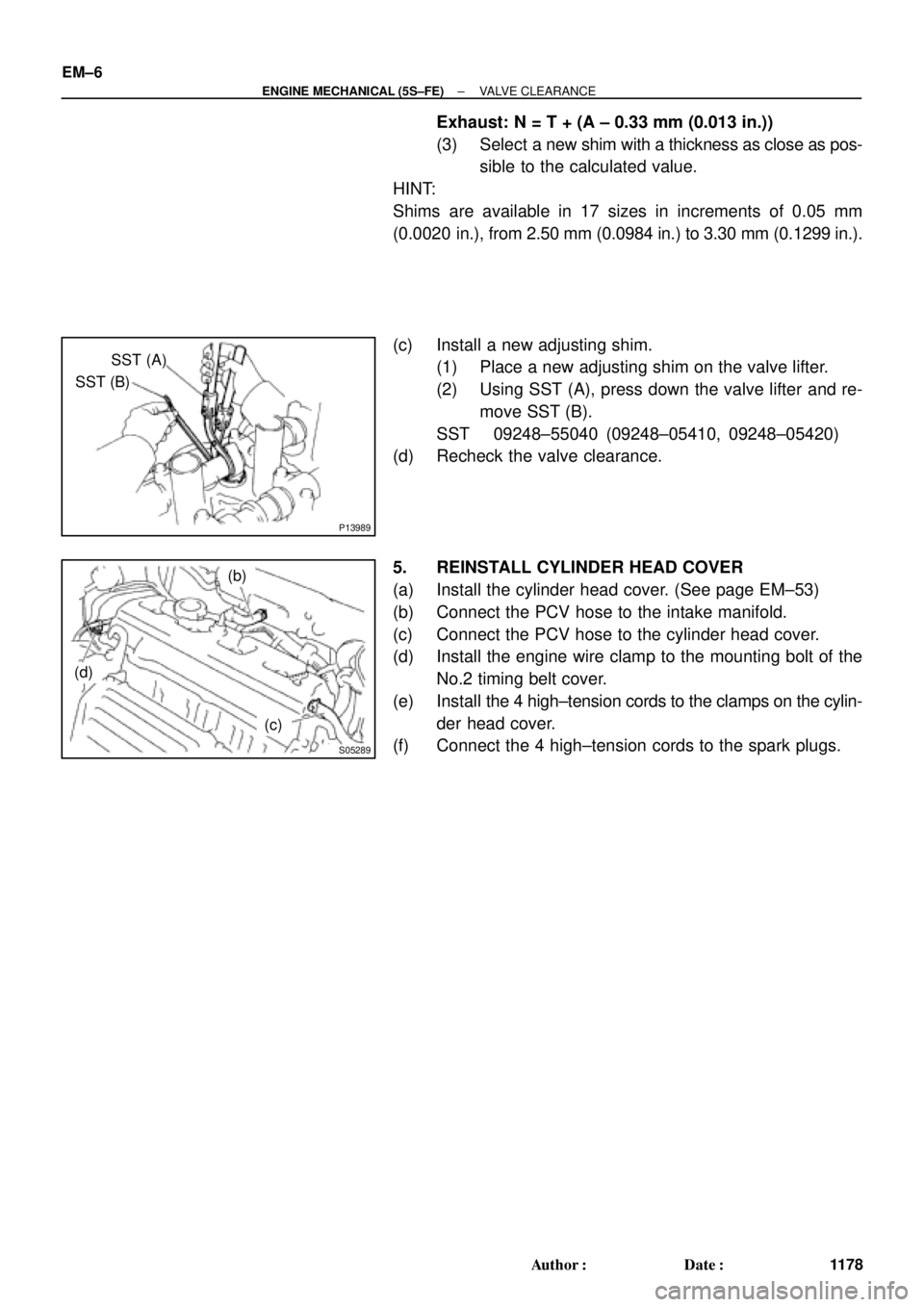
(c) Install a new adjusting shim.
(1) Place a new adjusting shim on the valve lifter.
(2) Using SST (A), press down the valve lifter and re-
move SST (B).
SST 09248±55040 (09248±05410, 09248±05420)
(d) Recheck the valve clearance.
5. REINSTALL CYLINDER HEAD COVER
(a) Install the cylinder head cover. (See page EM±53)
(b) Connect the PCV hose to the intake manifold.
(c) Connect the PCV hose to the cylinder head cover.
(d) Install the engine wire clamp to the mounting bolt of the
No.2 timing belt cover.
(e) Install the 4 high±tension cords to the clamps on the cylin-
der head cover.
(f) Connect the 4 high±tension cords to the spark plugs.
Page 3407 of 4770
EM083±03
S05284
Engine Moving Control Rod
No.2 RH Engine Mounting Bracket
Generator Drive Belt
RH Front Fender Apron SealPS Pump Drive BeltGround Strap Connector
N´m (kgf´cm, ft´lbf)
52 (530, 38)64 (650, 47)
64 (650, 47)
: Specified torque
± ENGINE MECHANICAL (5S±FE)TIMING BELT
EM±15
1187 Author�: Date�:
TIMING BELT
COMPONENTS
Page 3408 of 4770
S05937
No.2 Timing Belt
Cover
No.1 Timing Belt
Cover
Tension Spring Crankshaft
Pulley
Camshaft Timing Pulley
No.1 Idler Pulley
No.2 Idler Pulley
Oil Pump Pulley
Crankshaft Timing Pulley Wire ClampWire ClampWire ClampSpark Plug High±Tension CordTiming Belt Guide Timing Belt
*
1 Gasket Wire
ClampGenerator Wire
Generator Connector
Generator
Wire
Clamp
N´m (kgf´cm, ft´lbf)
*
2 For use with SST
42 (425, 31)
42 (425, 31)
24 (245, 18)18 (180, 13) 108 (1,100, 80)
54 (550, 40)
*
2
37 (380, 27)
: Specified torque*
1 Gasket
*
1
Replace only if damaged EM±16
± ENGINE MECHANICAL (5S±FE)TIMING BELT
1188 Author�: Date�: