Page 2191 of 4770
, FEWER STATION PRESETS
V08242
� Radio±Tape Player Unit (Built±in Power Amplifier)
Problem with radio wave signals or locati")
I03352
5
RadioEITHER AM OR FM DOES NOT WORK, RECEPTION
POOR (VOLUME FAINT), FEWER STATION PRESETS
V08242
� Radio±Tape Player Unit (Built±in Power Amplifier)
Problem with radio wave signals or location?
Are both AM or FM defective?
Is power for the antenna being output from the radio assembly?
Go to No.15
Does tape player operate normally?
Temporarily install another speaker. Functions OK?
Radio assembly faulty.Poor signals, poor location.
Radio assembly faulty.
Radio assembly faulty.
Speaker faulty.
� Radio±Tape Player Unit (Separate Power Amplifier)
� Radio±Tape Player±CD Player Unit (Separate Power Amplifier)
Problem with radio wave signals or location?
Are both AM and FM defective?
Is power for the antenna being output from the radio assembly?
Go to No.15
Temporarily install another speaker. Functions OK?
Hiss noise from speaker?Poor signals, poor location.
Radio assembly faulty.
Radio assembly faulty.
Speaker faulty.
Power amplifier faulty.
Recheck system after repair.
Radio assembly faulty. Recheck system after repair.Ye s NoYe s Ye s Ye s Ye sYe s Ye s Ye s Ye s Ye sYe s
No
No No No No No NoNo No No
Does tape player operate normally?� Radio±CD Player Unit (Built±in Power Amplifier)
� Radio±CD Player Unit (Separate Power Amplifier)
± BODY ELECTRICALAUDIO SYSTEM
BE±97
2317 Author�: Date�:
Page 2192 of 4770
.")
I01472
Is the condition bad in comparison with other vehicle?
6 Radio POOR RECEPTION
An electric wave environment.
Is there any additional installation parts? (Sun shade film,
telephone antenna etc.).Does the condition get better if removing them? Ye s
No
Ye s
No
Check if there is any scratch and breaking in a
wire on the glass antenna and the defogger pattern.
(See page
BE±115)Influence of additional installation parts. No
Repair Ye s
No
No
Is the contact of the plug jack of the radio OK?
Check for contact.
Ye s
No
Does the condition get better by using the outer
antenna? (Such as pillar antenna)Check the radio.
Ye s
No
Ye s
No Is the contact of the antenna terminal on the glass
surface and the defogger terminal?Measure for contact.
Is the continuity of the antenna cord OK? Exchange the antenna cord.
Check the grounding of the antenna, antenna cord,
choke coil and noise filter.Ye s
NG
Grounding failure.
OK
Does the condition get better by exchanging the choke
coil?Exchange the choke coil. Ye s
No
Ye s
Does the condition get better by exchanging the
antenna cord?Exchange the antenna cord.
Exchange the glass.NoYe s
BE±98
± BODY ELECTRICALAUDIO SYSTEM
2318 Author�: Date�:
Page 2205 of 4770

Does the noise occur in a particular place? An electric environment.No
Ye s
Ye")
I01473
23 Noise NOISE OCCURS
Does the noise occur only in the radio? It occurs in the cassette CD. (Go to step 13 or 20)
Does the noise occur in a particular place? An electric environment.No
Ye s
Ye s
Is there any additional installation part around the glass
printed antenna? (Sunshade film, telephone antenna, etc.)Does the noise stop by removing it?
Influence of the film of the noise radiation of
additional installation part.
Does the noise occur even pulling out the antenna cord
from the radio?
Check the radio. No
No
NoNo Ye s
Ye s
Ye s
Does the noise occur even pulling out the antenna
terminal on the glass surface?Mixing into the antenna cable.
Is there any adhesive stuck on the bases of the
antenna terminal, defogger terminal and bus bar?Failure of glass installation. Must plane the butyl rubber.
Does the noise occur even pulling out the defogger
terminal?Interfering noise from the defogger line and choke
coil. Does the condition get better by exchanging the
choke coil? Ye s
Ye s
Ye s No
No
No
Check the grounding of the antenna, antenna cord,
choke coil and noise filter.Exchange the choke coil.
NG
Grounding failure.
Does the condition get better by exchanging the antenna
cord?
Radiates directly to the antenna from the generation
source.Exchange the antenna cord.
NoYe s OK
± BODY ELECTRICALAUDIO SYSTEM
BE±111
2331 Author�: Date�:
Page 2208 of 4770
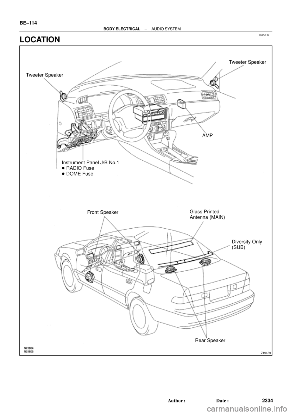
BE0AZ±05
Z19489
Tweeter SpeakerTweeter Speaker
AMP
Instrument Panel J/B No.1
� RADIO Fuse
� DOME Fuse
Front SpeakerGlass Printed
Antenna (MAIN)
Diversity Only
(SUB)
Rear Speaker BE±114
± BODY ELECTRICALAUDIO SYSTEM
2334 Author�: Date�:
LOCATION
Page 3638 of 4770

(f) Remove the bolt, nut, screw and the instrument panel as-
sembly.
23. REMOVE INSTRUMENT PANEL B")
N20994
N20995
N20996
N20997
BO±78
± BODYINSTRUMENT PANEL
2436 Author�: Date�:
2001 CAMRY (RM819U)
(f) Remove the bolt, nut, screw and the instrument panel as-
sembly.
23. REMOVE INSTRUMENT PANEL BRACES
(a) Remove the wire brackets and connector.
(b) Remove the bolt and connector from the No.1 instrument
panel brace.
(c) w/ Wireless Control:
Remove the nut and the wireless control unit from the
No.1 instrument panel brace.
(d) Remove the nut holding the radio antenna to the No.2
instrument panel brace.
(e) Remove a nut and brace mount bracket.
(f) Remove the 6 nuts, 2 bolts and No.1 and No.2 instrument
panel braces.
24. REMOVE INSTRUMENT PANEL REINFORCEMENT
(a) Remove the connectors from the steering column tube.
(b) Remove the 4 wire brackets and connectors.
(c) Remove the 2 nuts and bolt holding the No.1 Junction Box
(J/B) to the reinforcement.
(d) Remove the 4 nuts and the steering column from the rein-
forcement.
(e) Remove the brake pedal spring from the reinforcement
and brake pedal.
(f) Remove the 4 nuts, 3 bolts and the reinforcement.
Page 3688 of 4770

± INTRODUCTIONFOR ALL OF VEHICLES
IN±17
17 Author�: Date�:
2. FOR VEHICLES EQUIPPED WITH A CATALYTIC CONVERTER
CAUTION:
If large amount of unburned gasoline flows into the converter, it may overheat and create a fire haz-
ard. To prevent this, observe the following precautions and explain them to your customer.
(a) Use only unleaded gasoline.
(b) Avoid prolonged idling.
Avoid running the engine at idle speed for more than 20 minutes.
(c) Avoid spark jump test.
(1) Perform spark jump test only when absolutely necessary. Perform this test as rapidly as possible.
(2) While testing, never race the engine.
(d) Avoid prolonged engine compression measurement.
Engine compression tests must be done as rapidly as possible.
(e) Do not run engine when fuel tank is nearly empty.
This may cause the engine to misfire and create an extra load on the converter.
(f) Avoid coasting with ignition turned off.
(g) Do not dispose of used catalyst along with parts contaminated with gasoline or oil.
3. IF VEHICLE IS EQUIPPED WITH MOBILE COMMUNICATION SYSTEM
For vehicles with mobile communication systems such as two±way radios and cellular telephones, observe
the following precautions.
(1) Install the antenna as far as possible away from the ECU and sensors of the vehicle's electronic
system.
(2) Install the antenna feeder at least 20 cm (7.87 in.) away from the ECU and sensors of the ve-
hicle's electronic systems. For details about ECU and sensors locations, refer to the section on
the applicable component.
(3) Avoid winding the antenna feeder together with other wiring as much as possible, and also avoid
running the antenna feeder parallel with other wire harnesses.
(4) Check that the antenna and feeder are correctly adjusted.
(5) Do not install powerful mobile communications system.
Page 4418 of 4770
 are operated.
Poo")
Vehicles with power antennas may exhibit audible electrical noise on weak AM stations when
various electrical accessories (turn signals, rear defogger, cruise control, brakes, etc.) are operated.
Poor antenna grounding can cause this condition.
To eliminate or reduce the intensity of the noise, use the following repair procedure:
AM STATIC NOISE ON VEHICLES WITH POWER ANTENNASPage 1 of 2
OCTOBER 25, 1996
AUDIO
AU002±96
ALL MODELS
REPAIR PROCEDURE:
1. Tune the radio to a strong, static±free AM
station and slowly move the tip of the
antenna mast forward and back
approximately 2 inches (Fig. 1). If static
noise is not heard, go to Step 2. If static
noise is heard during antenna movement,
replace the antenna mast and go to Step 3.
NOTE:Do not touch the antenna mast with
your bare hands. Use a glove or
nonmetallic object to move the
antenna. (If you touch the antenna
with your hands, you will change the
antenna sensitivity).
2. Remove the antenna mast and inspect the
base of the mast for corrosion and damage
(Fig. 2). Clean with 1500 grit sandpaper.
3. Remove the antenna assembly and inspect
the inner fender around the antenna hole
for corrosion (Fig. 3). Clean with 1500 grit
sandpaper.
Fig. 1
Fig. 2
Fig. 3
Inspection
Area
Page:
< prev 1-8 9-16 17-24