Page 225 of 4770
 Put a container under the connection.
(b) Slowly loos")
FUEL SYSTEM
1. When disconnecting the high pressure fuel line, a
large amount of gasoline will spill out, so observe the
following procedures:
(a) Put a container under the connection.
(b) Slowly loosen the connection.
(c) Disconnect the connection.
(d) Plug the connection with a rubber plug.
2. When connecting the flare nut or union bolt on the
high pressure pipe union, observe the following proce±
dures:
Union Bolt Type:
(a) Always use a new gasket.
(b) Tighten the union bolt by hand.
(c) Tighten the union bolt to the specified torque.
Torque: 29 N±m (300 kgf±cm, 22 ft±lbf)
Flare Nut Type:
(s) Apply alight coat of engine oil to the flare and tighten
the flare nut by hand.
(b) Using SST, torque the flare nut.
SST 09631±22020
Torque:
28 N±m (285 kgf±cm, 21 ft±lbf) for fuel pump side
30 N±m (310 kgf±cm, 22 ft±lbf) for others
HINT: Use a torque wrench with a fulcrum length of
30 cm (11.81 in.).
3. Observe the following precautions when removing
and installing the injectors.
(a) Never reuse the O±ring.
(b) When placing a new O±ring on the injector, take care
not to damage it in any way.
(c) Coat a new 0± ring with spindle oil or gasoline before
installing±never use engine, gear or brake oil.
4. Install the injector to delivery pipe and intake manifold
as shown in the illustration.
± 5S±FE ENGINEMFI/SFI SYSTEMEG1±175
Page 251 of 4770
 Type A:
Install the throttle body with the 4 bolts.
Torque: 19 N±m (195 kgf±cm, 14 ft±lbf)
Bolt length:
A 45 mm (1.77 in.)
B 55 mm (2.17 in.)
(d) Type B:
Install the thr")
(c) Type A:
Install the throttle body with the 4 bolts.
Torque: 19 N±m (195 kgf±cm, 14 ft±lbf)
Bolt length:
A 45 mm (1.77 in.)
B 55 mm (2.17 in.)
(d) Type B:
Install the throttle body with the 2 bolts and 2 nuts.
Torque: 19 N±m (195 kgf±cm, 14 ft±lbf)
14. INSTALL AIR CLEANER CAP, RESONATOR AND
AIR CLEANER HOSE
(a) Connect the air cleaner hose to the throttle body.
(b) Install the air cleaner cap together with the resonator
and air cleaner hose.
(c) California only:
Connect the air hose to the air cleaner hose.
(d) Connect the intake air temperature sensor connector.
15. A/T:
CONNECT AND ADJUST THROTTLE CABLE
16. CONNECT AND ADJUST ACCELERATOR CABLE
17. FILL WITH ENGINE COOLANT
Capacity:
6.3 liters (6.7 US qts. 5.5 Imp. qts)
18. CONNECT NEGATIVE (±) TERMINAL CABLE TO
BATTERY (e) Connect the following hoses to the throttle body:
(1) PCV hose
(2) 2 vacuum hoses from EGR vacuum modulator
(3) Vacuum hose from TVV (for EVAP)
(f) Connect the IAC valve connector.
(g) Connect the throttle position sensor connector.
± 5S±FE ENGINEMFI/SFI SYSTEMEG1±201
Page 261 of 4770
 Type A:
Install the throttle body with the 4 bolts.
Torque: 19 N±m (195 kgf±cm, 14 ft±lbf)
Bolt length:
A 45 mm (1.77 in.)
B 55 mm (2.17 in.)
(d) Type B:
Install the throttle body with")
(c) Type A:
Install the throttle body with the 4 bolts.
Torque: 19 N±m (195 kgf±cm, 14 ft±lbf)
Bolt length:
A 45 mm (1.77 in.)
B 55 mm (2.17 in.)
(d) Type B:
Install the throttle body with the 2 bolts and 2 nuts.
Torque: 19 N±m (195 kgf±cm, 14 ft±lbf)
3. INSTALL AIR CLEANER CAP, RESONATOR AND
AIR CLEANER HOSE
(a) Connect the air cleaner hose to the throttle body.
(b) Install the air cleaner cap together with the resonator
and air cleaner hose.
(c) California only:
Connect the air hose to the air cleaner hose.
(d) Connect the intake air temperature sensor connector.
4. A/T:
CONNECT AND ADJUST THROTTLE CABLE
5. CONNECT AND ADJUST ACCELERATOR CABLE
6. FILL WITH ENGINE COOLANT
7. CONNECT NEGATIVE (±) TERMINAL CABLE TO
BATTERY (e) Connect the following hoses to the throttle body:
(1) PCV hose
(2) 2 vacuum hoses from EGR vacuum modulator
(3) Vacuum hose from TVV (for EVAP)
(f) Connect the IAC valve connector.
(g) Connect the throttle position sensor connector.
± 5S±FE ENGINEMFI/SFI SYSTEMEG1±211
Page 296 of 4770
7. TEMPORARILY INSTALL NO.1 IDLER PULLEY AND
TENSION SPRING
(a) Install the pulley with the bolt. Do not tighten the bolt
yet.
HINT: Use bolt 42 mm (1.65 in.) in length.
(b) Install the tension spring.
(c) Pry the pulley toward the left as far as it will go and
tighten the bolt.
(d) Check that the idler pulley moves smoothly.
8. INSTALL TIMING BELT (See page EG1±33)
9. CONNECT NEGATIVE (±) TERMINAL CABLE TO
BATTERY
10. FILL WITH ENGINE COOLANT
(See page EG1±241) 6. INSTALL NO.2 IDLER PULLEY
(a) Install the pulley with the bolt.
Torque: 42 N±m (425 kgf±cm, 31 ft±lbf)
HINT: Use a bolt 35 mm (1.38 in.) in length.
(b) Check that the idler pulley moves smoothly. 4. INSTALL GENERATOR BELT ADJUSTING BAR
Temporarily install the adjusting bar with the bolt.
5. CONNECT LOWER RADIATOR HOSE TO WATER
INLET (f) Install the 2 nuts holding the water pump cover to the
water bypass pipe.
Torque: 8.8 N±m (90 kgf±cm, 78 in.±Ibf)
± 5S±FE ENGINECOOLING SYSTEMEG1±246
Page 324 of 4770

OIL AND FILTER REPLACEMENT
CAUTION:
wProlonged and repeated contact with mineral oil will
result in the removal of natural fats from the skin,
leading to dryness, irritation and dermatitis. In addi±
tion, used engine oil contains potentially harmful
contaminants which may cause skin cancer.
wCare should be taken, therefore, when changing
engine, oil to minimize the frequency and length of
time your skin is exposed to used engine oil. Protec±
tive clothing and gloves that cannot be penetrated
by oil should be worn. The skin should be thorought±
hly washed with soap and water, or use water±less
hand cleaner, to remove any used engine oil. Do not
use gasoline, thinners, or solvents.
wIn order to preserve the environment, used oil and
used oil filter must be disposed of only at designated
disposal sites.
1. DRAIN ENGINE OIL
(a) Remove the oil filler cap.
(b) Remove the oil drain plug, and drain the oil into a
container.
2. REPLACE OIL FILTER
(a) Using SST, remove the oil filter.
SST 09228±06500
(b) Check and clean the oil filter installation surface.
± 5S±FE ENGINELUBRICATION SYSTEMEG1±274
Page 333 of 4770
OIL PUMP INSTALLATION
(See Components for Removal and Installation)
1. INSTALL OIL PUMP
Install a new gasket and the oil pump with the 12
bolts.
Torque: 9.3 N±m (95 kgf±cm, 82 in.±lbf)
HINT: Long bolts are indicated in the illustration.
Bolt length:
Long bolt
35 mm (1.38 in.)
Others
25 mm (0.98 in.)
3. INSTALL CRANKSHAFT TIMING PULLEY
(a) Align the timing pulley set key with the key groove of
the pulley.
(b) Slide on the timing pulley, facing the flange side
inward. 2. INSTALL OIL PUMP PULLEY
(a) Align the cutouts of the pulley and shaft, and slide on
the pulley.
(b) Using SST, install the nut.
SST 09616±30011
Torque: 28 N±m (290 kgf±cm, 21 ft±lbf)
± 5S±FE ENGINELUBRICATION SYSTEMEG1±283
Page 334 of 4770
 Remove any old packing (FIPG) material and be care±
ful not to drop any oil on the contact surfaces of the
oil pan and cylinder block.
wUsing a razor blade and gasket scraper,")
8. INSTALL OIL PAN
(a) Remove any old packing (FIPG) material and be care±
ful not to drop any oil on the contact surfaces of the
oil pan and cylinder block.
wUsing a razor blade and gasket scraper, remove
all the old packing (FIPG) material from the
gasket surfaces and sealing groove.
wThoroughly clean all components to remove all
the loose material.
wUsing a non±residue solvent, clean both sealing
surfaces.
NOTICE: Do not use a solvent which will affect the paint±
ed surfaces.
(b) Apply seal packing to the oil pan as shown in the
illustration.
Seal packing:
Part No.08826 ± 00080 or equivalent
wInstall a nozzle that has been cut to a 3±5 mm
(0.12±0.20 in.) opening.
wParts must be assembled within 5 minutes of
application. Otherwise the material must be re±
moved and reapplied.
wImmediately remove nozzle from the tube and
reinstall cap. 4. INSTALL NO.2 IDLER PULLEY
(a) Install the pulley with the bolt.
Torque: 42 N±m (425 kgf±cm, 31 ft±lbf)
HINT: Use a bolt 35 mm (1.38 in.) in length.
(b) Check that the idler pulley moves smoothly.
5. INSTALL TIMING BELT (See page EG1±33)
6. REMOVE ENGINE SLING DEVICE
7. INSTALL OIL STRAINER
Install a new gasket and the oil strainer with bolt and
nuts.
Torque: 5.4 N±m (55 kgf±cm, 48 in.±lbf)
± 5S±FE ENGINELUBRICATION SYSTEMEG1±284
Page 512 of 4770
33 ENGINEÐ5S±FE ENGINE
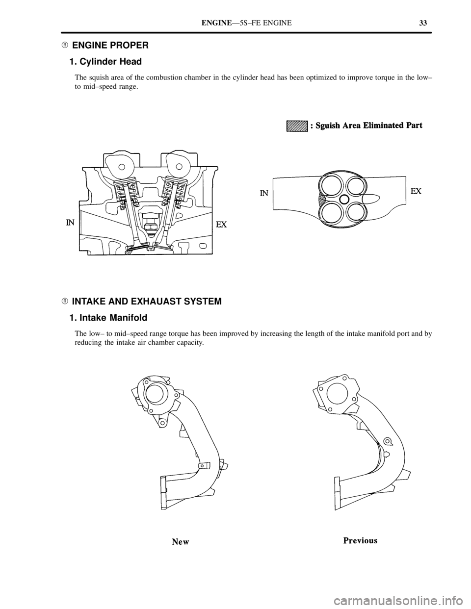
� ENGINE PROPER
1. Cylinder Head
The squish area of the combustion chamber in the cylinder head has been optimized to improve torque in the low±
to mid±speed range.
� INTAKE AND EXHAUAST SYSTEM
1. Intake Manifold
The low± to mid±speed range torque has been improved by increasing the length of the intake manifold port and by
reducing the intake air chamber capacity.
 Install the pulley with the bolt. Do not tighten the bolt
yet.
HINT: Use bolt 42 mm (1.65 in.) in length.
(b) Install the")

1. INSTALL OIL PUMP
Install a new gasket and the oil pump with the 12
bolts.
Torque: 9.3 N±m (95 kgf±cm, 82 in.±lbf)
HINT: Long b")