Page 85 of 4770
9. INSTALL CAMSHAFT TIMING PULLEY
(a) Align the camshaft knock pin with the knock pin
groove of the pulley, and slide on the timing pulley.
(b) Using SST, install the plate washer and bolt.
SST 09249 ± 63010 and 09278 ± 54012
Torque: 37 N±m (380 kgf±cm, 27 ft±lbf)
HINT: Use a torque wrench with a fulcrum length of
340 cm (13.39 in.)8. INSTALL CRANKSHAFT PULLEY
(a) Align the pulley set key with the key groove of the
pulley, and slide on the pulley.
(b) Using SST, install the pulley bolt.
SST 09213±54015 (91651 ±60855)
09330±00021
Torque: 108 N±m (1,100 kgf±cm, 80 ft±lbf)
10. SET No.1 CYLINDER TO TDC/COMPRESSION
(a) Turn the crankshaft pulley, and align its groove with
timing mark ª0º of the No.1 timing belt cover. 7. INSTALL NO.1 TIMING BELT COVER
(a) Install the gasket to the timing belt cover.
(b) Install the timing belt cover with the 4 bolts. 6. INSTALL TIMING BELT GUIDE
Install the guide, facing the cup side outward.
± 5S±FE ENGINEENGINE MECHANICALEG1±35
Page 100 of 4770

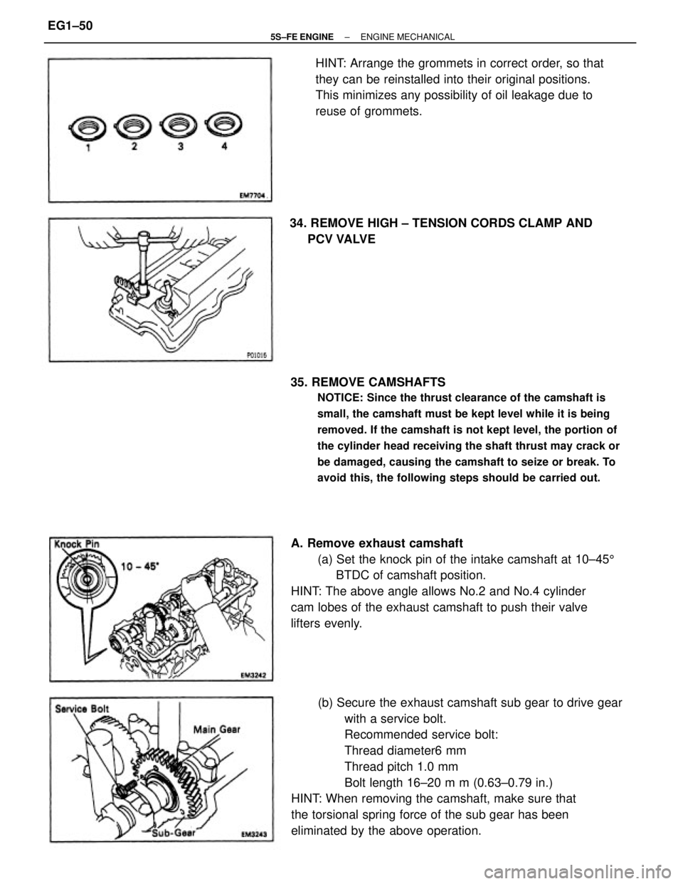
(b) Secure the exhaust camshaft sub gear to drive gear
with a service bolt.
Recommended service bolt:
Thread diameter6 mm
Thread pitch 1.0 mm
Bolt length 16±20 m m (0.63±0.79 in.)
HINT: When removing the camshaft, make sure that
the torsional spring force of the sub gear has been
eliminated by the above operation. 35. REMOVE CAMSHAFTS
NOTICE: Since the thrust clearance of the camshaft is
small, the camshaft must be kept level while it is being
removed. If the camshaft is not kept level, the portion of
the cylinder head receiving the shaft thrust may crack or
be damaged, causing the camshaft to seize or break. To
avoid this, the following steps should be carried out.
A. Remove exhaust camshaft
(a) Set the knock pin of the intake camshaft at 10±455
BTDC of camshaft position.
HINT: The above angle allows No.2 and No.4 cylinder
cam lobes of the exhaust camshaft to push their valve
lifters evenly.HINT: Arrange the grommets in correct order, so that
they can be reinstalled into their original positions.
This minimizes any possibility of oil leakage due to
reuse of grommets.
34. REMOVE HIGH ± TENSION CORDS CLAMP AND
PCV VALVE
± 5S±FE ENGINEENGINE MECHANICALEG1±50
Page 110 of 4770
(d) Check the valve overall length.
Standard overall length:
Intake
97.60 mm (3.8425 in.)
Exhaust
98.45 mm (3.8760 in.)
Minimum overall length:
Intake
97.1 mm (3.823 in.)
Exhaust
98.0 mm (3.858 in.)
If the overall length is less than minimum, replace the
valve.
(b) Check the valve seating position.
Apply a light coat of prussian blue (or white lead) to
the valve face. Lightly press the valve against the
seat. Do not rotate valve.
(c) Check the valve face and seat for the following:
If blue appears 360� around the face, the valve is
concentric. If not, replace the valve. (e) Check the surface of the valve stem tip for wear.
If the valve stem tip is worn, resurface the tip with a
grinder or replace the valve.
NOTICE: Do not grind off more than minimum.
8. INSPECT AND CLEAN VALVE SEATS
(a) Using a 45� carbide cutter, resurface the valve seats.
Remove only enough metal to clean the seats.
± 5S±FE ENGINEENGINE MECHANICALEG1±60
Page 111 of 4770

wIf blue appears 360� around the valve seat, the
guide and face are concentric. If not, resurface
the seat.
wCheck that the seat contact is in the middle of the
valve face with the following width:
1.0 ± 1.4 mm (0.039 ± 0.055 in.)
If not, correct the valve seat as follows:
(1) If the seating is too high on the valve face, use
30� and 45� cutters to correct the seat.
(2) If the seating is too low on the valve face, use
75� and 45� cutters to correct the seat.
9. INSPECT VALVE SPRINGS
(a) Using a steel square, measure the deviation of the
valve spring.
Maximum deviation:
2.0 mm (0.079 in.)
If the deviation is greater than maximum, replace the
valve spring.
(b) Using a vernier caliper, measure the free length of the
valve spring.
Free length:
41.96 ± 41.99 mm (1.6520 ± 1.6531 in.)
If the free length is not as specified, replace the valve
spring. (d) Hand±lap the valve and valve seat with an abrasive
compound.
(e) After hand±lapping, clean the valve and valve seat.
± 5S±FE ENGINEENGINE MECHANICALEG1±61
Page 112 of 4770

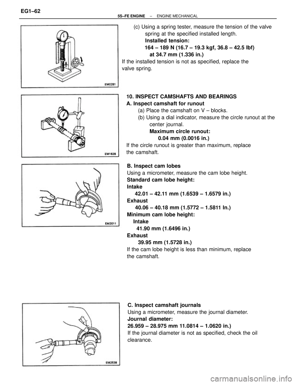
B. Inspect cam lobes
Using a micrometer, measure the cam lobe height.
Standard cam lobe height:
Intake
42.01 ± 42.11 mm (1.6539 ± 1.6579 in.)
Exhaust
40.06 ± 40.18 mm (1.5772 ± 1.5811 In.)
Minimum cam lobe height:
Intake
41.90 mm (1.6496 in.)
Exhaust
39.95 mm (1.5728 in.)
If the cam lobe height is less than minimum, replace
the camshaft. 10. INSPECT CAMSHAFTS AND BEARINGS
A. Inspect camshaft for runout
(a) Place the camshaft on V ± blocks.
(b) Using a dial indicator, measure the circle runout at the
center journal.
Maximum circle runout:
0.04 mm (0.0016 in.)
If the circle runout is greater than maximum, replace
the camshaft.(c) Using a spring tester, measure the tension of the valve
spring at the specified installed length.
Installed tension:
164 ± 189 N (16.7 ± 19.3 kgf, 36.8 ± 42.5 lbf)
at 34.7 mm (1.336 in.)
If the installed tension is not as specified, replace the
valve spring.
C. Inspect camshaft journals
Using a micrometer, measure the journal diameter.
Journal diameter:
26.959 ± 28.975 mm 11.0814 ± 1.0620 in.)
If the journal diameter is not as specified, check the oil
clearance.
± 5S±FE ENGINEENGINE MECHANICALEG1±62
Page 124 of 4770
13. TEMPORARILY INSTALL NO.1 IDLER PULLEY AND
TENSION SPRING
(a) Install the pulley with the bolt. Do not tighten the bolt
yet.
HINT: Use bolt 42 mm (1.65 in.) in length.
(b) Install the tension spring.
(c) Pry the pulley toward the left as far as it will go and
tighten the bolt.
(d) Check that the idler pulley moves smoothly.
14. INSTALL CAMSHAFT TIMING PULLEY AND
TIMING BELT
(See page EG1±33)
15. INSTALL INJECTORS AND DELIVERY PIPE
(a) California:
Install new insulator and grommet to each injector.
(b) Except California:
Install a new grommet to each injector.
(c) California:
Apply a light coat of gasoline to 2 new 0±rings, and
install them to each injector.
(d) Except California:
Apply a light coat of gasoline to a new 0±ring, and
install it to each injector.
(e) While turning the injector left and right, install it to the
delivery pipes. Install the 4 injectors.
± 5S±FE ENGINEENGINE MECHANICALEG1±74
Page 128 of 4770

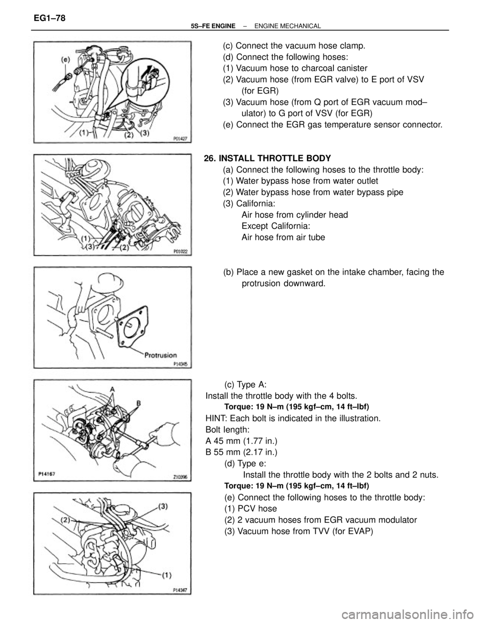
(c) Type A:
Install the throttle body with the 4 bolts.
Torque: 19 N±m (195 kgf±cm, 14 ft±lbf)
HINT: Each bolt is indicated in the illustration.
Bolt length:
A 45 mm (1.77 in.)
B 55 mm (2.17 in.)
(d) Type e:
Install the throttle body with the 2 bolts and 2 nuts.
Torque: 19 N±m (195 kgf±cm, 14 ft±lbf)
(e) Connect the following hoses to the throttle body:
(1) PCV hose
(2) 2 vacuum hoses from EGR vacuum modulator
(3) Vacuum hose from TVV (for EVAP) (c) Connect the vacuum hose clamp.
(d) Connect the following hoses:
(1) Vacuum hose to charcoal canister
(2) Vacuum hose (from EGR valve) to E port of VSV
(for EGR)
(3) Vacuum hose (from Q port of EGR vacuum mod±
ulator) to G port of VSV (for EGR)
(e) Connect the EGR gas temperature sensor connector.
26. INSTALL THROTTLE BODY
(a) Connect the following hoses to the throttle body:
(1) Water bypass hose from water outlet
(2) Water bypass hose from water bypass pipe
(3) California:
Air hose from cylinder head
Except California:
Air hose from air tube
(b) Place a new gasket on the intake chamber, facing the
protrusion downward.
± 5S±FE ENGINEENGINE MECHANICALEG1±78
Page 190 of 4770
Warpage
Cylinder block side
Manifold side
Valve seat
Refacing angle
Contacting angle
Contacting width
SERVICE SPECIFICATIONS
SERVICE DATA
Deviation
Free length
Installed tension et 34.7 mm (1.366 in.) Free length
Installed load at 50.5 mm (1.988 in.)
Inside diameter
Outside diameter (for repair part)
Lifter diameter
Lifter bore diameter
Oil clearance Difference of pressure between each cylinder
Vale face angle
Stem diameter Idler pulley
tension spring Intake
manifold
vacuum
Compression
pressure
Valve guide
bushing
Valve overall length
Stem oil clearance
Margin thickness
Cylinder
head
at idle speed
Valve springet 250 rpm Idle speed
Valve lifter
Warpage Manifold Valve
± 5S±FE ENGINEENGINE MECHANICALEG1±140