Page 4316 of 4770

SR06R±01
R13458
Inscribed Mark
R01149
Round End
R11292
SR±26
± STEERINGPOWER STEERING VANE PUMP
2121 Author�: Date�:
REASSEMBLY
NOTICE:
When using a vise, do not overtighten it.
1. COAT WITH POWER STEERING FLUID
(See page SR±18)
2. INSTALL VANE PUMP SHAFT
3. INSTALL STRAIGHT PINS
Using a plastic hammer, tap in 2 new pins.
NOTICE:
Be careful not to damage the pins.
4. INSTALL CAM RING
Align the holes of the ring and 2 straight pins, and install the ring
with the inscribed mark facing outward.
5. INSTALL VANE PUMP ROTOR
(a) Install the rotor with the inscribed mark facing outward.
(b) Install a new snap ring to the vane pump shaft.
6. INSTALL VANE PLATES
Install the 10 plates with the round end facing outward.
7. INSTALL GASKET
Install a new gasket.
8. INSTALL SIDE PLATE
Align the holes of the plate and 2 straight pins.
9. INSTALL WAVE WASHER
Install the washer so that its protrusions fit into the slots in the
side plate.
10. INSTALL REAR HOUSING
(a) Coat 2 new O±rings with power steering fluid and install
them to the housing.
(b) Torque the 4 bolts.
5S±FE and 1MZ±FE Engines:
Torque: 24 N´m (240 kgf´cm, 17 ft´lbf)
Page 4317 of 4770
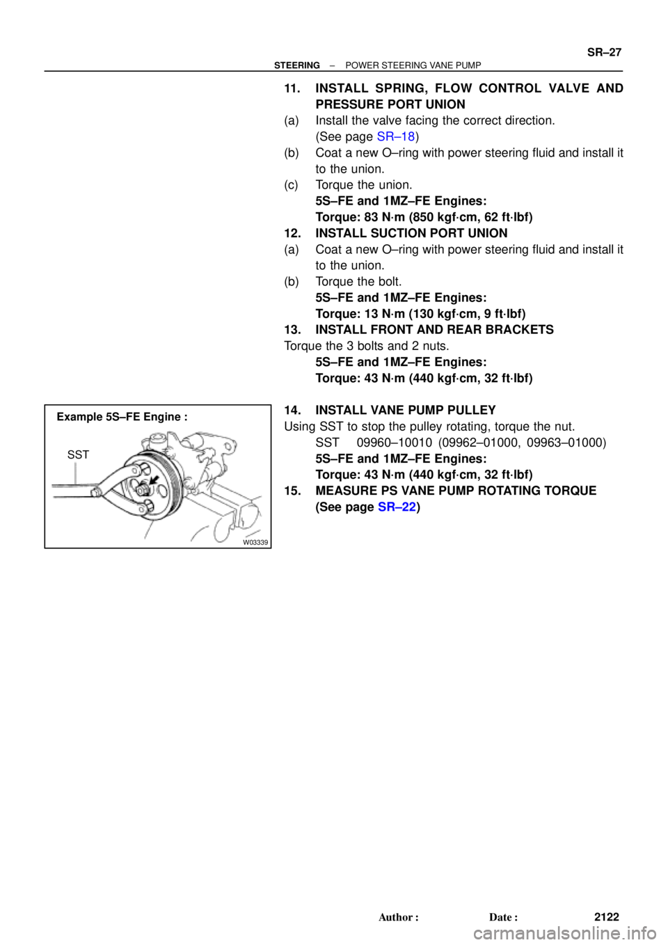
W03339
Example 5S±FE Engine :
SST
± STEERINGPOWER STEERING VANE PUMP
SR±27
2122 Author�: Date�:
11. INSTALL SPRING, FLOW CONTROL VALVE AND
PRESSURE PORT UNION
(a) Install the valve facing the correct direction.
(See page SR±18)
(b) Coat a new O±ring with power steering fluid and install it
to the union.
(c) Torque the union.
5S±FE and 1MZ±FE Engines:
Torque: 83 N´m (850 kgf´cm, 62 ft´lbf)
12. INSTALL SUCTION PORT UNION
(a) Coat a new O±ring with power steering fluid and install it
to the union.
(b) Torque the bolt.
5S±FE and 1MZ±FE Engines:
Torque: 13 N´m (130 kgf´cm, 9 ft´lbf)
13. INSTALL FRONT AND REAR BRACKETS
Torque the 3 bolts and 2 nuts.
5S±FE and 1MZ±FE Engines:
Torque: 43 N´m (440 kgf´cm, 32 ft´lbf)
14. INSTALL VANE PUMP PULLEY
Using SST to stop the pulley rotating, torque the nut.
SST 09960±10010 (09962±01000, 09963±01000)
5S±FE and 1MZ±FE Engines:
Torque: 43 N´m (440 kgf´cm, 32 ft´lbf)
15. MEASURE PS VANE PUMP ROTATING TORQUE
(See page SR±22)
Page 4318 of 4770
SR06S±01
W03361
5S±FE Engine :
1MZ±FE Engine :Pressure Feed Tube
Stopper
Pressure
Feed
StopperTube
W03360
Example 5S±FE Engine :
A
B
W03542
5S±FE Engine :
SST
Fulcrum
Length SR±28
± STEERINGPOWER STEERING VANE PUMP
2123 Author�: Date�:
INSTALLATION
1. INSTALL PRESSURE FEED TUBE
(a) Torque the union bolt with a new gasket.
HINT:
Make sure the stopper of the tube is touching the front bracket,
as shown, then torque the union bolt.
5S±FE and 1MZ±FE Engines:
Torque: 52 N´m (525 kgf´cm, 38 ft´lbf)
(b) Install the oil pressure switch to the union bolt.
5S±FE and 1MZ±FE Engines:
Torque: 21 N´m (210 kgf´cm, 15 ft´lbf)
2. INSTALL PS VANE PUMP ASSEMBLY WITH PRESS-
ER FEED TUBE
Temporarily tighten the 2 (A and B) bolts.
3. INSTALL DRIVE BELT
(a) Adjust drive belt tension.
(See page SR±3)
(b) 5S±FE Engine:
Using SST, torque the A bolt.
SST 09249±63010
Torque: 29 N´m (293 kgf´cm, 21 ft´lbf)
HINT:
Use a torque wrench with a fulcrum length of 300 mm (11.81
in.).
Page 4319 of 4770

W03543
1MZ±FE Engine :
Engine Wire Clamp
Fulcrum
Length
SST
W04221
5S±FE Engine :
1MZ±FE Engine :Fulcrum
Length
SST Pressure
Feed Tube
Fulcrum
LengthSST
± STEERINGPOWER STEERING VANE PUMP
SR±29
2124 Author�: Date�:
(c) 1MZ±FE Engine:
Using SST, torque the A bolt.
SST 09249±63010
Torque: 29 N´m (293 kgf´cm, 21 ft´lbf)
HINT:
�Use a torque wrench with a fulcrum length of 300 mm
(11.81 in.).
�Disconnect the clamp with engine wire.
(d) Torque the B bolt.
5S±FE and 1MZ±FE Engines:
Torque: 43 N´m (440 kgf´cm, 32 ft´lbf)
(e) Connect the connector to the oil pressure switch.
NOTICE:
Be careful for oil on the connector.
4. CONNECT PRESSURE FEED TUBE
(a) Using SST, connect the tube.
SST 09631±22020
5S±FE Engine:
Torque: 32 N´m (326 kgf´cm, 24 ft´lbf)
1MZ±FE Engine:
Torque: 20 N´m (203 kgf´cm, 15 ft´lbf)
HINT:
�Use a torque wrench with a fulcrum length of 300 mm
(11.81 in.).
�This torque value is effective in case that SST is parallel
to a torque wrench.
(b) 5S±FE Engine:
Install the clamp to the tube.
(c) 5S±FE Engine:
Install the 2 clamp plates and 2 holders to the tube.
(d) 5S±FE Engine:
Install the clamp plate set bolt.
(e) 5S±FE Engine:
Install the clamp plate set nut.
Torque: 10 N´m (100 kgf´cm, 7 ft´lbf)
(f) 1MZ±FE Engine:
Install the 2 clamp plates and 2 holders to the tube.
(g) 1MZ±FE Engine:
Tighten the bolt.
(h) 1MZ±FE Engine:
Install the 2 clamp plate set nuts.
Torque: 7.8 N´m (80 kgf´cm, 69 in.´lbf)
5. CONNECT RETURN HOSE
Page 4320 of 4770
SR±30
± STEERINGPOWER STEERING VANE PUMP
2125 Author�: Date�:
6. INSTALL FRONT FENDER APRON SEAL RH
Tighten the 2 bolts.
7. BLEED POWER STEERING SYSTEM
(See page SR±4)
Page 4645 of 4770

WARRANTY PARTS MARKING PROCEDURE ± PG006-03September 26, 2003
Page 2 of 3
Dealers are requested to mark the location of the failure of all warranty parts that are
listed below.
This list is not inclusive. There may be other components that can be
marked in the area of failure. All other parts that can be marked should be marked.
assist grip assy headlamps
audio (blemish) headliner
back door garnish hoses
bumper covers instrument panel safety pad sub±assy
cargo cover (retractable) Interior light assemblies and covers
carpet knobs, levers, handles
clutch disc l/pulley pump assy
clutch flywheel mirrors (side and rearview)
combination meter glass navigation or VES screens
console and components pillar garnish
cowl assy rack and pinion/power steering gear assy
cowl side trim sub±assy radiator
cupholders room partition board
cylinder head cover sub±assy rotors (mark where min. runout is exceeded or warped)
dash panel insulator assy seat covers/cushions
dashboard and trim seat tracks
disc wheel soft trim
display panels spare tire cover
door handle assy steering column cover
door moulding steering wheel
door trim panel & molding tail lamps and covers
emblems transmission oil pan
engine oil pan visor
exhaust manifold washer jar
floor and cargo mats wheel cap
gear shift knob wheels
grills
Parts
Marking
Requirement
Parts
Marking
List
Page:
< prev 1-8 9-16 17-24