Page 3255 of 4770
Wiring ColorConditionSTD Value
CTY e ERWWB
Door courtesy switch ºONº")
DI1KV±03
I01920
T4
T3
± DIAGNOSTICSTHEFT DETERRENT SYSTEM
DI±835
1070 Author�: Date�:
TERMINALS OF ECU
Symbols (Terminals No.)Wiring ColorConditionSTD Value
CTY e ERWWB
Door courtesy switch ºONº
(Rear door opened)Below 1 WCTY e E
(T4±1 e T3±7)R±W e W±BDoor courtesy switch ºOFFº
(Rear door closed)1 MW or higher
DSWL e ERYWB
Luggage compartment door courtesy switch ºONº
(Luggage compartment door opened)Below 1 WDSWL e E
(T4±2 e T3±7)R±Y e W±BLuggage compartment door courtesy switch ºOFFº
(Luggage compartment door closed)1 MW or higher
DSWH e EBWB
Engine hood courtesy switch ºONº
(Engine hood opened)Below 1 WDSWH e E
(T4±3 e T3±7)B e W±BEngine hood courtesy switch ºOFFº
(Engine hood closed)1 MW or higher
DSWD e ERGWB
Door courtesy switch ºONº
(Driver's door opened)Below 1 WDSWD e E
(T4±4 e T3±7)R±G e W±BDoor courtesy switch ºOFFº
(Driver's door Closed)1 MW or higher
DSWP e ERGWB
Door courtesy switch ºONº
(Passenger's door opened)Below 1 WDSWP e E
(T4±5 e T3±7)R±G e W±BDoor courtesy switch ºOFFº
(Passenger's door closed)1 MW or higher
KSW e ELBWB
Key unlock warning switch ºONº
(Key inserted)Below 1 WKSW e E
(T4±6 e T3±7)L±B e W±BKey unlock warning switch ºOFFº
(Key removed)1 MW or higher
LUG e E GWWBLuggage compartment door key lock and unlock switch ºONºBelow 1 WLUG e E
(T4±7 e T3±7)G±W eW±BLuggage compartment door key lock and unlock switch ºOFFº1 MW or higher
L2 e E LWWB
Door key lock and unlock switch ºLOCKº
(Driver's and passenger's doors)Below 1 WL2 e E
(T4±8 e T3±7)L±W e W±BDoor key lock and unlock switch ºUNLOCKº
(Driver's and passenger's doors)1 MW or higher
UL3 e E RGWB
Door key lock and unlock switch ºUNLOCKº
(Driver's door)Below 1 WUL3 e E
(T4±9 e T3±7)R±G e W±BDoor key lock and unlock switch ºLOCKº
(Driver's door)1 MW or higher
UL2 e E LWB
Door key lock and unlock switch ºUNLOCKº
(passenger's door)Below 1 WUL2 e E
(T4±10 e T3±7)L e W±BDoor key lock and unlock switch ºLOCKº
(passenger's door)1 MW or higher
Page 3257 of 4770

DI06R±06
Details of Problem
The theft deterrent system cannot be set
Inspecting Circuit*1See page
DI±838 1. Indicator light circuit
2. ECU power source circuit
3. Key unlock warning switch circuit
7. Door courtesy switch circuit
8. Door unlock detection switch circuit
9. Engine hood courtesy switch circuit
The indicator light does not blink when system is setIndicator light circuit
When the
system is
set
When the rear doors are unlocked
When the luggage compartment door is opened
by a method other than the key4. Luggage compartment door key
lock and unlock switch circuit
5. Luggage compartment door
courtesy switch circuit
When the engine hood is opened
The system
does not
operateDoor unlock detection switch circuit
Luggage compartment door
courtesy switch circuit
Engine hood courtesy switch circuit
While the system is
in warning operation
Horns do not sound
Theft deterrent horn does not sound
Headlights do not flash
Taillights do not flash
The door lock is not locked in unlock conditionHorn relay circuit
Theft deterrent horn circuit
Headlight control relay circuit
Taillight control relay circuit
Door unlock detection switch circuit
6. Door key lock and unlock switch
circuit
It is not canceled when the ignition key is turned to
ACC or ON position
It still operates when the luggage compartment door is
opened with the key When the
system is
set
Ignition switch circuit
Luggage compartment door key
lock and unlock switch circuit
System is still set even when a rear door is open
Door courtesy switch circuit
Even when the
system is not
setHorns sound
Theft deterrent horn sounds
Headlights stay on
Taillights stay onHorn relay circuit
Theft deterrent horn circuit
Headlight control relay circuit
Taillight control relay circuit
DI±840
DI±853
DI±855
DI±858
DI±855
DI±864
DI±862
DI±866
DI±838
DI±862
DI±858
DI±866
DI±845
DI±843
DI±847
DI±849
DI±862
DI±851
DI±855
DI±864
DI±845
DI±843
DI±847
DI±849
*1: If numbers are given to the circuit proceed with troubleshooting in the order indicated by those numbers.
± DIAGNOSTICSTHEFT DETERRENT SYSTEM
DI±837
1072 Author�: Date�:
PROBLEM SYMPTOMS TABLE
Proceed to the reference page shown in the matrix chart below for each malfunction symptom and trouble-
shoot for each circuit.
HINT:
Troubleshooting of the theft deterrent system is based on the premise that the door lock control system is
operating normally. Accordingly, before troubleshooting the theft deterrent system, first make certain that
the door lock control system is operating normally.
Page 3271 of 4770
I01927
Theft Deterrent ECU
T4
13
IG B±R B
J17
C
J16B±R Instrument Panel J/B
8
1
ECU±IG
1
1B AM1
2
1K
4 B±Y AM1
2Ignition Switch
W
B±R
B±R 1
F9 ALT
FL BLOCK
F4
1
B±G
FL MAIN
Battery
1D
1K
IG1
± DIAGNOSTICSTHEFT DETERRENT SYSTEM
DI±851
1086 Author�: Date�:
Ignition Switch Circuit
CIRCUIT DESCRIPTION
When the ignition switch is turned to the ACC position, battery positive voltage is applied to the terminal ACC
of the ECU. Also, if the ignition switch is turned to the ON position, battery positive voltage is applied to the
terminals ACC and IG of the ECU. When the battery positive voltage is applied to the terminal ACC of the
ECU while the theft deterrent system is activated, the warning stops. Furthermore, power supplied from the
terminals ACC and IG of the ECU is used as power for the door courtesy switch, and position switch, etc.
WIRING DIAGRAM
DI06Z±06
Page 3273 of 4770
I08429
Instrument Panel J/B Key Unlock
Warning SwitchTheft Deterrent ECU
W±B6
KSW
L±BT4 B
J9 B
J9J/C
L±B
L±B
A
J11
J/C
IG W±B 7
1J 3
1M 215
1M7
1D
Instrument Panel J/B
± DIAGNOSTICSTHEFT DETERRENT SYSTEM
DI±853
1088 Author�: Date�:
Key Unlock Warning Switch Circuit
CIRCUIT DESCRIPTION
The key unlock warning switch goes ON when the ignition key is inserted in the key cylinder and goes OFF
when the ignition key is removed.
The ECU operates the key confinement prevention function while the key unlock warning switch is ON.
WIRING DIAGRAM
DI070±06
Page 3274 of 4770
I00297
I00296I00305
2 (±)
1 (+)
DI±854
± DIAGNOSTICSTHEFT DETERRENT SYSTEM
1089 Author�: Date�:
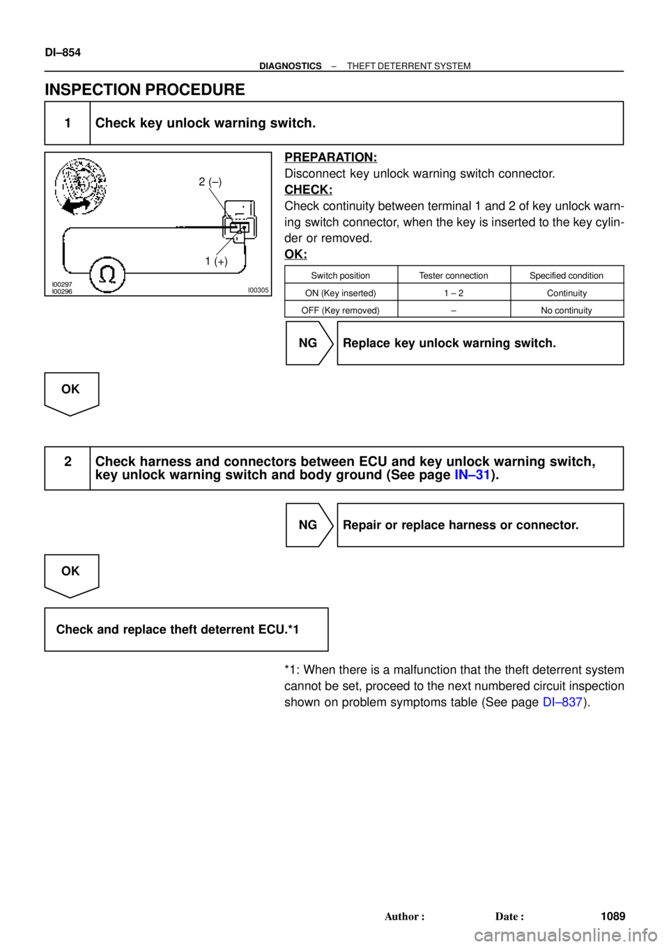
INSPECTION PROCEDURE
1 Check key unlock warning switch.
PREPARATION:
Disconnect key unlock warning switch connector.
CHECK:
Check continuity between terminal 1 and 2 of key unlock warn-
ing switch connector, when the key is inserted to the key cylin-
der or removed.
OK:
Switch positionTester connectionSpecified condition
ON (Key inserted)1 ± 2Continuity
OFF (Key removed)±No continuity
NG Replace key unlock warning switch.
OK
2 Check harness and connectors between ECU and key unlock warning switch,
key unlock warning switch and body ground (See page IN±31).
NG Repair or replace harness or connector.
OK
Check and replace theft deterrent ECU.*1
*1: When there is a malfunction that the theft deterrent system
cannot be set, proceed to the next numbered circuit inspection
shown on problem symptoms table (See page DI±837).
Page 3285 of 4770
± DIAGNOSTICSTHEFT DETERRENT SYSTEM
DI±865
1100 Author�: Date�:
INSPECTION PROCEDURE
1 Check operation of open door warning light.
CHECK:
Check that open door warning light comes ON when each door is opened, and goes OFF when all doors
are closed.
NG Check and repair open door warning light cir-
cuit.
OK
2 Check for open in harness and connector between theft deterrent ECU and door
courtesy switch (See page IN±31).
NG Repair or replace harness or connector.
OK
Check and replace theft deterrent ECU.*1
*1: When there is a malfunction that the theft deterrent system
cannot be set, proceed to the next numbered circuit inspection
shown on problem symptoms table (See page DI±837).
Page 3632 of 4770

BO0MB±01
N20950
Instrument Panel ReinforcementNN
DD
No.2 Instrumental Panel Bracket
No.1 Instrumental Panel Bracket
No.2 Instrumental Panel Brace
QQH N
N
N
N
GG
NG
NOB
NN
Instrument Panel Brace Mount
No.1 Instrument
Panel BraceFront Pillar Garnish
Front Pillar
GarnishFront
Passenger
Airbag
Assembly
20 (200, 14)
No.2 Side Defroster Nozzle
Cowl Side Trim
Front Door Openin
g
Cover
Instrument Panel
C
Remote Control
Mirror Hole Base
Upper Column
CoverHazard Warning
Switch
Lower Finish
PlateGlove Compartment
Door Finish PlateFront Door
Inside Scuff Plate
FFF
FJ
Glove
Compartment
No.2 Lower
Panel A
A
Cluster Finish
Panel
Lower Column
Cover
Front Door
Opening
Cover
Cowl Side
TrimD
DD
D
D
F
AA
Lower Panel
InsertCoin
BoxCombination SwitchCombination
MeterRadio Assembly
Center Cluster
Finish Panel
A/C
Control Assembly
35 (360, 26)
Steering
Wheel
Pad Steering Wheel No.1 Lower
Panel
Front Door
Inside Scuff PlateFront Console
Box
Center Console
Upper PanelF
F
B
B
Rear Console
Box
N´m (kgf´cm, ft´lbf) : Specified torque BO±72
± BODYINSTRUMENT PANEL
2430 Author�: Date�:
2001 CAMRY (RM819U)
INSTRUMENT PANEL
COMPONENTS
Page 3636 of 4770

8. REMOVE GLOVE COMPARTMENT ASSEMBLY
(a) Using a screwdriver, remove the glove compartmen")
N20988
N21023
7 Clips
N21024
6 Clips BO±76
± BODYINSTRUMENT PANEL
2434 Author�: Date�:
2001 CAMRY (RM819U)
8. REMOVE GLOVE COMPARTMENT ASSEMBLY
(a) Using a screwdriver, remove the glove compartment door
finish plate to the glove compartment box inside.
NOTICE:
When handling the airbag connector, be careful not to dam-
age the airbag wire harness.
HINT:
Tape the screwdriver tip before use.
(b) Pull up and disconnect the airbag connector.
(c) Remove the 4 screws, bolt and glove compartment as-
sembly.
9. REMOVE CENTER CONSOLE UPPER PANEL
Using a screwdriver, remove the panel, then disconnect the
connector.
HINT:
Tape the screwdriver tip before use.
10. REMOVE REAR CONSOLE BOX
Remove the 2 bolts, 2 screws and the console box.
11. REMOVE CENTER CLUSTER FINISH PANEL
Using a screwdriver, remove the panel, then disconnect the
connector.
HINT:
Tape the screwdriver tip before using.
12. REMOVE FRONT CONSOLE BOX
Remove the 2 screws and the front console box.
13. REMOVE RADIO ASSEMBLY
14. REMOVE A/C CONTROL ASSEMBLY
(See page AC±88 and AC±95)
15. REMOVE HAZARD WARNING SWITCH
16. REMOVE CLUSTER FINISH PANEL
(a) Remove the 2 screws.
(b) Using a screwdriver, remove the panel.
HINT:
Tape the screwdriver tip before use.
17. REMOVE COMBINATION METER
18. REMOVE REMOTE CONTROL MIRROR HOLE BASE