Page 3227 of 4770
DI05O±03
I00217
I00216
I00215
I00241
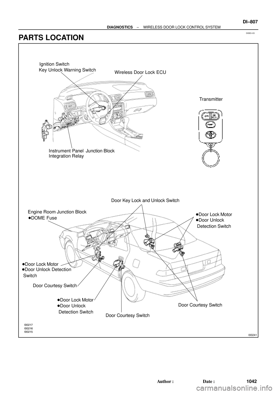
Ignition Switch
Key Unlock Warning Switch
Wireless Door Lock ECU
Transmitter
Instrument Panel Junction Block
Integration Relay
Engine Room Junction Block
�Door Lock Motor
�Door Unlock Detection
Switch
Door Courtesy Switch �DOME FuseDoor Key Lock and Unlock Switch
�Door Lock Motor
�Door Unlock
Detection Switch�Door Lock Motor
�Door Unlock
Detection Switch
Door Courtesy Switch
Door Courtesy Switch
± DIAGNOSTICSWIRELESS DOOR LOCK CONTROL SYSTEM
DI±807
1042 Author�: Date�:
PARTS LOCATION
Page 3228 of 4770
Wiring ColorConditionSTD Voltage")
DI1KR±03
I00227
1 2
63 74
8 5
9 10 11 12 13 14 15
DI±808
± DIAGNOSTICSWIRELESS DOOR LOCK CONTROL SYSTEM
1043 Author�: Date�:
TERMINALS OF ECU
Symbols (Terminals No.)Wiring ColorConditionSTD Voltage (V)
1 ± Ground (GND ± Ground )W ± BAlways.Below 1 V
4 G d(TAIL G d)GRTAIL lamps ºONºBelow 1 V4 ± Ground ( TAIL ± Ground )G ± RTAIL lamps ºOFFº10 ± 14 V
5 G d ( PINI G d )LGAlways.4 ± 6 V5 ± Ground ( PINI ± Ground )LGPush the PANIC switch.Below 1.5 V
7 G d(UL3 G d)RG
Door key lock and unlock switch ºUNLOCKº.
(Driver's Door)Below 1.5 V
7 ± Ground ( UL3 ± Ground )R ± GDoor key lock and unlock switch ºOFFº or ºLOCKº.
(Driver's Door)8 ± 10 V
8 ± 1 (+B ± E )RAlways.10 ± 14 V
9 ± Ground (PRG ± Ground )VIgnition switch ºONº10 ± 14 V
10 ± Ground (KSW ± Ground )L ± B
Key unlock warning switch ºONº.
(Key is inserted into key cylinder)Below 1 V10 Ground (KSW Ground )L B
Key unlock warning switch ºOFFº.10 ± 14 V
11 G d (LSWD G d)LR
Door unlock detection switch ºONº.
(Driver's Door)Below 1 V
11 ± Ground (LSWD ± Ground)L ± RDoor unlock detection switch ºOFFº.
(Driver's Door)10 ± 14 V
12 G d (LSWP G d)Y
Door unlock detection switch ºONº.
(Passenger's Door)Below 1 V
12 ± Ground (LSWP ± Ground)YDoor unlock detection switch ºOFFº.
(Passenger's Door)10 ± 14 V
13 G d(LSWR G d)LY
Door unlock detection switch ºONº.
(Either Rear Door)Below 1 V
13 ± Ground(LSWR ± Ground)L ± YDoor unlock detection switch ºOFFº.
(All Rear Doors)10 ± 14 V
14 G d (CTY G d )RWDoor courtesy switch ºONºBelow 1 V14 ± Ground (CTY ± Ground )R ± WDoor courtesy switch ºOFFº10 ± 14 V
15 G d (L G d )LWDoor key lock and unlock switch ºLOCKºBelow 1 V15 ± Ground (L ± Ground )L ± WDoor key lock and unlock switch ºOFFº or ºUNLOCKº8 ± 10 V
Page 3229 of 4770

DI05Q±03
± DIAGNOSTICSWIRELESS DOOR LOCK CONTROL SYSTEM
DI±809
1044 Author�: Date�:
PROBLEM SYMPTOMS TABLE
Perform troubleshooting of the circuit for the applicable problem symptom in the order given in the chart be-
low. Proceed to the page located for each circuit.
HINT:
�Troubleshooting of the wireless door lock control system is based on the premise that the door lock
control system and theft deterrent system are operating normally. Accordingly, before troubleshooting
the wireless door lock control system, first make certain that the door lock control system and theft de-
terrent system are operating normally.
�If the instruction ºProceed to next circuit inspection shown on matrix chartº is given in the flow chart
for each circuit, proceed to the circuit with the next highest number in the table to continue the check.
�If the trouble still reappears even through there are no abnormalities in any of the other circuits, check
and replace the Wireless Door Lock ECU as the last step.
SymptomSuspect AreaSee page
All functions of wireless door lock control system do no operate.
3. ECU Power Source Circuit.
4. Door Courtesy Switch Circuit.
5. Door Key Lock and Unlock Switch Circuit.
(Unlock Side)
6. Door Key Lock and Unlock Switch Circuit.
(Lock Side)
7. Key Unlock Warning Switch Circuit.
8. Wireless Door Lock ECU.DI±810
DI±821
DI±815
DI±817
DI±819
IN±31
Only door unlock operation is not possible (Lock operation is pos-
sible).
1. Door Key Lock and Unlock Switch Circuit
(Unlock Side)
2. Door Unlock Detection Switch Circuit
3. Wireless Door Lock ECU.DI±815
DI±819
IN±31
Only door lock operation is not possible (Unlock operation is pos-
sible).1. Door Key Lock and Unlock Switch Circuit
(Lock Side)
2. Wireless Door Lock ECUDI±817
IN±31
Only key confinement prevention function is not possible.1. Key Unlock Warning Switch Circuit
2. Wireless Door Lock ECUDI±819
IN±31
�Wireless door lock function operates even when each door is
opened.
�Automatic lock function operates even if any door is opened
within 30 seconds after all doors are unlocked by wireless door
lock control system.
1. Door Courtesy Switch Circuit
2. Wireless Door Lock ECUDI±821
IN±31
Wireless door lock functions incorrectly.
(Although one door is unlocked, when the transmitter switch is
pressed, all doors are unlocked.)1. Door Unlock Detection Switch Circuit
2. Wireless Door Lock ECUDI±813
IN±31
Warning operation will not be performed even if the panic button is
pressed.1. Panic Circuit
2. Wireless Door Lock ECUDI±823
IN±31
Page 3239 of 4770
I00224
Wireless Door Lock ECU
Key Unlock
Warning
SwitchKSW L±B
W±B
1M1J7 5 5
1
2
3 7
IG10
1D
J/C L±B
W±B1M
Integration Relay
Instrument Panel J/BW6 J10 Instrument Panel J/B
L±B B
J9B
J11
A
± DIAGNOSTICSWIRELESS DOOR LOCK CONTROL SYSTEM
DI±819
1054 Author�: Date�:
Key Unlock Warning Switch Circuit
CIRCUIT DESCRIPTION
When the key is inserted in the ignition key cylinder, the key unlock warning switch comes ON, and when
the key is not inserted the switch is OFF.
When the key unlock warning switch is ON, the ECU operates the key confinement prevention function.
WIRING DIAGRAM
DI05V±03
Page 3242 of 4770
N14695
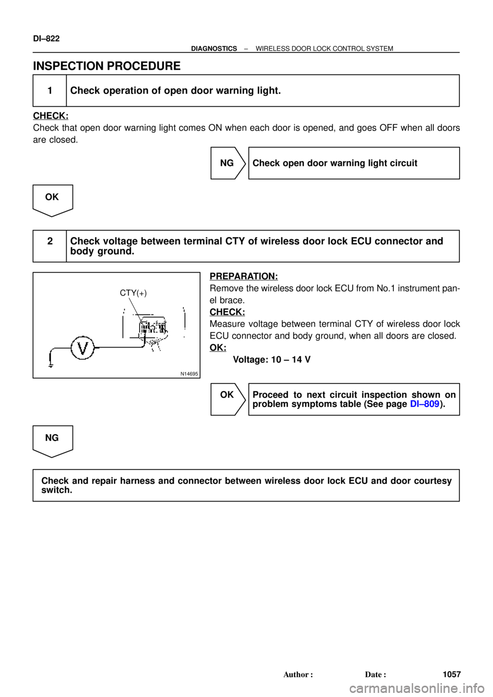
CTY(+)
DI±822
± DIAGNOSTICSWIRELESS DOOR LOCK CONTROL SYSTEM
1057 Author�: Date�:
INSPECTION PROCEDURE
1 Check operation of open door warning light.
CHECK:
Check that open door warning light comes ON when each door is opened, and goes OFF when all doors
are closed.
NG Check open door warning light circuit
OK
2 Check voltage between terminal CTY of wireless door lock ECU connector and
body ground.
PREPARATION:
Remove the wireless door lock ECU from No.1 instrument pan-
el brace.
CHECK:
Measure voltage between terminal CTY of wireless door lock
ECU connector and body ground, when all doors are closed.
OK:
Voltage: 10 ± 14 V
OK Proceed to next circuit inspection shown on
problem symptoms table (See page DI±809).
NG
Check and repair harness and connector between wireless door lock ECU and door courtesy
switch.
Page 3243 of 4770
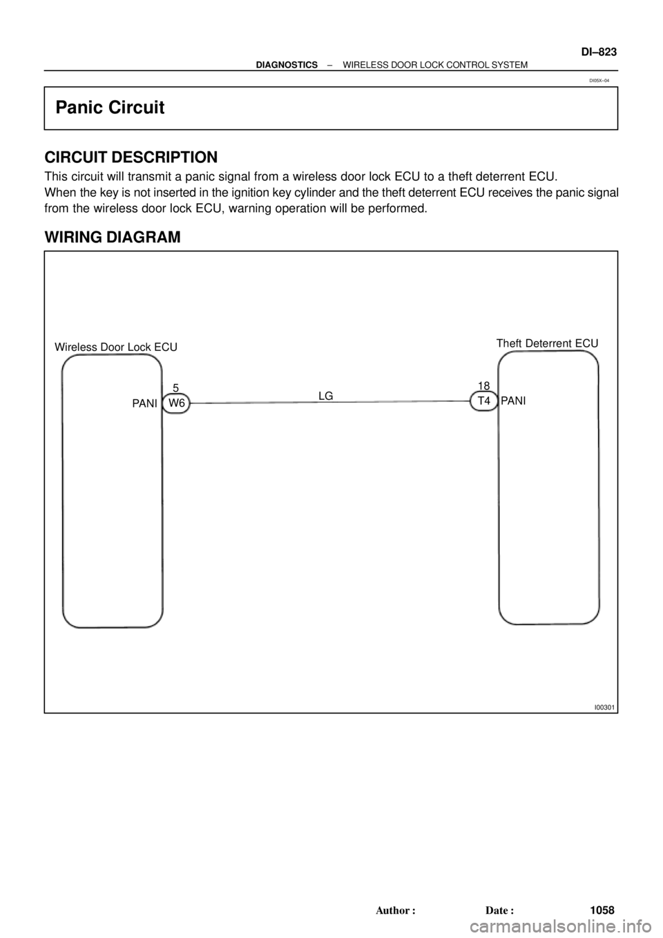
I00301
Wireless Door Lock ECUTheft Deterrent ECU
518
LG
PANI
PANIW6T4
± DIAGNOSTICSWIRELESS DOOR LOCK CONTROL SYSTEM
DI±823
1058 Author�: Date�:
Panic Circuit
CIRCUIT DESCRIPTION
This circuit will transmit a panic signal from a wireless door lock ECU to a theft deterrent ECU.
When the key is not inserted in the ignition key cylinder and the theft deterrent ECU receives the panic signal
from the wireless door lock ECU, warning operation will be performed.
WIRING DIAGRAM
DI05X±04
Page 3247 of 4770

DI06N±05
THEFT DETERRENT SYSTEM Check Sheet
Inspector 's name:
Customer 's Name
Date of VehicleRegistration No.
Registration Year
Frame No.
Odometer Reading / /km
Mile
Weather Conditions
When Problem
Occurred Frequency Problem OccursWeather
Outdoor temperature
/ /
� Constant � Sometimes ( Times per day, month)
� Once only Brought in
� Theft deterrent system cannot be set.
� Indicator light does not flash when the theft deterrent system is set.
(It stays on or does not light at all.)
� Theft deterrent system
does not operate.� When unlocked using the
door lock knob.
� When the engine hood is
opened.
� System cannot be
canceled once set.� When door is unlocked using key or wireless door lock control system.
� When the key is inserted in the ignition key cylinder and turned to ACC or ON
position.
(However, only when the system has never operated)
� When the luggage compartment door is opened with the key.
� System cannot be
canceled during warning
operation.� When door is unlocked using key or wireless door lock control system.
� When the key is inserted in the ignition key cylinder and turned to ACC or ON
position.
� Warning operation starts when the system is set and the door or luggage compartment door is opened with
the key.
� Others.
Date Problem First Occurred
� Fine � Cloudy � Rainy � Snowy
� Various/Others
� Hot � Warm � Cool
� Cold (Approx. 5F ( 5C))
Problem Symptom
Malfunction
� Horns only
� Theft deterrent horn only
� Headlights only
� Taillights only
� Starter cut only
� Door lock operation only
± DIAGNOSTICSTHEFT DETERRENT SYSTEM
DI±827
1062 Author�: Date�:
CUSTOMER PROBLEM ANALYSIS CHECK
Page 3253 of 4770
DI06P±05
I00233
I00234
I00236
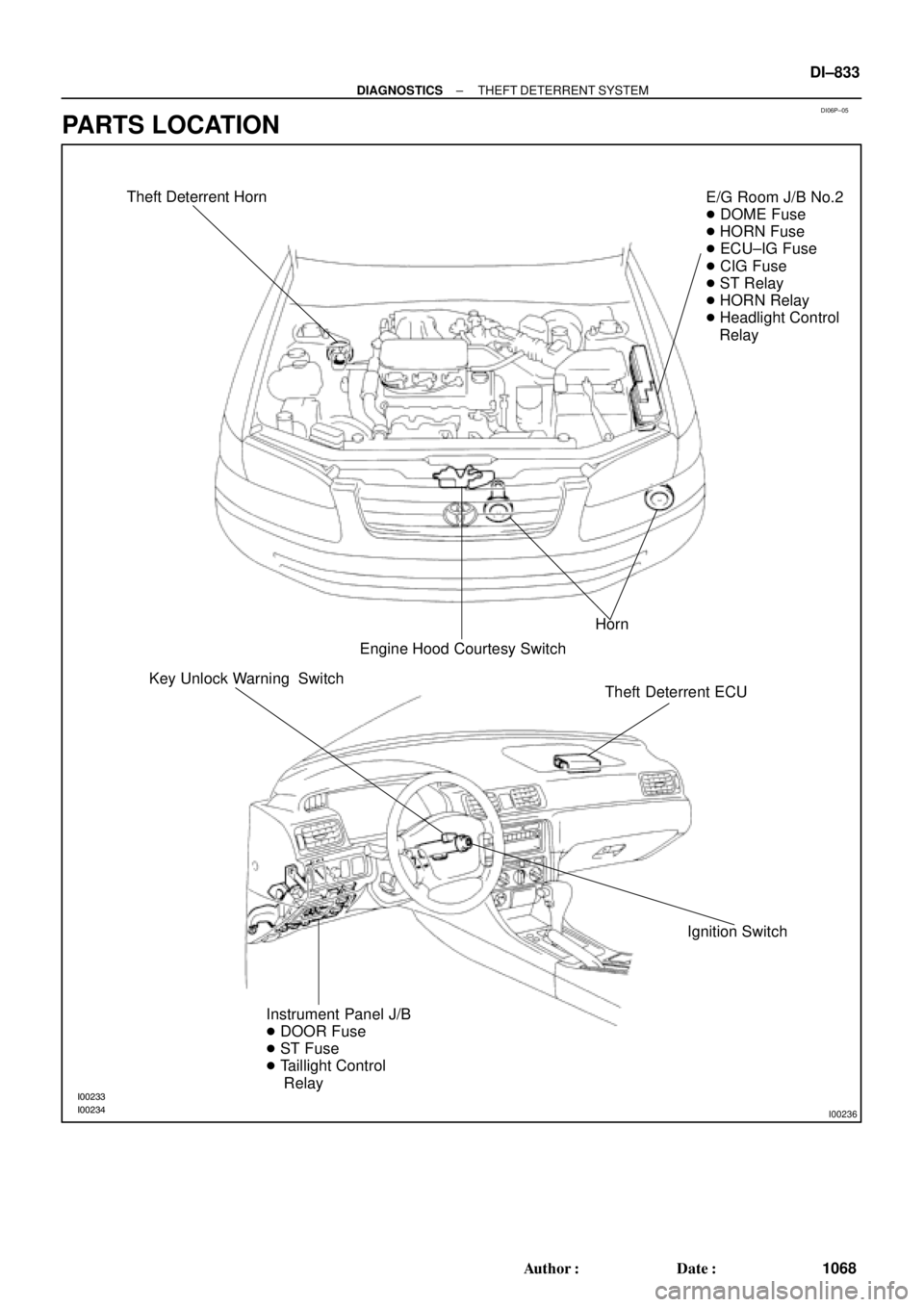
Theft Deterrent Horn
Horn
Engine Hood Courtesy SwitchE/G Room J/B No.2
� DOME Fuse
� HORN Fuse
� ECU±IG Fuse
� CIG Fuse
� ST Relay
� HORN Relay
� Headlight Control
Relay
Theft Deterrent ECU
Ignition Switch Key Unlock Warning Switch
Instrument Panel J/B
� DOOR Fuse
� ST Fuse
� Taillight Control
Relay
± DIAGNOSTICSTHEFT DETERRENT SYSTEM
DI±833
1068 Author�: Date�:
PARTS LOCATION