DI1JO±03
R05698
A15 A16A17
1 2 3 4 5 6 7 8 9 10
21 11 12 13
14
15 16 17 18 19
20 22 23 24 25 261 2 3 4 5
4 6 7
8
9 10 11 12 13 14 16 151
2 3 5 6
7 8
9 10 11 12
± DIAGNOSTICSABS & TRACTION CONTROL SYSTEM
DI±581
816 Author�: Date�:
TERMINALS OF ECU
Symbols (Terminals No.)Wiring ColorConditionSTD Voltage (V)
IG1 (A16 ± 8) ± GND (A15 ±
15, A17 ± 9, 10)B±R e W±BIG switch ON10 ± 14
R+ (A15 ± 1) ± SR (A15 ± 11)GR±R e GRIG switch ON, ABS warning light OFF9 ± 14
R+ (A15 ± 1) ± MR (A15 ± 24)GR±R e GR±LIG switch ONBelow 1.0
SFRR (A15 ± 26) ± GND (A15
± 15, A17 ± 9, 10)W±R e W±BIG switch ON, ABS warning light OFF10 ± 14
SFRH (A15 ± 13) ± GND (A15
± 15, A17 ± 9, 10)R±B e W±BIG switch ON, ABS warning light OFF10 ± 14
SFLR (A17 ± 1) ± GND (A15 ±
15, A17 ± 9, 10)W±L e W±BIG switch ON, ABS warning light OFF10 ± 14
SFLH (A17 ± 2) ± GND (A15 ±
15, A17 ± 9, 10)L±B e W±BIG switch ON, ABS warning light OFF10 ± 14
SRRR (A17 ± 7) ± GND (A15 ±
15, A17 ± 9, 10)R±G e W±BIG switch ON, ABS warning light OFF10 ± 14
SRRH (A17 ± 8) ± GND (A15 ±
15, A17 ± 9, 10)W±R e W±BIG switch ON, ABS warning light OFF10 ± 14
SRLR (A15 ± 12) ± GND (A15 ±
15, A17 ± 9, 10)LG±B e W±BIG switch ON, ABS warning light OFF10 ± 14
SRLH (A15 ± 25) ± GND (A15 ±
15, A17 ± 9, 10)G±Y e W±BIG switch ON, ABS warning light OFF10 ± 14
AST (A15 ± 10) ± GND (A15 ±
15, A17 ± 9, 10)R e W±BIG switch ON, ABS warning light OFF10 ± 14
WA (A16 ± 4) ± GND (A15 ± 15,GBWBIG switch ON, ABS warning light ONBelow 2.0WA (A16 4) GND (A15 15,
A17 ± 9, 10)G±B e W±BIG switch ON, ABS warning light OFF10 ± 14
STP (A16 ± 16) ± GND (A15 ±GWWBStop light switch OFFBelow 1.5STP (A16 16) GND (A15
15, A17 ± 9, 10)G±W e W±BStop light switch ON8 ± 14
D/G (A15 ± 22) ± GND (A15 ±
15, A17 ± 9, 10)R±L e W±BIG switch ON, ABS warning light ON10 ± 14
Tc (A15 ± 9) ± GND (A15 ± 15,
A17 ± 9, 10)LG±R e W±BIG switch ON8 ± 14
Ts (A15 ± 23) ± GND (A15 ± 15,
A17 ± 9, 10)R±Y eW±BIG switch ON8 ± 14
FR+ (A15 ± 17) ± FR± (A15 ±
18)W e BIG switch ON, slowly turn right front wheelAC generation
FL+ (A15 ± 5) ± FL± (A15 ± 4)R e GIG switch ON, slowly turn left front wheelAC generation
RR+ (A16 ± 9) ± RR± (A16 ±
10)W e BIG switch ON, slowly turn right rear wheelAC generation
RL+ (A16 ± 2) ± RL± (A16 ± 1)R e GIG switch ON, slowly turn left rear wheelAC generation
DI04I±04
± DIAGNOSTICSABS & TRACTION CONTROL SYSTEM
DI±583
818 Author�: Date�:
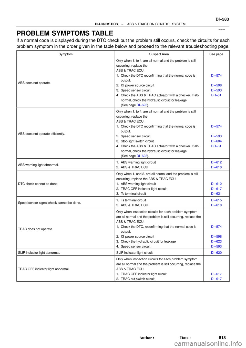
PROBLEM SYMPTOMS TABLE
If a normal code is displayed during the DTC check but the problem still occurs, check the circuits for each
problem symptom in the order given in the table below and proceed to the relevant troubleshooting page.
SymptomSuspect AreaSee page
ABS does not operate.
Only when 1. to 4. are all normal and the problem is still
occurring, replace the
ABS & TRAC ECU.
1. Check the DTC reconfirming that the normal code is
output.
2. IG power source circuit
3. Speed sensor circuit
4. Check the ABS & TRAC actuator with a checker. If ab-
normal, check the hydraulic circuit for leakage
(See page DI±623).
DI±574
DI±598
DI±593
BR±61
ABS does not operate efficiently.
Only when 1. to 4. are all normal and the problem is still
occurring, replace the
ABS & TRAC ECU.
1. Check the DTC reconfirming that the normal code is
output.
2. Speed sensor circuit.
3. Stop light switch circuit.
4. Check the ABS & TRAC actuator with a checker. If ab-
normal, check the hydraulic circuit for leakage
(See page DI±623).
DI±574
DI±593
DI±604
BR±61
ABS warning light abnormal.1. ABS warning light circuit
2. ABS & TRAC ECUDI±612
DI±610
DTC check cannot be done.
Only when 1. and 2. are all normal and the problem is still
occurring, replace the ABS & TRAC ECU.
1. ABS warning light circuit
2. TRAC OFF indicator light circuit
3. Tc terminal circuit
DI±612
DI±617
DI±621
Speed sensor signal check cannot be done.1. Ts terminal circuit
2. ABS & TRAC ECUDI±615
DI±610
TRAC does not operate.
Only when inspection circuits for each problem symptom
are all normal and the problem is still occurring, replace the
ABS & TRAC ECU.
1. Check the DTC, reconfirming that the normal code is
output.
2. IG power source circuit
3. Check the hydraulic circuit for leakage
4. Speed sensor circuit
DI±574
DI±598
DI±623
DI±593
SLIP indicator light abnormal.SLIP indicator light circuitDI±620
TRAC OFF indicator light abnormal.
Only when inspection circuits for each problem symptom
are all normal and the problem is still occurring, replace the
ABS & TRAC ECU.
1. TRAC OFF indicator light circuit
2. TRAC cut switch circuit
DI±617
DI±617
± DIAGNOSTICSABS & TRACTION CONTROL SYSTEM
DI±611
846 Author�: Date�:
4 Check battery positive voltage.
CHECK:
Check the battery positive voltage.
OK:
10 ± 14 V
NG Check and repair the charging system
5S±FE engine: (See page CH±1)
1MZ±FE engine: (See page CH±1).
OK
5 Check ABS warning light.
PREPARATION:
(a) Disconnect the connector from the ABS & TRAC ECU.
(b) Turn the ignition switch ON.
CHECK:
Check the ABS warning light goes off.
OK Check and replace ABS & TRAC ECU.
NG
Check for short circuit in harness and connector between ABS warning light, DLC1, DLC2, and
ABS & TRAC ECU (See page IN±31)
F00168
BatteryABS & TRAC
Solenoid Relay Engine Room R/B No. 3
3ABS & TRAC
ECU
A8 1
R±L
C 5 4
IG3 IK2 6
J/C C10
EA4ABS Warning Light 8
12 II3
G±B23 2
22 ABS & TRAC
Actuator
DLC1 Short
Pin
WA
J29 33 3 3
3
W±B4
ABS & TRAC
ECUR±L
4
R±L
II3 5
G±B
C C G±B R±LC107
ABS & TRAC ECU R±LR±L
J/C
D 1D
GAUGE Instrument Panel J/B
A16 J4 D
G±B4 W±L
2
DI±612
± DIAGNOSTICSABS & TRACTION CONTROL SYSTEM
847 Author�: Date�:
ABS Warning Light Circuit
CIRCUIT DESCRIPTION
If the ECU detects a trouble, it lights the ABS warning light while at the same time prohibiting ABS control.
At this time, the ECU records a DTC in memory.
Connect terminals Tc and E
1 of the DLC1 or DLC2 to make the ABS warning light blink and output the DTC.
WIRING DIAGRAM
INSPECTION PROCEDURE
Troubleshoot in accordance with the chart below for each trouble symptom.
ABS warning light does not light upGo to step 1
ABS warning light remains onGo to step 3
1 Check ABS warning light.
See combination meter troubleshooting on page BE±2.
NG Repair bulb or combination meter assembly.
OK
DI04V±04