Page 4646 of 4770
WARRANTY PARTS MARKING PROCEDURE ± PG006-03September 26, 2003
Page 3 of 3
NOTE:
The following parts do not have to be marked unless the technician can determine
failure and location.
air induction/ejection systems fuel injection systems
all computers fuel injectors
alternators fuel pump
audio (internal) ignition system
batteries internal engine components
bearings internal transmission components
belts oil cooler
catalytic converter power door lock switches
crankshaft remanufactured parts
cruise control starters
distributors suspension components
EGR systems valve covers
engine control systems window regulators
exchange parts wiper motors
exhaust systems
Parts
Marking
List
(Continued)
Page 4706 of 4770
TRANSMISSION OIL COOLER INSTALLATION ± TC003±97 October 17, 1997
Procedure1. Parts removal in preparation for cooler
installation:
A. Remove the 9 bolts, 2 screws and
the center engine under cover.
B. Remove the engine coolant
temperature switch connector and
the wire clamp.
C. Remove battery and tray.
D. Disconnect the cooling fan
connector.
E. Disconnect the No.1 engine coolant
temperature switch wire connector.
F. Remove the 2 bolts and then the
cooling fan.
Page 2 of 6
Fig. 2Center Engine Under Cover
Fig. 3ClampSwitch
Fig. 4
Page 4710 of 4770

TRANSMISSION OIL COOLER INSTALLATION ± TC003±97 October 17, 1997
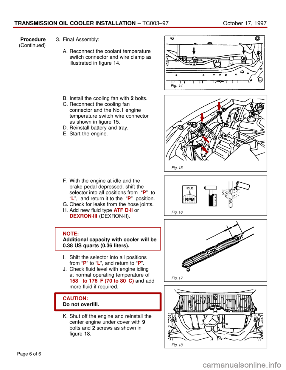
Procedure3. Final Assembly:
(Continued)
A. Reconnect the coolant temperature
switch connector and wire clamp as
illustrated in figure 14.
B. Install the cooling fan with 2 bolts.
C. Reconnect the cooling fan
connector and the No.1 engine
temperature switch wire connector
as shown in figure 15.
D. Reinstall battery and tray.
E. Start the engine.
F. With the engine at idle and the
brake pedal depressed, shift the
selector into all positions from ªPº to
ªLº, and return it to the ªPº position.
G. Check for leaks from the hose joints.
H. Add new fluid type ATF D´II or
DEXRON´III (DEXRON´II).
NOTE:
Additional capacity with cooler will be
0.38 US quarts (0.36 liters).
I. Shift the selector into all positions
from ªPº to ªLº, and return to ªPº.
J. Check fluid level with engine idling
at normal operating temperature of
158� to 176�F (70 to 80�C) and add
more fluid if required.
CAUTION:
Do not overfill.
K. Shut off the engine and reinstall the
center engine under cover with 9
bolts and 2 screws as shown in
figure 18.
Page 6 of 6
Fig. 15
Fig. 16
Fig. 17
Fig. 18
Page 4719 of 4770

O2S TEST RESULTS (MODE 05) ± SS002-03December 17, 2003
Page 2 of 43
1. Clear any stored Diagnostic Trouble Codes (DTCs) using the Toyota
Diagnostic Tester.
2. Start the engine.
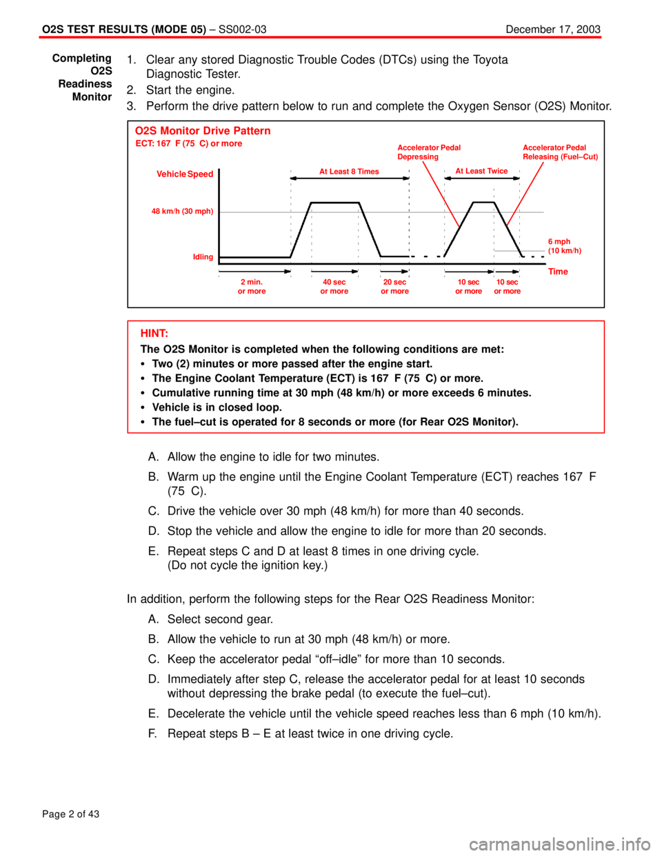
3. Perform the drive pattern below to run and complete the Oxygen Sensor (O2S) Monitor.
O2S Monitor Drive Pattern
ECT: 167�F (75�C) or more
Vehicle Speed
At Least 8 Times
48 km/h (30 mph)
IdlingAt Least Twice Accelerator Pedal
DepressingAccelerator Pedal
Releasing (Fuel±Cut)
6 mph
(10 km/h)
Time2 min.
or more40 sec
or more20 sec
or more10 sec
or more10 sec
or more
HINT:
The O2S Monitor is completed when the following conditions are met:
�Two (2) minutes or more passed after the engine start.
�The Engine Coolant Temperature (ECT) is 167�F (75�C) or more.
�Cumulative running time at 30 mph (48 km/h) or more exceeds 6 minutes.
�Vehicle is in closed loop.
�The fuel±cut is operated for 8 seconds or more (for Rear O2S Monitor).
A. Allow the engine to idle for two minutes.
B. Warm up the engine until the Engine Coolant Temperature (ECT) reaches 167�F
(75�C).
C. Drive the vehicle over 30 mph (48 km/h) for more than 40 seconds.
D. Stop the vehicle and allow the engine to idle for more than 20 seconds.
E. Repeat steps C and D at least 8 times in one driving cycle.
(Do not cycle the ignition key.)
In addition, perform the following steps for the Rear O2S Readiness Monitor:
A. Select second gear.
B. Allow the vehicle to run at 30 mph (48 km/h) or more.
C. Keep the accelerator pedal ªoff±idleº for more than 10 seconds.
D. Immediately after step C, release the accelerator pedal for at least 10 seconds
without depressing the brake pedal (to execute the fuel±cut).
E. Decelerate the vehicle until the vehicle speed reaches less than 6 mph (10 km/h).
F. Repeat steps B ± E at least twice in one driving cycle.
Completing
O2S
Readiness
Monitor
Page 4721 of 4770

NOTE:
Before the O2S Monitor completes or after the ignition switch is turned OFF, the
Diagnostic Tester displays the viewable upper limit or a lower limit of the test value
(example: 0 V, 1.275 V, 0 s [seconds], 10.2 s, 0 and 255).
O2S TEST RESULTS (MODE 05) ± SS002-03December 17, 2003
Page 4 of 43
1. Determine the correct O2S Failure Threshold Chart for your vehicle by looking in the
ªO2S Application Table,º pages 5 ± 9 in this bulletin.
2. Select appropriate year, model, and engine for specified O2S Failure
Threshold Chart.
3. Compare O2S test results with the specified O2S Failure Threshold Chart. It may be
necessary to convert O2S test results to a specific measurement unit using the
conversion factor that is supplied in the specified table. See example below:
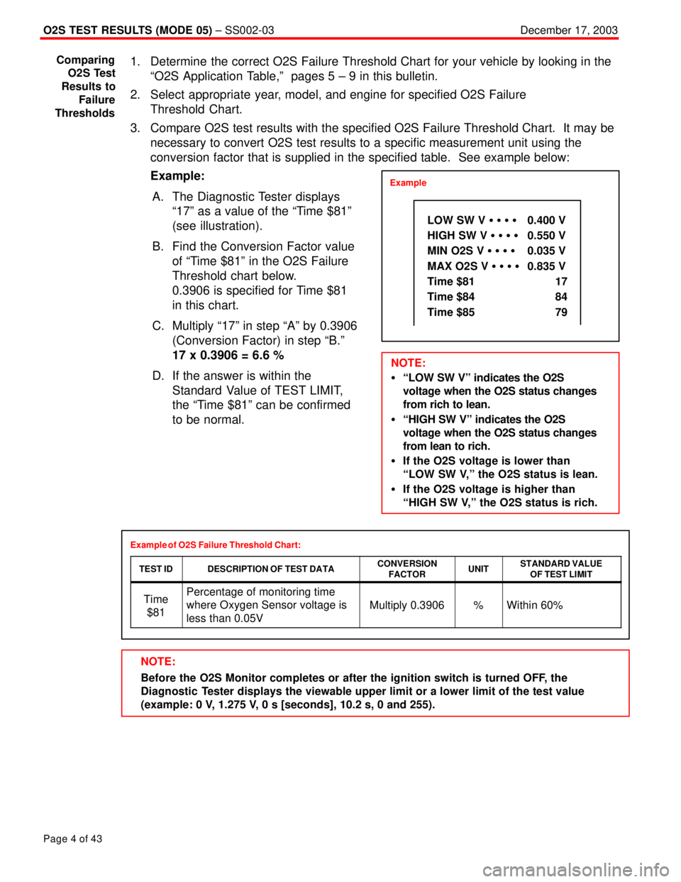
Example:
A. The Diagnostic Tester displays
ª17º as a value of the ªTime $81º
(see illustration).
B. Find the Conversion Factor value
of ªTime $81º in the O2S Failure
Threshold chart below.
0.3906 is specified for Time $81
in this chart.
C. Multiply ª17º in step ªAº by 0.3906
(Conversion Factor) in step ªB.º
17 x 0.3906 = 6.6 %
D. If the answer is within the
Standard Value of TEST LIMIT,
the ªTime $81º can be confirmed
to be normal.
Example of O2S Failure Threshold Chart:
TEST ID
DESCRIPTION OF TEST DATACONVERSION
FACTORUNITSTANDARD VALUE
OF TEST LIMIT
Time
$81Percentage of monitoring time
where Oxygen Sensor voltage is
less than 0.05V
Multiply 0.3906%Within 60%
Comparing
O2S Test
Results to
Failure
Thresholds
Example
LOW SW V � � � � 0.400 V
HIGH SW V � � � � 0.550 V
MIN O2S V � � � �0.035 V
MAX O2S V � � � �0.835 V
Time $81 17
Time $84 84
Time $85 79
NOTE:
�ªLOW SW Vº indicates the O2S
voltage when the O2S status changes
from rich to lean.
�ªHIGH SW Vº indicates the O2S
voltage when the O2S status changes
from lean to rich.
�If the O2S voltage is lower than
ªLOW SW V,º the O2S status is lean.
�If the O2S voltage is higher than
ªHIGH SW V,º the O2S status is rich.
Page 4722 of 4770

O2S TEST RESULTS (MODE 05) ± SS002-03December 17, 2003
Page 5 of 43
MODEL YEARMODELENGINEDRIVE TRAINCERTIFICATION
SEE CHART NO.
(TSB PAGE)
Avalon1MZ±FEAll50±State1 (p. 10)
5S FEAllCalifornia2 (p. 11)
Camry5S±FEAllFederal1(p10)y
1MZ±FEAll50±State1 (p. 10)
7A±FEAll50±State1 (p. 10)
Celica5S FEAllCalifornia2 (p. 11)5S±FEAllFederal1 (p. 10)
CorollaALLAll50±State1 (p. 10)
1996Land Cruiser1FZ±FEAll50±State1 (p. 10)
Paseo5E±FEAll50±State1 (p. 10)
Previa2TZ±FZEAll50±State1 (p. 10)
RAV43S±FEAll50±State2 (p. 11)
SupraALLAll50±State1 (p. 10)
TacomaALLAll50±State1 (p. 10)
Tercel5E±FEAll50±State1 (p. 10)
T100ALLAll50±State1 (p. 10)
4RunnerALLAll50±State1 (p. 10)
Avalon1MZ±FEAll50±State1 (p. 10)
5S FEAllCalifornia3 (p. 12)
Camry5S±FEAllFederal1(p10)y
1MZ±FEAll50±State1 (p. 10)
7A±FEAll50±State1 (p. 10)
Celica5S FEAllCalifornia2 (p. 11)5S±FEAllFederal1 (p. 10)
CorollaALLAll50±State1 (p. 10)
Land Cruiser1FZ±FEAll50±State1 (p. 10)
Paseo5E±FEAll50±State1 (p. 10)
Previa2TZ±FZEAll50±State1 (p. 10)
1997RAV43S±FEAll50±State2 (p. 11)
SupraALLAll50±State1 (p. 10)
2RZ±FEAll50±State
A/T50±State1 (p. 10)
Tacoma3RZ±FEM/T, 2WD50±State
()
M/T, 4WD50±State2(p11)5VZ±FEAll50±State2 (p. 11)
Tercel5E±FEAll50±State1 (p. 10)
T1003RZ±FEAll50±State1 (p. 10)T1005VZ±FEAll50±State2 (p. 11)
4Runner3RZ±FEAll50±State1 (p. 10)4Runner5VZ±FEAll50±State2 (p. 11)
O2S
Application
Table
Page 4723 of 4770

O2S TEST RESULTS (MODE 05) ± SS002-03December 17, 2003
Page 6 of 43
MODEL YEARMODELENGINEDRIVE TRAINCERTIFICATION
SEE CHART NO.
(TSB PAGE)
Avalon1MZ FEAllCalifornia4 (p. 12)Avalon1MZ±FEAllFederal1 (p. 10)
5S FEAllCalifornia3 (p. 12)5S±FEAllFederal2 (p. 11)
CamryA/TCalifornia4 (p. 12)y
1MZ±FEA/TFederal1(p10)M/T50±State1 (p. 10)
Celica5S FEAllCalifornia2 (p. 11)Celica5S±FEAllFederal1 (p. 10)
Corolla1ZZ±FEAll50±State2 (p. 11)
1998Land Cruiser2UZ±FEAll50±State2 (p. 11)
Paseo5E±FEAll50±State1 (p. 10)
RAV43S FEAllCalifornia3 (p. 12)RAV43S±FEAllFederal2 (p. 11)
Sienna1MZ±FEAll50±State1 (p. 10)
Supra2JZ±GEAll50±State2 (p. 11)Supra2JZ±GTEAll50±State1 (p. 10)
TacomaALLAll50±State2 (p. 11)
Tercel5E±FEAll50±State1 (p. 10)
T100ALLAll50±State2 (p. 11)
4RunnerALLAll50±State2 (p. 11)
Avalon1MZ FEAllCalifornia4 (p. 12)Avalon1MZ±FEAllFederal5 (p. 13)
Camry CNG5S±FNEAll50±State6 (p. 13)
Celica5S±FEAll50±State5 (p. 13)
Corolla1ZZ±FEAll50±State2 (p. 11)
Land Cruiser2UZ±FEAll50±State2 (p. 11)
Paseo5E±FEAll50±State1 (p. 10)
RAV43S FEAllCalifornia3 (p. 12)RAV43S±FEAllFederal2 (p. 11)
Sienna1MZ FEAllCalifornia4 (p. 12)
1999Sienna1MZ±FEAllFederal5 (p. 13)
5S FEAllCalifornia3 (p. 12)5S±FEAllFederal5 (p. 13)
SolaraA/TCalifornia4 (p. 12)
1MZ±FEA/TFederal5(p13)M/T50±State5 (p. 13)
TacomaALLAll50±State2 (p. 11)
Tercel5E±FEAll50±State1 (p. 10)
3RZ±FEAll50±State2 (p. 11)
4Runner5VZ FEAllCalifornia4 (p. 12)5VZ±FEAllFederal2 (p. 11)
O2S
Application
Table
(Continued)
Page 4724 of 4770

O2S TEST RESULTS (MODE 05) ± SS002-03December 17, 2003
Page 7 of 43
MODEL YEARMODELENGINEDRIVE TRAINCERTIFICATION
SEE CHART NO.
(TSB PAGE)
Avalon1MZ±FEAll50±State4 (p. 12)
Camry CNG5S±FNEAll50±State6 (p. 13)
CelicaALLAll50±State1 (p. 10)
Corolla1ZZ±FEAll50±State7 (p. 14)
ECHO1NZ±FEAll50±State1 (p. 10)
Land Cruiser2UZ±FEAll50±State2 (p. 11)
MR21ZZ±FEAll50±State1 (p. 10)
RAV43S FEAllCalifornia4 (p. 12)RAV43S±FEAllFederal2 (p. 11)
Sienna1MZ FEAllCalifornia4 (p. 12)Sienna1MZ±FEAllFederal5 (p. 13)
5S FEAllCalifornia4 (p. 12)5S±FEAllFederal5 (p. 13)
SolaraA/TCalifornia4 (p. 12)
20001MZ±FEA/TFederal5(p13)M/T50±State5 (p. 13)
2RZ FEAllCalifornia4 (p. 12)2RZ±FEAllFederal2 (p. 11)
Tacoma3RZ FEAllCalifornia4 (p. 12)Tacoma3RZ±FEAllFederal2 (p. 11)
5VZ FEAllCalifornia8 (p. 15)5VZ±FEAllFederal2 (p. 11)
2UZ±FEAll50±State2 (p. 11)
Tundra5VZ FEAllCalifornia8 (p. 15)5VZ±FEAllFederal2 (p. 11)
3RZ FEAllCalifornia4 (p. 12)
4Runner
3RZ±FEAllFederal2 (p. 11)4Runner
5VZ FEAllCalifornia8 (p. 15)5VZ±FEAllFederal2 (p. 11)
O2S
Application
Table
(Continued)