Page 2347 of 4770
CL03M±02
Q10089
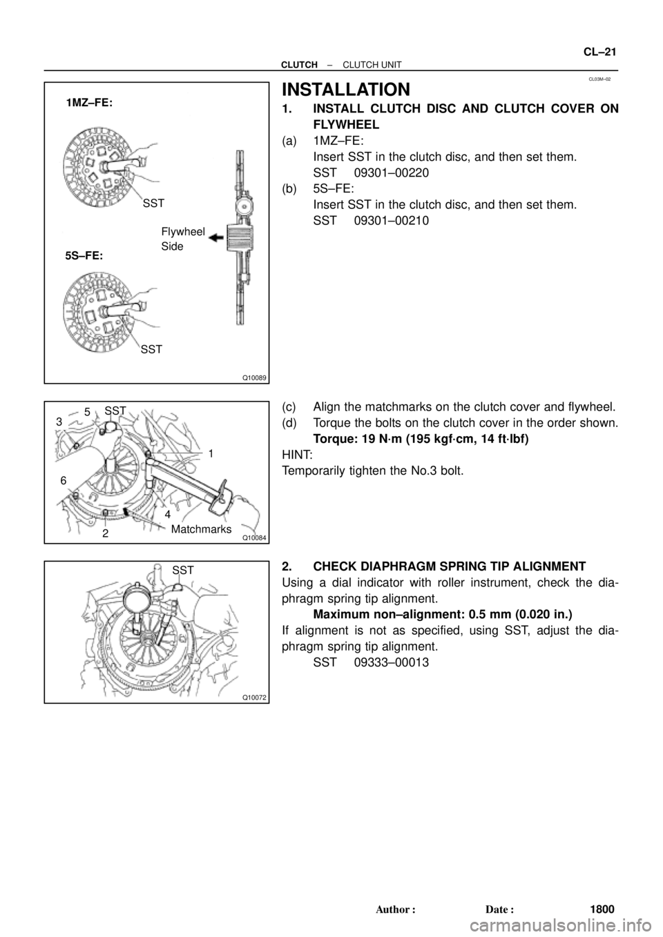
1MZ±FE:
5S±FE:SST
Flywheel
Side
SST
Q10084
SST
1
Matchmarks
4
2
6
35
Q10072
SST
± CLUTCHCLUTCH UNIT
CL±21
1800 Author�: Date�:
INSTALLATION
1. INSTALL CLUTCH DISC AND CLUTCH COVER ON
FLYWHEEL
(a) 1MZ±FE:
Insert SST in the clutch disc, and then set them.
SST 09301±00220
(b) 5S±FE:
Insert SST in the clutch disc, and then set them.
SST 09301±00210
(c) Align the matchmarks on the clutch cover and flywheel.
(d) Torque the bolts on the clutch cover in the order shown.
Torque: 19 N´m (195 kgf´cm, 14 ft´lbf)
HINT:
Temporarily tighten the No.3 bolt.
2. CHECK DIAPHRAGM SPRING TIP ALIGNMENT
Using a dial indicator with roller instrument, check the dia-
phragm spring tip alignment.
Maximum non±alignment: 0.5 mm (0.020 in.)
If alignment is not as specified, using SST, adjust the dia-
phragm spring tip alignment.
SST 09333±00013
Page 3767 of 4770
MX04E±01
MX±8
± MANUAL TRANSAXLE (S51)MANUAL TRANSAXLE UNIT
1858 Author�: Date�:
INSTALLATION
Installation is in the reverse order of removal (See page MX±4).
HINT:
�Front wheel alignment (See page SA±4).
�Do the road test.
Page 3811 of 4770
MX051±01
± MANUAL TRANSAXLE (E153)MANUAL TRANSAXLE UNIT
MX±9
1810 Author�: Date�:
INSTALLATION
Installation is in the reverse order of removal (See page MX±4).
HINT:
After installation, check and inspect items as follows.
�Front wheel alignment (See page SA±4).
�Do the road test.
Page 4005 of 4770
SS09Q±01
± SERVICE SPECIFICATIONSCLUTCH
SS±43
206 Author�: Date�:
CLUTCH
SERVICE DATA
Pedal height from asphalt sheet 1MZ±FE161.8 ± 171.8 mm (6.370 ± 6.764 in.)
Pedal height from asphalt sheet 5S±FE156.8 ± 166.8 mm (6.173 ± 6.567 in.)
Push rod play at pedal top1.0 ± 5.0 mm (0.039 ± 0.197 in.)
Pedal freeplay5.0 ± 15.0 mm (0.197 ± 0.591 in.)
Clutch start switch ON±OFF Stroke5.0 ± 0.5 mm (0.197 ± 0.020 in.)
Clutch release point from pedal full stroke end position25 mm (0.98 in.) or more
Disc rivet head depth Min.0.3 mm (0.012 in.)
Disc runout Max.0.8 mm (0.031 in.)
Flywheel runoutMax.0.1 mm (0.004 in.)
Diaphragm spring finger wear Max. depth0.6 mm (0.024 in.)
Diaphragm spring finger wear Max. width5.0 mm (0.197 in.)
Diaphragm spring tip non±alignmentMax.0.5 mm (0.020 in.)
Page 4021 of 4770

Cold tire inflationP195/70R1")
SS04W±01
± SERVICE SPECIFICATIONSSUSPENSION AND AXLE
SS±59
222 Author�: Date�:
SUSPENSION AND AXLE
SERVICE DATA
P195/70R14 90SFront, Rear*1210 kPa (2.1 kgf/cm2, 30 psi)
Cold tire inflationP195/70R14 90SFront, Rear*2210 kPa (2.1 kgf/cm2, 30 psi)pressure
(Normal driving)P205/65R15 92HFront, Rear*1220 kPa (2.2 kgf/cm2, 32 psi)(Normal driving)P205/65R15 92HFront, Rear*2200 kPa (2.0 kgf/cm2, 29 psi)
P195/70R14 90SFront, Rear*3210 kPa (2.1 kgf/cm2, 30 psi)
Cold tire inflationP195/70R14 90SFront, Rear*4240 kPa (2.4 kgf/cm2, 35 psi)pressure
(Trailer towing)P205/65R15 92HFront, Rear*3220 kPa (2.2 kgf/cm2, 32 psi)(Trailer towing)P205/65R15 92HFront, Rear*4240 kPa (2.4 kgf/cm2, 35 psi)
V hi l h i ht 195/70R14Front*5212 mm (8.35 in.)Vehicle height195/70R14Rear*6264 mm (10.39 in.)
205/65R15Front*5215 mm (8.46 in.)205/65R15Rear*6266 mm (10.49 in.)
Camber 5S±FE±0°36'±45'(0.6°±0.75°)Camber 5S ± FE
1MZ ± FE
±036 ± 45 (0.6 ± 0.75)
±0°37' ± 45' (0.62° ± 0.75°)1MZ ± FE±037 ± 45 (0.62 ± 0.75)
Left ± right error45' (0.75°) or less
Front wheel
alignment
Caster 5S ± FE
1MZ ± FE
Left ± right error2°10' ± 45' (2.17° ± 0.75°)
2°11' ± 45' (2.18° ± 0.75°)
45' (0.75°) or less
alignmentSteering axis inclination 5S ± FE
1MZ ± FE
Left ± right error13°01' ± 45' (13.02° ± 0.75°)
13°04' ± 45' (13.07° ± 0.75°)
45' (0.75°) or less
Toe±in (Total)
Rack end length difference0° ± 12' (0° ± 0.2°)
0 ± 2 mm (0 ± 0.08 in.)
1.5 mm (0.059 in.) or less
Wh l l 195/70R14Inside wheel 37°12' ± 2° (37.2° ± 2°)Wheel angle195/70R14Outside wheel 32°21' (32.45°)
205/65R15Inside wheel 35°47' ± 2° (35.78° ± 2°)205/65R15Outside wheel 31°25' (31.42°)
Rear wheel
li t
Camber 5S ± FE
1MZ ± FE
Left ± right error±0°42' ± 45' (±0.7° ± 0.75°)
±0°45' ± 45' (±0.75° ± 0.75°)
45' (0.75°) or less
alignmentToe±in (Total)
No.2 lower suspension arm length difference0°24' ± 12' (0.4° ± 0.2°)
4 ± 2 mm (0.16 ± 0.08 in.)
1 mm (0.04 in.) or less
*1: For all loads including rated loads
*2: For reduced loads (1 to 4 passengers)
*3: For driving under 160 km/h (100 mph)
*4: For driving at 160 km/h (100 mph) or over
*5: Front measuring point
Measure from the ground to the center of the front side lower suspension arm mounting bolt.
*6: Rear measuring point
Measure from the ground to the center of the strut rod mounting bolt.
Page 4292 of 4770

SR06C±01
SR±2
± STEERINGTROUBLESHOOTING
2097 Author�: Date�:
TROUBLESHOOTING
PROBLEM SYMPTOMS TABLE
Use the table below to help you find the cause of the problem. The numbers indicate the priority of the likely
cause of the problem. Check each part in the order shown. If necessary, repair or replace these parts.
SymptomSuspect AreaSee page
Hard steering
1. Tires (Improperly inflated)
2. Power steering fluid level (Low)
3. Drive belt (Loose)
4. Front wheel alignment (Incorrect)
5. Steering system joints (Worn)
6. Suspension arm ball joints (Worn)
7. Steering column (Binding)
8. Power steering vane pump
9. Power steering gearSA±2
SR±5
SR±3
SA±4
±
SA±45
±
SR±18
SR±31
Poor return
1. Tires (Improperly inflated)
2. Front wheel alignment (Incorrect)
3. Steering column (Binding)
4. Power steering gearSA±2
SA±4
±
SR±31
Excessive play
1. Steering system joints (Worn)
2. Suspension arm ball joints (Worn)
3. Intermediate shaft, Sliding yoke (Worn)
4. Front wheel bearing (Worn)
5. Power steering gear±
SA±45
±
SA±10
SR±31
Abnormal noise
1. Power steering fluid level (Low)
2. Steering system joints (Worn)
3. Power steering vane pump
4. Power steering gearSR±5
±
SR±18
SR±31
Page 4340 of 4770
SR±50
± STEERINGPOWER STEERING GEAR
2145 Author�: Date�:
13. TORQUE STEERING WHEEL SET NUT
Torque: 35 N´m (360 kgf´cm, 26 ft´lbf)
14. INSTALL STEERING WHEEL PAD
(See page SR±16)
15. CHECK FRONT WHEEL ALIGNMENT
(See page SA±4)
Page 4341 of 4770

SA077±01
± SUSPENSION AND AXLETROUBLESHOOTING
SA±1
1952 Author�: Date�:
TROUBLESHOOTING
PROBLEM SYMPTOMS TABLE
Use the table below to help you find the cause of the problem. The numbers indicate the priority of the likely
cause of the problem. Check each part in order. If necessary, replace these parts.
SymptomSuspect AreaSee page
Wander/pulls
1. Tire (Worn or improperly inflated)
2. Wheel alignment (Incorrect)
3. Steering linkage (Loosen or worn)
4. Hub bearings (Worn)
5. Suspension parts (Worn)
6. Steering gear (Out of adjustment or broken)SA±2
SA±4
SA±7
±
SA±10
±
±
Bottoming
1. Vehicle (Overloaded)
2. Spring (Weak)
3. Shock absorber (Worn)±
SA±33
SA±56
SA±33
SA±56
Sways/pitches
1. Tire (Worn or improperly inflated)
2. Stabilizer bar (Bent or broken)
3. Shock absorber (Worn)SA±2
SA±47
SA±69
SA±33
SA±56
Front wheel shimmy
1. Tire (Worn or improperly inflated)
2. Wheels (Out of balance)
3. Shock absorber (Worn)
4. Wheel alignment (Incorrect)
5. Ball joints (Worn)
6. Hub bearings (Worn)
7. Steering linkage (Loosen or worn)
8. Steering gear (Out of adjustment or broken)SA±2
SA±2
SA±33
SA±56
SA±4
SA±7
SA±43
SA±10
±
±
Abnormal tire wear
1. Tire (Worn or improperly inflated)
2. Wheels (Out of balance)
3. Suspension parts (Worn)
4. Shock absorber (Worn)SA±2
SA±2
±
SA±33
SA±56